Note: Descriptions are shown in the official language in which they were submitted.
21~13~~_~
WATER TREATMENT SYSTEM
BACKGROUND OF THE INVENTION
1. Field of the Invention
This invention relates to treatment systems
that treat municipal and industrial wastewater, raw water
for a potable water supply, stormwater, urban runoff and
combined sewer overflow (CSO), or any other flows of water
having suspended particles. The inventive systems remove
suspended particles from the water and, in particular
applications for handling stormwater and CSO, retain and
balance the flow to be treated. The inventive systems
also use gas bubbles to dislodge particles trapped between
inclined plates.
2. Description of Related Art
Tanks for treating water to remove particles often
utilize multiple parallel inclined plates with gaps
between the plates that form passageways for the water to
flow between the plates. The inclination of the plates
creates a larger total horizontal projected settling area
than a tank without inclined plates. This enlarged
settling area increases particle settling ability in
accordance with known surface load theories.
As the water flow passes through the gaps between
the plates, particles settle out of the flow onto the
surfaces of the inclined parallel plates. Because the
plates are inclined to the horizontal, the particles move
down the surfaces of the plates, off the ends of the
plates, and down into a particle collection chamber below
the plates. Over a period of time, some of the particles
deposited on the surface of the inclined plates can
accumulate to the point where the passageways between the
plates become partially or completely clogged.
The treatment tank typically has an outlet channel
having outlet openings or outlet weirs that allow a
surface layer of water in the tank to overflow the outlet
weir into the outlet channel to form an outflow. It is
desirable to keep the "overflow" rate (the rate at which
water is overflowing an outlet weir, per unit length of
~
21fi131~4
- 2 -
the outlet weir), to a relatively low rate to ensure that only a thin surface
layer of water flows over the outlet weirs. The greater the overflow rate,
the thicker the surface layer of water flowing over the outlet weir, and the
more particles will be carried into the outflow.
Prior art treatment systems for handling storm water, urban
runoff and combined sewer overflow mainly comprise retention tanks or
tunnels dimensioned to collect and store a flow during and after a storm
event, and devices for pumping the stored flow to existing treatment plants
for treatment after termination of the storm event. Existing retention tanks
and tunnels are not designed or equipped for treatment; they only function
as storage tanks. Stored water is pumped from the retention tanks to
existing or constructed sewage treatment plants after the storm events, for
treatment.
SUMMARY OF THE INVENTION:
According to a first aspect of the invention, there is provided a
water treatment tank for separating particles from water, comprising:
at least one separation chamber having at least one set of
inclined parallel plates, with a slot between each pair of adjacent plates for
substantially horizontal flow of water between the plate, the at least one set
of plates having a longitudinal axis defining a width of the separation
chamber, the separation chamber having a length perpendicular to the
width, passage of the water between the plates separating particles from
the water;
a sludge chamber beneath each separation chamber for
collecting sludge comprising the particles separated from the water during
passage of the water through the separation chamber;
211314
an inlet chamber communicating with one side of each
separation chamber for introducing the substantially horizontal flow of water
into the separation chamber;
an outlet chamber communicating with an opposite side of each
separation chamber for receiving the flow in the substantially horizontal
direction from the separation chamber, the outlet chamber being located
above and communicating with the sludge chamber and further separating
particles from the water in the outlet chamber, the particles descending into
the sludge chamber; and
an outlet channel located in an upper portion of the outlet
chamber and extending for the length of the separation chamber, the outlet
chamber including a first outlet weir and a second outlet weir, the first
outlet weir located along one side of the outlet channel and extending the
length of the separation chamber, the second outlet weir located along an
opposite side of the outlet channel and extending the length of the
separation chamber, a surface layer of water in the outlet chamber
overflowing the first and second outlet weirs into the outlet channel to
create an outflow, an overflow rate of water per unit length of the first and
second outlet weirs being minimized for a given tank flow rate.
For a storm water application, the treatment tank described
above is generally referred to as a "crossflow plate separation" tank. The
settling tanks and settling/storage tanks are coupled in parallel. The term
"crossflow" refers to the fact that the water moves in a generally horizontal
direction from an inlet chamber to an outlet chamber while suspended
particles in the water move in a generally vertical direction toward the
bottom of the tank as they settle out of the water. The flow of water and
the flow or particles are thus "crossflows".
2161 14
- 3 -
The overflow rate is determined by the flow rate of water over
the outlet weirs, per unit lengths of the outlet weirs. As discussed above, it
is desirable to keep the overflow rate relatively low to minimize the amount
of particles carried into the outflow, thus maximizing the quality of the
outflow. By providing an outlet channel that extends the entire length of
the tank, and that has outlet weirs on both sides of the outlet channel, the
total length of the outlet weirs is maximized. Consequently, for a given tank
flow rate, the overflow rate is minimized, and the quality of the outflow is
maximized. Conversely, for a given outflow water quality, the tank flow
rate may be maximized.
A tank of the present invention also preferably includes one or
more gas or air distribution pipes located underneath the inclined parallel
plates. During a "plate rinsing cycle", a gas such as air is preferably
released from plural apertures in the distribution pipes to create bubbles.
The bubbles rise up through the gaps between the inclined parallel plates to
the surface of the water. The passage of the bubbles through the gaps
between the plates dislodges any particles clogged between the plates. The
air distribution pipes when used obviate the need to:
1 ) remove the plates from the tank to clean particles trapped
between the plates, and
2) regularly empty and wash the entire tank, thus reducing the
amount of time the treatment tank is unusable due to
cleaning.
For storm water application, the treatment system embodying
the present invention may have one or more settling treatment tanks, and
one or more settling/storage treatment tanks that also function as storage
tanks. The settling tanks and settling storage tanks are coupled in parallel.
The settling/storage treatment tanks may be physically identical to the
a
v216~~1~
- 4 -
settling treatment tanks, and like the settling treatment tanks, they may
continuously treat water whenever there is an incoming flow. The
settling/storage treatment tanks, however, are equipped with pumps for
pumping the water volume in the settling/storage treatment tanks into the
inlet of the settling treatment tanks.
In such an embodiment, or during, or before, the first phase of
a storm event, when the flow rate of water arriving at the system is
relatively low, all water is treated in the settling treatment tank. When the
flow rate of water arriving at the treatment system increases to greater than
the maximum capacity of the settling treatment tank, a portion of the water
is directed to settling/storage treatment tanks. During this period, the
settling/storage treatment tanks will gradually fill up. Once full, the
settling/storage treatment tanks will operate like the settling treatment
tanks
to remove suspended particles from the water. The total number and
volume of the settling/storage treatment tanks may be sized so that during
maximum storm water flow conditions, all storm water can be collected and
treated by the combined settling and settling/storage treatment tanks. After
the storm event, the water volume in the settling/storage treatment tanks is
pumped to the inlet of the settling treatment tanks so that the
settling/storage treatment tanks are emptied between storm events.
A prior art system consists of storage tanks and pumps for
pumping stored storm water back to existing interceptors or sewage
treatment plants for treatment. The prior art systems do not include
treatment equipment or facilities connected to the storage retention tanks.
As a result, the storage or retention tanks must be dimensioned to hold
almost the entire amount of storm water flow.
In contrast, the tanks of the embodiment described herein treat
the storm water during and after a storm event to remove suspended solids.
2161 1
This enables the tanks of the present invention to be dimensioned to hold
less volume than prior art systems. Tanks according to the present
invention are dimensioned based on the total storm water flow minus the
flow treated in the settling and settling/storage tanks, and minus the empty
volume in the settling/storage tanks due to pumping of water from the
settling/storage tanks to the settling tanks between storm events. The total
tank volume for a system according to the present invention is about half
the total tank volume of a prior art system. In addition, there is no need to
pump stored water to a separate treatment plant. The present system
thereby eliminates the usual overloading of sewage treatment plants that
occurs during and after a storm event.
According to a second aspect of the invention, there is
provided a water treatment tank for separating particles form water,
comprising:
at least one inlet chamber for introducing a substantially
horizontal flow of water into a central portion of the treatment tank;
at least two separation chambers located on opposite sides of
the at least one inlet chamber, each of the separation chambers having a
plurality of inclined parallel plates, with a slot between each pair of
adjacent
plates for substantially horizontal flow of water between the plates, each
plate having a longitudinal axis defining a width of the separation chamber,
the separation chambers having a length perpendicular to the width passage
of the water between the plates separating particles from the water;
a sludge chamber beneath each separation chamber for
collecting sludge comprising particles separated from the water during
passage of the water through the inclined parallel plates;
at least two outlet chambers, each outlet chamber being
located on a side of a corresponding separation chamber opposite the inlet
B
21~1~ 1
- 5 -
chamber, each outlet chamber receiving the flow in a substantially horizontal
direction from the corresponding separation chamber, each of the outlet
chambers being located above and communicating with the corresponding
sludge chamber and further separating particles from the water in the outlet
chamber, the particles descending into the sludge chamber; and
at least two outlet channels, each outlet channel being located
in an upper portion of a corresponding outlet chamber and extending for the
length of the corresponding separation chamber, each outlet chamber
including a first outlet weir and a second outlet weir, each first outlet weir
located along one side of a corresponding outlet channel and extending the
length of the corresponding separation chamber, each second outlet weir
located along an opposite side of the corresponding outlet chamber and
extending the length of the corresponding separation chamber, a surface
layer of water in the outlet chamber overflowing the first and second outlet
weirs into the outlet channel to create an outflow, an overflow rate of water
per unit length of the first and second outlet weirs being minimized for a
given tank flow rate.
BRIEF DESCRIPTION OF THE DRAWINGS;
The invention will be described in detail with reference to the
following figures wherein like elements bear like reference numerals and
wherein:
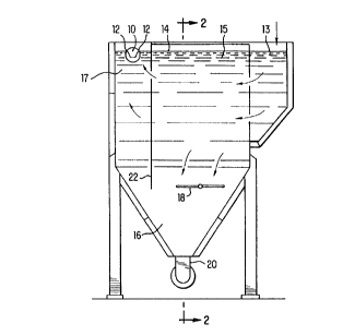
Figure 1 is a sectional view of a first embodiment of the present
invention;
CA 02161314 1999-O1-07
6
Figure 2 is a sectional view of inclined parallel
plates taken along section line 2-2 of Figure 1;
Figure 3 is a sectional view of a second
embodiment of the present invention;
Figure 4 is a plan view of a third embodiment of
the present invention;
Figure 5 is a sectional view of a fourth
embodiment of the present invention;
Figure 6 is a plan view of a treatment system of
the present invention;
Figure 7 is a plan view of another treatment
system of the present invention;
Figure 8 is a sectional view of a treatment tank
of the present invention; and
Figure 9 depicts flow conditions for settling and
settling/storage treatment tanks used in a system of the
present invention.
DETAILED DESCRIPTION OF THE PREFERRED EMBODIMENTS
A first embodiment of~ a tank of the present
invention will be described with reference to Figures 1
and 2.
The treatment tank has an inlet chamber 13, a
separation chamber 15, an outlet chamber 17 and a sludge
chamber 16. The inlet chamber 13 receives water having
suspended particles and directs the water to the
separation chamber 15 in a generally horizontal flow
direction. The separation chamber 15 includes plural
inclined parallel plates 19 which have flow passages 23
between the plates I9. Particles in the water passing
between the inclined parallel plates 19 settle onto the
surface of the plates 19. Most particles deposited on the
surface of the inclined parallel plates 19 slide down the
surface of the plates 19, fall off the ends of the
plates 19, and settle on the bottom of the tank in a
sludge chamber 16.
The water exiting from the separation chamber 15
enters the outlet chamber 17 in a generally horizontal
flow direction. Particles which have not settled on the
2~.~~-~~~~
surface of the parallel plates 19 gradually fall within
the outlet chamber 17 down to the sludge chamber 16.
An outlet channel 10 is provided in the outlet
chamber 17. There are outlet weirs 12 on each side of the
outlet channel 10 so that the surface layer 14 of water
can overflow the outlet weirs 12 into the outlet channel
to form an outflow.
The treatment tank also includes a gas
distribution pipe 18 which is located underneath the
separation chamber 15. The gas distribution pipe 18 has
plural apertures to introduce a gas such as air from the
pipe as bubbles. The gas distribution pipe 18 provides a
periodic burst of air bubbles which travel from the air
distribution pipe 18 up through the gaps between the
inclined parallel plates 19 and eventually to the surface
of the treatment tank. The passage of the bubbles through
the gaps between the plates 19 dislodges particles clogged
between the plates 19. While air is preferred, any gas
could be used. Air is not necessary because the air
(oxygen) bubbles are not intended to promote aerobic
treatment. Rather, any gas could be used because the
bubbles are intended to dislodge trapped particles while
the outf low is interrupted.
The treatment tank may also be provided with a
sludge exit pipe 20 which allows the particles collected
in the sludge chamber 16 to be discharged from the tank
for disposal. A sludge valve 21 may be provided in the
sludge exit pipe 20 to selectively control the flow of
sludge out of the tank. When particles in the sludge
chamber 16 are discharged from the tank, the water volume
in the tank is decreased. This means that the surface
layer 14 of the water in the outlet chamber 17 will drop
below the tops of the outf low weirs 12 , interrupting the
out f low .
A controller may be provided to cause bubbles to
be emitted from the gas distribution pipes 18 during a
period when the surface layer 14 of water in the tank is
below the outlet weirs and the outflow is interrupted to
2~ ~~..o~~~_
8
ensure that particles that are stirred up by the bubbles
do not enter the outflow. Water may still be introduced
into the inlet chamber during this period.
The treatment tank may also include a baffle 22
which extends the length of the treatment tank underneath
the separation chamber 15. The baffle 22 prevents a short
circuit of water from flowing underneath the separation
chamber 15 and directly into the outlet chamber 17. This
ensures that all water entering the inlet chamber 13 flows
through the separation chamber 15 before reaching the
outlet chamber 17.
It is possible to alter the treatment tank shown
in Figures 1 and 2 so that two separated sets of inclined
parallel plates are provided in the tank. The width of
the separation chamber includes the width of both sets of
inclined parallel plates.
The second embodiment of the treatment tank, shown
in Figure 3, has all of the features of the first
embodiment and additionally includes a collection chamber
25 located between the separation chamber 15 and the
outlet chamber 17. A baffle 27, extending the full length
of the tank, separates the collection chamber 25 from the
outlet chamber 17. A collection channel 26, having two
collection weirs 28, is provided in the collection chamber
25.
The water exiting the separation chamber 15 is
provided in a generally horizontal flow direction to the
outlet chamber 17. Contaminants such as oil, which are
lighter than water, will float to the surface of the
collection chamber 25. Since the collection weirs 28 are
adjusted slightly under the water level in chamber 17,
floating contaminates such as oil can consequently be
discharged over the top of the collection weirs 28 into
the collection channel 26 to form a contaminant outflow.
The discharge from the channel 26 can be arranged either
as a continuing outflow, or as a sequenced outflow
automatized by a timer and a shut-off valve.
9
The baffle 27 prevents contaminants floating on
the surface layer 24 from entering the outlet chamber 17.
Water must pass underneath the baffle 27 to reach the
outlet chamber 17. This ensures that contaminants that
are lighter than water, and that float toward the surface
of the collection chamber 25, should not reach the outlet
chamber 17.
A third embodiment of a treatment tank of the
present invention, shown in the plan view of Figure 4,
includes an inlet chamber 13 that introduces water into a
central portion of a cylindrical treatment tank. The
water in the inlet chamber 13 is divided into two parallel
distribution channels 13a and 13b, from which the flow is
distributed in a generally horizontal flow in two opposite
directions towards the sides of the treatment tank.
The treatment tank has two separation chambers 15,
each having a plurality of inclined parallel plates.
Water from the inlet chamber 13 enters the separation
chambers 15 in a generally horizontal flow direction and
passes through the gaps between the inclined parallel
plates of the separation chambers 15. Particles in the
water settle onto the surface of the plates, glide down
the plates, and fall to a common sludge chamber in the
bottom of the treatment tank.
Water leaving the separation chambers 15 enters
the outlet chambers 17 on the sides of the treatment tank.
Outlet channels 10 are provided in each of the outlet
chambers 17, and each outlet channel 10 includes two
outlet weirs 12.
A treatment tank as shown in Figure 4 employs two
arc-shaped outlet channels, each having two outlet weirs.
This further increases the total length of the outlet
weirs so that the overflow rate of water flowing over the
outlet weirs, per unit length of the outlet weirs, is
minimized, and the quality of the outflow is maximized.
In a fourth embodiment of the present invention,
shown in Figure 5, water is introduced to the tank in a
central portion in two opposite, relatively horizontal
10
directions through an inlet chamber 13. The water flows
through gaps between inclined parallel plates of two
separation chambers 15 and enters outlet chambers 17.
Outlet channels 10 are provided in each of the
outlet chambers 17. Each outlet channel 10 extends for
the length of the tank and includes two outlet weirs 12,
one on each side of the outlet channel.
Air distribution pipes 18 are provided underneath
the separation chambers 15. During a plate rinsing cycle
air bubbles emitted from the air distribution pipes 18
travel up through the gaps between the plates in the
separation chambers 15 to dislodge particles clogged
between the plates.
Flow baffles 22 may be provided underneath the
separation chambers 15 to prevent water from flowing under
the separation chambers 15, and flowing directly into the
outlet chambers 17. The baffles 22 ensure that water
entering the tank through the inlet chamber 13 must pass
through the separation chambers 15.
Scraper blades 32 may be provided in sludge
chambers 16 underneath the separation chambers 15 and
outlet chambers 17. The scraper blades scrape collected
particles toward a sludge collection point.
An embodiment of a complete storm water treatment
and storage system of the present invention is shown in
Figure 6. In this embodiment, the treatment tanks employ
the same crossflow design as shown in Figures 1-5.
The system has one or several settling treatment
tanks located close to each other in the system. An inlet
valve 44 controls the flow rate of water entering the
settling treatment tank. The water enters the settling
treatment tank A through an inlet chamber 50 and flows in
opposite horizontal directions through the separation
chambers 52 where particles settle onto the inclined
parallel plates. Water overflows outlet weirs on outlet
channels 54, to form an outflow, and the outflow is
directed into a common outlet channel 64.
2~.~~.'~ ~-
Settling/storage treatment tanks B are provided
close to the settling treatment tanks A within the same
tank system. The settling/storage treatment tanks are
also of the crossflow design depicted in Figures 1-5. The
settling/storage treatment tanks B may be physically
identical to the settling treatment tanks A except for
discharge pumps 62 and inlet arrangements 48 and 59.
When the flow rate of water entering the system
exceeds the maximum designed flow rate of the settling
treatment tank A, the flow rate into the settling
treatment tank A is limited by the inlet valve 44 to the
maximum designed flow rate. Excess water collects in the
inlet area 42. When the water level has risen high enough
in the inlet area 42, it begins to overflow inlet weirs 48
and enters settling/storage inlet areas 49. Water in the
settling/storage inlet areas 49 is then selectively routed
to the inlet chambers 58 of the settling/storage treatment
tanks via gates 59.
Water is introduced into the settling/storage
treatment tanks B through the inlet chambers 58 of the
settling/storage treatment tanks B. Like the settling
tank A, water in the settling/storage tanks B flows in
opposite horizontal directions through the separation
chambers 60 of the settling/storage treatment tanks B.
Particles settle on the inclined parallel plates of the
separation chambers 60, and the water overflows outlet
weirs into outlet channels 66 to form an outflow, the
outflow joining the outflow from the settling treatment
tank A in the common outlet channel 64.
A sectional view of a settling/storage treatment
tank is shown in Figure 8. The sectional view shows the
inclined parallel plates of one of the separation chambers
60. Water passes through the gaps between the inclined
parallel plates of the separation chamber 60 and particles
settle onto the surface of the plates. The particles
glide down the plates and fall into the sludge chambers
16. The water flow into the inlet chamber of the
settling/storage treatment tank is controlled by a gate
2'1~1~~_~
12
59, which is raised or lowered to control entry of water
into the inlet chamber of the settling/storage treatment
tank.
A pump 62 is provided in the settling/storage
treatment tank for pumping stored water from the
settling/storage treatment tank to the inlet area of the
settling treatment tank after storm events. Sludge pipes
72 extend from near the bottom of the sludge chambers 16
out of the settling/storage treatment tank. When the
sludge chamber 16 becomes full of collected particles, the
particles can be discharged out of the tank through the
sludge pipes 72.
Operation sequences of the settling and
settling/storage treatment tanks of a system of the
present invention are shown in Figure 9. The lefthand
column of treatment tanks represents a settling treatment
tank and the righthand column represents a
settling/storage treatment tank.
In sequence 1, the flow (e. g., stormwater and/or
combined sewer overflow) entering the system at the start
of a storm event is treated in the settling treatment
tank. All the water entering the system is routed to the
inlet of the settling treatment tank, flows through the
separation chambers of the settling treatment tank, and is
collected in the outlet channel of the settling treatment
tank. Since the settling/storage treatment tank is not
needed, it remains empty.
In sequence 2, which is the next stage of the
storm event, the amount of water entering the system
exceeds the predefined maximum flow rate for the settling
treatment tank. In this condition, the flow rate of water
entering the settling treatment tank is regulated so that
the overflow of the settling treatment tank has a desired
water quality. Any excess flow (i.e., flow which the
settling tank cannot accept) is directed into the
settling/storage treatment tank. The settling/storage
treatment tank will gradually begin to fill up, but no
water will exit the settling/storage treatment tank until
~1~~ ''°~.~
13
the water level in the settling/storage treatment tank is
high enough to overflow the outlet weirs of the outlet
channel.
In sequence 3, the water level in the
settling/storage treatment tank is high enough to overflow
the outlet weirs, and both the settling and
settling/storage treatment tanks are providing an outflow
of treated water. Particles are collected in the bottom
of the settling and settling/storage treatment tanks in
the sludge chambers.
Sequence 4 represents the next step when the
stormwater is decreasing at the last part of the storm
event. From this sequence on it is possible to start the
discharge of the accumulated sludge through the sludge
exit pipes. When sludge is removed from the settling and
settling/storage treatment tanks, the water level in the
tanks is lowered below the top of the outlet weirs, and
the water overflowing the outlet weirs to create the
outflow is interrupted. The sludge may be pumped from
both the settling and settling/storage treatment tanks
simultaneously so that the outflows from the entire system
is interrupted, or sludge may be pumped from a single
treatment tank at a time so that an outflow is maintained,
but at a decreased rate. The air distribution pipes (not
shown in Fig . 9 , but i l lustrated in Figs . 1, 2 , 3 and 5 )
can be activated at this time to dislodge clogged
particles on the plates.
In sequence 5, the storm event is over and there
is no water flowing into the system. The water volume in
the settling/storage tank is now pumped to the settling
tanks for treatment. Consequently, the settling/storage
tanks are emptied and are ready to start the next filling
sequence when the next storm event occurs.
Another embodiment of the treatment system of the
present invention is shown in Figure 7. In this
embodiment, the treatment tanks are pie-shaped segments
which allow for a compact system. The pie-shaped tanks
have the same structure and function as the rectangular
2~.~~ ~~~_
14
tank system shown in Figure 6. However, the pie-shaped
tanks offer more equal flow distribution to the separate
tanks than the rectangular tanks. The separation chambers
52 , 60 are located between the inlet chambers 52 , 58 and
the outlet channels 64, 66.
Water enters the system through a main inlet area
42 and is directed to the settling treatment tanks A
through inlet flow valves 44 which limit the flow rate
entering the settling treatment tanks A. Water enters the
settling treatment tanks through inlet chambers 50, passes
through separation chambers 52, then overflows outlet
weirs into outlet channels 54 to form an outflow.
Chambers for disinfection and/or chemical
treatment 70 may be provided as part of the treatment
tanks. The chambers 70 communicate with the outlet
channels 54 of the treatment tanks. Chemicals may be
introduced into the outflow in the chambers 70 for
disinfection and/or chemical treatment of the outflow.
After passing through the chambers 70 for disinfection
and/or chemical treatment the treated water exits the
settling treatment tanks A and is collected in a common
outlet channel 64.
The inlet flow valves 44 limit the flow rate of
water entering the settling treatment tanks A. When the
flow rate of the water increases to the level where the
settling treatment tanks can no longer treat all the flow,
the water level in the inlet area 42 rises and eventually
overflows inlet weirs 48. Water flowing over the inlet
weirs 48 enters the settling/storage inlet areas 49, and
is directed through the settling/storage treatment tanks
B. When the water level is high enough, water flows
through the separation chambers 60 of the settling/storage
treatment tanks B, overflows outlet weirs, and is
collected in the outlet channels 66 of the
settling/storage treatment tanks B to form an outflow. As
in the settling treatment tanks A, chambers 70 for
disinfection and/or chemical treatment may be provided in
the settling/storage treatment tanks B. The outflow of
_ .
the settling/storage treatment tanks is joined with the
outflow from the settling treatment tanks in the common
outlet channel 64.
Inclined parallel plates are used in many
treatment tanks for removing large particles with good
settling characteristics. When it is necessary to remove
small, light particles with poor settling characteristics,
or sticky particles that tend to adhere to and clog the
plates, the inclined parallel plate systems have serious
disadvantages. Either the particles do not settle toward
the bottom before overflowing the outlet weirs, or the
particles clog between the plates, necessitating frequent
removal and cleaning of the plates.
The tanks and systems of the present invention
eliminate these drawbacks so that inclined parallel plate
treatment systems can be used in a broader variety of
applications. The air distribution pipes provide bubbles
that release particles clogged between the plates without
any necessity to remove the plates from the tank for
separate cleaning, and without causing any escape of
rinsed particles over the outlet weirs. Providing outlet
weirs on both sides of the outlet channels, and extending
the weirs for the entire length of a treatment tank,
maximizes the length of the outlet weirs. This, in turn,
allows the overflow rate of water per unit length of the
outlet weirs to be minimized for a given tank flow rate.
The low overflow rate per unit length of the outlet weirs
also allows a system of the present invention to be used
to effectively treat large flows with low particle
concentrations.
While the invention has been described in connec-
tion with the preferred embodiments, it will be understood
that it is not intended to limit the invention to these
embodiments. On the contrary, it is intended to cover all
alternatives, modifications and equivalents as may be
included within the spirit and scope of the invention as
defined by the appended claims.