Language selection

Search

Patent 2161396 Summary

Third-party information liability

Some of the information on this Web page has been provided by external sources. The Government of Canada is not responsible for the accuracy, reliability or currency of the information supplied by external sources. Users wishing to rely upon this information should consult directly with the source of the information. Content provided by external sources is not subject to official languages, privacy and accessibility requirements.

Claims and Abstract availability

Any discrepancies in the text and image of the Claims and Abstract are due to differing posting times. Text of the Claims and Abstract are posted:

  • At the time the application is open to public inspection;
  • At the time of issue of the patent (grant).
(12) Patent: (11) CA 2161396
(54) English Title: PIG INJECTOR
(54) French Title: INJECTEUR EN FONTE BRUTE
Status: Expired
Bibliographic Data
(51) International Patent Classification (IPC):
  • F16L 55/46 (2006.01)
(72) Inventors :
  • ELLETT, JAMES RICHARD (Canada)
(73) Owners :
  • ARGUS MACHINE CO. LTD. (Canada)
(71) Applicants :
  • ARGUS MACHINE CO. LTD. (Canada)
(74) Agent: LAMBERT INTELLECTUAL PROPERTY LAW
(74) Associate agent:
(45) Issued: 2004-12-28
(22) Filed Date: 1995-10-25
(41) Open to Public Inspection: 1997-04-26
Examination requested: 2000-05-30
Availability of licence: N/A
(25) Language of filing: English

Patent Cooperation Treaty (PCT): No

(30) Application Priority Data: None

Abstracts

English Abstract


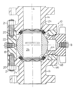
A pig injector has a valve assembly having
a pair of valve seats. A valve ball having a bore is
disposed within the valve assembly and seated on the
valve seats. A journalled stem mounted in a stuffing
box is provided to rotate the valve ball within the
valve assembly between a position in which the bore is
aligned along the pipe and a position in which the
bore is aligned across the pipe. A side entry cap is
disposed in the valve assembly in alignment with the
bore of the valve ball when the bore is aligned across
the pipe. The side entry cap includes a threaded
portion and a sealing portion, the threaded portion
being cylindrical and the sealing portion having an
exterior surface forming a conical section increasing
in diameter with increasing distance from the bore of
the valve ball. The valve assembly has a corresponding
conical seat portion for receiving the conical section
of the side entry cap in sealing relationship. An
annular groove is formed in one of the conical section
of the sealing portion and the conical seat portion of
the valve assembly, the annular groove being defined
by walls extending inward from the respective one of
the conical section of the sealing portion and the
conical seat portion of the valve assembly. An annular
sealing element is disposed within the annular groove.


French Abstract

Injecteur à racleur ayant un ensemble de valve comprenant une paire de sièges de valve. Un clapet ayant un alésage est disposé au sein de l’ensemble de valve et siège sur les sièges de valve. Une tige tourillonnée montée dans une boîte à garniture est prévue pour faire tourner le clapet au sein de l’ensemble de valve entre une position dans laquelle l’alésage est aligné le long du tuyau et une position dans laquelle l’alésage est aligné en travers du tuyau. Un capuchon d’entrée latérale est disposé dans l’ensemble de valve en alignement avec l’alésage du clapet lorsque l’alésage est aligné en travers du tuyau. Le capuchon d’entrée latérale inclut une portion filetée et une portion d’étanchéité, la portion filetée étant cylindrique et la portion d’étanchéité ayant une surface extérieure formant une section conique dont le diamètre augmente avec la distance par rapport à l’alésage du clapet. L’ensemble de valve comprend une portion de siège conique correspondante destinée à recevoir la section conique du capuchon d’entrée latérale en relation d’étanchéité. Une rainure annulaire est formée dans un élément parmi la section conique de la portion d’étanchéité et la portion de siège conique de l’ensemble de valve, la rainure annulaire étant définie par des parois s’étendant vers l’intérieur depuis l’élément respectif parmi la section conique de la portion d’étanchéité et la portion de siège conique de l’ensemble de valve. Un élément d’étanchéité annulaire est disposé au sein de la rainure annulaire.

Claims

Note: Claims are shown in the official language in which they were submitted.


8

THE EMBODIMENTS OF THE INVENTION IN WHICH AN EXCLUSIVE
PROPERTY OR PRIVILEGE IS CLAIMED ARE DEFINED AS
FOLLOWS:

1. A pig injector for injecting pigs into a
pipe, the pig injector comprising:
a valve assembly having a pair of valve
seats;
a valve ball disposed within the valve
assembly and seated on the valve seats, the valve ball
having a bore;
means to rotate the valve ball within the
valve assembly between a position in which the bore is
aligned along the pipe and a position in which the
bore is aligned across the pipe;
a side entry cap disposed in the valve
assembly in alignment with the bore of the valve ball
when the bore is aligned across the pipe;
the side entry cap including a threaded
portion and a sealing portion, the threaded portion
being cylindrical and the sealing portion having an
exterior surface forming a conical section increasing
in diameter with increasing distance from the bore of
the valve ball;
the valve assembly having a corresponding
conical seat portion for receiving the conical section
of the side entry cap in sealing relationship;
an annular groove formed in one of the
conical section of the sealing portion and the conical
seat portion of the valve assembly, the annular groove
being defined by walls extending inward from the
respective one of the conical section of the sealing
portion and the conical seat portion of the valve
assembly; and


9

an annular sealing element disposed within
the annular groove.

2. The pig injector of claim 1 in which the
annular groove is formed in the sealing portion of the
side entry cap.

3. The pig injector of claim 2 in which the
side entry cap has a central axis and the side walls
of the annular groove are perpendicular to the central
axis.

4. The pig injector of claim 3 in which the
annular sealing element is made of a plastic
chemically inert material.

5. The pig injector of claim 4 in which the
annular sealing element is made of
tetrafluoroethylene.

6. The pig injector of claim 1 in which the
annular groove is formed in the valve assembly.

7. The pig injector of claim 6 in which the
side entry cap has a central axis and the side walls
of the annular groove are perpendicular to the central
axis.

8. The pig injector of claim 7 in which the
annular sealing element is made of a plastic
chemically inert material.


10

9. The pig injector of claim 8 in which the
annular sealing element is made of
tetrafluoroethylene.


Description

Note: Descriptions are shown in the official language in which they were submitted.


2161396
1
TITLE OF THE INVENTION:
Pig Injector
NAME OF INVENTOR:
James Richard Ellett
FIELD OF THE INVENTION
This invention relates to pig injectors.
BACKGROUND OF THE INVENTION
Pig injectors for pipes are known that
include a valve body having a pair of valve ball
seats, a valve ball disposed within the valve body and
seated on the valve ball seats, the valve ball having
a bore and means to rotate the valve ball within the
valve body between a position in which the bore is
aligned along the pipe and a position in which the
bore is aligned across the pipe and a side entry cap
sealed to the valve body. An example is the model SSB
3" pigging valve of Barber Industries Ltd. of Calgary,
Alberta, Canada.
This pig injector suffers disadvantages. The
sealing mechanism of the side entry cap includes an
annular groove formed in an outward facing wall of the
valve body. An elastomeric O-ring sits in the annular
groove, and the annular groove has a dovetail side to
help hold it in. This seal design suffers several
problems. The O-ring is prone to contraction or
expansion and may fall out. In addition, Teflon
(tetrafluoroethylene) or other similar stiff plastic
chemically inert materials cannot be used for the O-
ring as it is difficult to squeeze it past the inward
facing edge of the narrow entry dovetail groove.


2161396
2
SUI~1ARY OF THE INVENTION
There is therefore provided in accordance
with a broad aspect of the invention, a pig injector
comprising a valve body having a pair of valve ball
seats; a valve ball disposed within the valve body and
seated on the valve seats, the valve ball having a
bore; means to rotate the valve ball within the valve
body between a position in which the bore is aligned
along the pipe and a position in which the bore is
aligned across the pipe; a side entry cap disposed in
the valve body in alignment with the bore of the valve
ball when the bore is aligned across the pipe; the
side entry cap including a threaded portion and a
sealing portion, the threaded portion being
cylindrical and the sealing portion having an exterior
surface forming a conical section increasing in
diameter with increasing distance from the bore of the
valve ball; the valve body having a corresponding
conical seat portion for receiving the conical section
of the side entry cap in sealing relationship; an
annular groove formed in one of the conical section of
the sealing portion and the conical seat portion of
the valve body, the annular groove being defined by
walls extending inward from the respective one of the
conical section of the sealing portion and the conical
seat portion of the valve body; and an annular sealing
element disposed within the annular groove. The walls
of the groove are preferably oriented perpendicularly
to the axis of the side entry cap. This configuration
in effect performs the desired influence of inhibiting
the displacement of the O-ring from the groove because
of the dovetail action on the depressurized side.
The annular groove formed in a conical seat,
preferably on the valve body, allows a metal to metal


261396
3
seal to be made simultaneously between the valve body
and the side entry cap when the annular sealing
element is compressed by contact with the conical
section of the side entry cap. The groove in the
conical seat helps prevent the annular sealing element
from escaping the groove due to expansion or
contraction. Also, for the annular sealing element to
escape the groove it would be required to compress
circumferentially to a greater extent than is probable
due to hydrostatic pressure acting upon it. The
parallel sides of the groove allows a Teflon"
(tetrafluoroethylene) ring or the like to be used as
the annular sealing element.
BRIEF DESCRIPTION OF THE DRAWINGS
There will now be described preferred
embodiments of the invention, with reference to the
drawings, by way of illustration, in which like
numerals denote like elements and in which:
Fig. 1 is a section through a pig injector
with valve ball and side entry cap according to the
invention, with the section perpendicular to the axis
of rotation of the valve ball;
Fig. lA is a section through a pig injector
with valve ball and side entry cap according to the
invention, with bore of the valve ball aligned with
the side entry cap;
Fig. 2 is a section through a pig injector
with valve ball and side entry cap according to the
invention, with the section parallel to the axis of
rotation of the valve ball;
Fig. 3 is a section showing a detail of a
valve seat and sealing element for the valve ball;


2 i 61396
4
Fig. 4 is a section showing a detail of a
second, but not preferred, embodiment of a side entry
cap according to the invention, this embodiment not
being preferred because it does not have all of the
advantages of the embodiment shown in Figs. l, 2 and
5; and
Fig. 5 shows a detail of an annular groove
according to the invention.
DETAILED DESCRIPTION OF PREFERRED EMBODIMENTS
The term "inward" in relation to a part
means into the bulk of the material, that is, away
from an adjacent surface.
Referring to Figs. 1, lA and 2, there is
shown a pig injector according to the invention. The
pig injector is formed of a valve assembly 10 that
attaches between portions of a pipe (not shown) in
conventional fashion using studs (not shown). The
valve assembly 10 is formed of a first tail piece 14,
a second tail piece 16 and a center piece 18. First
tail piece 14 and second tail piece 16 are bolted
together around the center piece 18 using studs 20 and
nuts 21 and form a part of the pipe to which the pig
injector is attached. Flow through the pipe
establishes the direction "along" the pipe. A valve
ball 22 is disposed within the valve assembly 10 and
seated on valve seats generally indicated at 24. The
valve ball 22 has a bore 26 passing entirely through
the valve ball.
Referring in particular to Fig. 2, there is
shown means to rotate the valve ball 22 within the
valve assembly 10 between a position in which the bore
26 is aligned along the pipe (as shown in Fig. 1) and
a position in which the bore is aligned across the


CA 02161396 2003-12-19
5
pipe (as shown in Fig. 1A). The means to rotate the
valve ball 22 includes a stuffing box 28 fastened into
the side of the pig injector using four ferry
capscrews 30 and a stop spacer 33 with associated stop
5 32. The stuffing box 28 is sealed to the body center
piece 18 using O-ring 31. A stem 34 is journalled
within the stuffing box 28 on bearings 36, secured
within the stuffing box by snap ring 38 and shoulder
41 and sealed using seals 42 and 44. The stem 34 is
1o connected to the valve ball 22 by plate 46.
Each valve seat 24, shown in more detail in
Fig. 3, is formed of an annular sealing element 50
(for example made of nylon or other relatively stiff
plastic, such as NylatronT~, a nylon with molybdenum
15 sulphide) riding on a shoulder 51 of valve tail piece
16. A steel retaining ring 52 holds the sealing
element 50 in place. An O-ring seal 54 rests in a
groove 56 in shoulder 51, and seals against the
sealing element 50. A spring 58 urges the sealing
2o element 50 into contact with valve ball 22. A TeflonTM
or other similar stiff plastic chemically inert
material in the shape of a flat barrier ring 55
isolates the O-ring 54 from the tailpiece 14 or 16.
This prevents scrubbing away of corrosion products and
25 causes pitting and subsequent leakage.
On one side of the valve ball body 22 is a
side entry cap 60 with lugs 61 for injecting pigs
into and receiving pigs from the pipeline to which
the valve body is attached. The side entry cap 60 is
3o disposed in the valve assembly 10 in alignment with
the bore 26 of the valve ball 22 when the bore 26 is
aligned across the pipe (when rotated 90~ from the
position shown in Fig. 1) . The side entry cap 60 is
formed of a plug 62 having a cylindrical threaded


2161396
6
portion 64 that threads into corresponding threads 66
on the valve assembly 10, and a conical sealing
portion 68. The sealing portion 68 has an exterior
surface forming a conical section increasing in
diameter with increasing distance from the bore of the
valve ball 22. The valve assembly 10 has a
corresponding conical cap seat 70 whose exterior
surface is machined at the same conical angle as the
conical section of the side entry cap 60. An annular
groove 72, 74 is formed in one of the conical cap seat
70 (Figs. 1 and 2) and the sealing portion 68 (Fig. 4)
respectively. The annular grooves 72, 74 are defined
by walls 80 (Fig. 5 in particular) extending inward
from the surface in which they are formed. In the case
of annular groove 72, this is inward from the surface
of the cap seat 70, and in the case of annular groove
74, this is inward from the surface of the sealing
portion 68. These walls 80 are preferably
perpendicular to the axis B of the side entry cap 60,
but a less preferred option is to have the side walls
80 perpendicular to the face of the conical section as
shown in Fig. 4. Annular sealing elements 76, 78,
which may be O-rings made of Tef lonT"~
(tetrafluoroethylene) or other plastic chemically
inert material, are disposed within the annular
grooves 72, 74 respectively in conventional sealing
fashion.
The preferred conical angle of the sealing
portion 68 and conical seat 70 to the side entry cap
axis B is about 15°. This permits a good seal between
the respective conical portions of the valve body
center piece 18 and the side entry cap 60, without the
plug 62 damaging the annular sealing element 76 or 78
as the plug 62 is threaded into the valve body 18.


2161396
A person skilled in the art could make
immaterial modifications to the invention described in
this patent without departing from the essence of the
invention.

Representative Drawing
A single figure which represents the drawing illustrating the invention.
Administrative Status

For a clearer understanding of the status of the application/patent presented on this page, the site Disclaimer , as well as the definitions for Patent , Administrative Status , Maintenance Fee  and Payment History  should be consulted.

Administrative Status

Title Date
Forecasted Issue Date 2004-12-28
(22) Filed 1995-10-25
(41) Open to Public Inspection 1997-04-26
Examination Requested 2000-05-30
(45) Issued 2004-12-28
Expired 2015-10-26

Abandonment History

There is no abandonment history.

Payment History

Fee Type Anniversary Year Due Date Amount Paid Paid Date
Application Fee $0.00 1995-10-25
Registration of a document - section 124 $0.00 1996-01-11
Maintenance Fee - Application - New Act 2 1997-10-27 $100.00 1997-10-21
Maintenance Fee - Application - New Act 3 1998-10-26 $100.00 1998-10-01
Maintenance Fee - Application - New Act 4 1999-10-25 $100.00 1999-09-21
Request for Examination $400.00 2000-05-30
Maintenance Fee - Application - New Act 5 2000-10-25 $150.00 2000-10-11
Maintenance Fee - Application - New Act 6 2001-10-25 $150.00 2001-10-17
Maintenance Fee - Application - New Act 7 2002-10-25 $150.00 2002-10-04
Maintenance Fee - Application - New Act 8 2003-10-27 $150.00 2003-09-10
Final Fee $300.00 2004-09-08
Maintenance Fee - Application - New Act 9 2004-10-25 $200.00 2004-10-05
Maintenance Fee - Patent - New Act 10 2005-10-25 $250.00 2005-10-14
Back Payment of Fees $250.00 2006-10-19
Maintenance Fee - Patent - New Act 11 2006-10-25 $250.00 2006-11-15
Expired 2019 - Late payment fee under ss.3.1(1) 2007-02-05 $62.50 2006-11-15
Maintenance Fee - Patent - New Act 12 2007-10-25 $250.00 2007-08-01
Maintenance Fee - Patent - New Act 13 2008-10-27 $250.00 2008-08-06
Maintenance Fee - Patent - New Act 14 2009-10-26 $250.00 2009-09-03
Maintenance Fee - Patent - New Act 15 2010-10-25 $450.00 2010-10-01
Maintenance Fee - Patent - New Act 16 2011-10-25 $450.00 2011-10-05
Maintenance Fee - Patent - New Act 17 2012-10-25 $450.00 2012-10-02
Maintenance Fee - Patent - New Act 18 2013-10-25 $450.00 2013-10-04
Maintenance Fee - Patent - New Act 19 2014-10-27 $450.00 2014-10-02
Owners on Record

Note: Records showing the ownership history in alphabetical order.

Current Owners on Record
ARGUS MACHINE CO. LTD.
Past Owners on Record
ELLETT, JAMES RICHARD
Past Owners that do not appear in the "Owners on Record" listing will appear in other documentation within the application.
Documents

To view selected files, please enter reCAPTCHA code :


To view images, click a link in the Document Description column. To download the documents, select one or more checkboxes in the first column and then click the "Download Selected in PDF format (Zip Archive)" or the "Download Selected as Single PDF" button.

List of published and non-published patent-specific documents on the CPD .

If you have any difficulty accessing content, you can call the Client Service Centre at 1-866-997-1936 or send them an e-mail at CIPO Client Service Centre.


Document
Description 
Date
(yyyy-mm-dd) 
Number of pages   Size of Image (KB) 
Representative Drawing 1998-03-27 1 35
Cover Page 1996-03-15 1 14
Abstract 1996-03-15 1 36
Description 1996-03-15 7 248
Claims 1996-03-15 3 62
Drawings 1996-03-15 5 137
Claims 2003-12-19 3 63
Description 2003-12-19 7 247
Cover Page 1998-07-09 1 14
Representative Drawing 2004-03-04 1 18
Cover Page 2004-11-24 1 53
Fees 2005-10-20 1 26
Correspondence 2005-12-01 3 75
Correspondence 2004-09-08 1 24
Assignment 1995-10-25 5 191
Prosecution-Amendment 2000-05-30 1 35
Prosecution-Amendment 2000-10-11 1 40
Prosecution-Amendment 2003-06-19 2 76
Fees 2003-09-10 1 24
Correspondence 2006-02-24 10 17
Correspondence 2005-10-27 1 16
Prosecution-Amendment 2003-12-19 5 204
Fees 2002-10-04 1 24
Fees 2000-10-11 1 25
Fees 1998-10-01 1 35
Fees 1997-10-21 1 37
Fees 2004-10-05 1 28
Fees 2005-10-20 1 26
Fees 2005-10-14 1 25
Correspondence 2006-03-07 3 13
Fees 2006-05-17 8 283
Fees 2006-10-19 1 25
Fees 2006-11-15 2 40
Correspondence 2006-12-27 1 2
Fees 2007-08-01 1 24
Fees 2008-08-06 1 28
Fees 2009-09-03 1 27
Fees 2010-10-01 1 200