Note: Descriptions are shown in the official language in which they were submitted.
~ 094/24943 PCT~S94/03192
21 61 ~S~
Laparo scop i c surg ~ ca 1 stap 1 er
Technical Field
The present invention is directed to surgical
instruments that are inserted through a trocar cannula
during a laparoscopic surgical procedure.
Background
A large number of abdominal surgical
procedures are performed with laparoscopic techniques
in order to avoid a large skin incision. Typically in
laparoscopic surgery, a special needle (e.g. a needle
15 similar to the needle described in U.S. Patent No.
4,808,168 is inserted through the skin, and used to
pressurize the abdominal cavity with an insufflating
gas such as carbon dioxide (CO~).
Once the abdomen is adequately dilated, the
20 needle is removed and a rigid access tube or cannula
with a diameter larger than the pneumoneedle (for
example 5, 10 or 11 mm) is passed through the skin in
generally the same location. To drive the cannula
through the skin, the surgeon places a trocar in the
25 lumen of the cannula to provide a sharp, leading edge
for cutting tissue. The art is replete with trocar and
cannula assemblies, including those shown in U.S.
Patent Noels. 4,535,773, 4,601,710, 4,654,030,
4,902,280, 4,931,042, 5,104,382, 5,116,353 and
30 5,152,754.
The cannula provides access for laparoscopic
surgical tools or instruments such as a tissue tacker,
a stapler or a surgical clip applier. Such instruments
include mechanical tissue engagement devices such as
35 tissue tackers, staples and clips. Examples of such
surgical~instruments are described in U.S. Patent No.'s
--1--
` ~ 216165~
1 5,040,715, 5,084,057, 5,100,420, 5,171,247, 5,171,249,
5,174,487 and 5,176,695.
In particular, U.S. Patent no. 5,040,715 describes
a surgical stapler for placing lateral lines of staples
and making an incision, all through an endoscopic tube,
and including an anvil member which is mounted to the
distal end of the elongated housing. A tubular collar
disposed around the arm of the anvil member is movable
to a distal position to bias the anvil member and a
cartridge assembly into cooperative alignment, thereby
clamping body tissue to be fastened between the anvil
~^~her and cartridge assembly.
It may be difficult to determine whether the
supply of tissue engagement devices in ~n existing
surgical instrument is depleted (e.g. whether the
instrument is spent~, particularly during a
laparoscopic surgical procedure where a surgeon's
attention may be focused elsewhere. U.S. Patent No.'s
5,084,057 and 5,171,247 disclose laparoscopic clip
appliers which have devices which address this problem.
However, valuable time during the lap2roscopic sur~ical
procedure may be wasted by inserting a spent surgical
instrument through the cannula.
A surgical instrument such as a laparoscopic
surgical stapler has jaws for clamping on tissue. If
the jaws are clamped on tissue when the supply of
staples is depleted, the tissue may suffer u~neC~cs~ry
tissue trauma. Further, a laparoscopic stapler
- typically has knife which is inten~e~ to cut between
rows of applied staples. if the staples are not present
and the stapler is fired, the knife blade may cut
tissue that is intended to be closed by the missing
staples, clearly an undesirable result.
~ 3Sh~
Brief ~escriPtion of the Inven~ion
1 According to the present invention ~here is
provided a laparoscopic surgical instrument adapted to
be inserted through a cannula and into the abdominal
cavity of a patient during a laparoscopic surgical
procedure. The laparoscopic-surgical instrument
includes a blocking body that prevents the surgical
instrument from being reinserted into the abdominal
cavity after tissue engagement devices (such as
staples, clips or tissue tackers) within the surgical
instrument are spent.
~161~5g
094/24943 PCT~S94/03192
The blocking body allows the spent surgical
instrument to be removed from the abdominal cavity
through the cannula, but thereafter prevents the
instrument from being reinserted through the cannula.
5 Valuable time during the laparoscopic procedure is not
wasted by inadvertently or accidentally inserting a
spent instrument through the cannula, and tissue is not
unnecessarily traumatized.
According to the present invention, there is
10 provided a laparoscopic surgical instrument such as a
stapler comprising a proximal portion, a distal portion
having at least one mechanical tissue engagement device
(such as staples) , actuation means f or placing the
staples on tissue, an elongate, substantially
15 cylindrical shaft portion between the proximal and
distal portions for abutment with inner surfaces of the
cannula when the stapler within the cannula, and the
blocking body.
The stapler also comprises a means,
20 operatively associated with the actuation means, which
mounts the blocking body for pivotal movement between a
non-blocking position which affords insertion and
removal of the distal portion through the cannula, and
an insertion blocking position in which the blocking
25 body affords removal of the distal portion from the
abdominal cavity, and in which the blocking body
thereafter prevents insertion of the distal portion
through the cannula. The stapler also preferably
comprises biasing means, such as a spring, for urging
30 the blocking body toward the blocking position.
In a preferred embodiment of the present
invention, the means mounting the blocking body for
movement between non-blocking and insertion blocking
positions comprises the distal portion having a latch,
35 and the blocking body having pin for engaging the latch
when the blocking body is in the non-blocking position.
W094/24943 ~ ~ PCT~S94/03192 -
Also preferably, the blocking body comprises a cam
surface for engaging the end of the cannula to afford
removal of the distal portion from the abdominal cavity
through the cannula when the blocking body is in the
5 blocking position, and an obstruction surface for
engaging the cannula to prevent the surgical instrument
from being reinserted through the cannula.
The present invention may also be described
as a laparoscopic surgical procedure comprising the
lO steps of: (1) providing a cannula, (2) inserting a
portion of the cannula into the abdominal cavity of a
patient, (3) providing a laparoscopic instrument having
a distal portion with at least one mechanical tissue
engagement device, an actuation means capable of
15 engaging the mechanical tissue engagement device on
tissue, and a blocking body movable between blocking
and non-blocking positions, (4) inserting the distal
portion of the laparoscopic surgical instrument into
the abdominal cavity of the patient through the
20 cannula, (5) actuating the actuation means until no
mechanical tissue engagement device remains to be
engaged on tissue, and then (6) removing the distal
portion from the abdominal cavity such that, after the
distal portion is removed, the blocking body is in the
25 blocking position in which it thereafter prevents
insertion of the distal portion through the cannula.
Brief Descri~tion of the Drawinqs
The present invention will be further
30 described with reference to the accompanying drawing
wherein like reference numerals refer to like parts in
the several views, and wherein:
Fig. 1 is an exploded perspective view of a
surgical instrument having an articulated jaw
35 structure.
~ 094l24943 21 61 6 5 ~ PCT~S94/03192
Fig. 2 is an assembled side view of the
surgical instrument shown in Fig. 1, showing the jaws
in a fully open position.
Fig. 3 is an assembled side view of the
5 surgical instrument shown in Fig. l, showing the jaws
in an intermediate position.
Fig. 4 is an assembled side view of the
surgical instrument shown in Fig. 1, showing the jaws
in an approximated position, and showing a knife
10 assembly and a knife actuating assembly.
Fig. 5 is an enlarged side view of the knife
assembly and the knife actuating assembly of the
surgical instrument shown in Fig. 4.
Fig. 6 is a top sectional view of the
15 surgical instrument shown in Fig. 4, taken along line
6-6.
Fig. 7 is a front sectional view of the
surgical instrument shown in Fig. 2, taken along line
7-7.
Fig. 8 is a front sectional view of the
surgical instrument shown in Fig. 2, taken along line
8-8.
Fig. 9 is a front sectional view of the
surgical instrument shown in Fig. 2, taken along line
25 9-9.
Fig. lO is a front sectional view of the
surgical instrument shown in Fig. 3, taken along line
10-10 .
Fig. 11 is a front sectional view of the
30 surgical instrument shown in Fig. 3, taken along line
11-11 .
Fig. 12 is a front sectional view of the
surgical instrument shown in Fig. 4, taken along line
12-12.
W094/24943 658 PCT~S94/03192
Fig. 13 is a side view of a first modified
surgical instrument having an articulated jaw structure
showing the jaws in a fully open position.
Fig. 14 is a side view of the surgical
5 instrument shown in Fig. 13, showing the jaws in an
intermediate position.
Fig. 15 is a side view of the surgical
instrument shown in Fig. 13, showing the jaws in an
approximated position.
Fig. 16 is a side view of a second modified
surgical instrument having an articulated jaw
structure, showing the jaws in a fully open position.
Fig. 17 is a side view of the surgical
instrument shown in Fig. 16, showing the jaws in an
15 intermediate position.
Fig. 18 is a side view of the surgical
instrument shown in Fig. 16, showing the jaws in an
approximated position.
Fig. 19 is an enlarged side view of a portion
20 of the surgical instrument shown in Fig. 18, and
showing a knife assembly and a knife actuating
assembly.
Fig. 20 is a partial perspective view of a
third modified surgical instrument having an
25 articulated jaw structure.
Fig. 21 is a rear sectional view of the
surgical instrument shown in Fig. 20 taken along line
21-21.
Figs. 22A-H are enlarged sectional views of a
30 knife assembly and a knife actuating assembly, wherein
the assemblies are shown at various stages of operation
in a surgical instrument.
Fig. 23 is a top view of the knife assembly
and the knife actuating assembly shown in Fig. 22A.
Fig. 24 is a sectional view taken along line
A-A in Fig. 22C.
~ 094l24943 1~1 6S~ PCT~S94/03192
Fig. 25 is a sectional view taken along line
B-B in Fig. 22C.
Fig. 26 is an enlarged sectional view of the
knife assembly.
Fig. 27 is a side sectional view of a
surgical stapler, showing the stapling and cutting of
tissue between the jaws of the stapler.
Figure 28 is a side view of a portion of a
laparoscopic stapler with a blocking body according to
10 the present invention and a trocar cannula, which
illustrates the blocking body in a blocking position.
Figures 29 and 30 sequentially illustrate the
operation of the blocking body according to the present
invention in a laparoscopic surgical stapler wherein:
Figure 29 is a schematic side view which
illustrates the blocking body in a non-blocking
position, and a latch in a latching position; and
Figure 30 is a schematic side view which
illustrates the blocking body in an insertion blocking
20 position, and a latch in an unlatched position.
Petailed Description
A preferred surgical instrument 10 with
articulated jaw structure is shown in pertinent part in
25 Figs. 1-12. Only the distal end of the instrument is
shown, it being appreciated that the surgical
instrument may be actuated using structure and
techniques well known to those skilled in the art.
The surgical instrument 10 includes a tubular
30 frame 12, a first or upper jaw 16 and a second or lower
jaw 18. In surgical stapling apparatus, one of the
jaws (in this case, the lower jaw), may include a
disposable staple cartridge 508. The tubular frame
preferably includes a collar 14. Both the frame and
35 collar are preferably made of stainless steel. The
collar has an end portion 22 defining an opening 23
2l6l~8
W094/~943 PCT~S94/03192
therethrough for receiving the jaws. A pair of
diametrically opposed arms 24 extend axially from the
end portion into the interior of the tubular frame.
Each arm defines an axially extending slot 26. A
5 collar pin 28 is disposed and located by the slots 26
such that the collar pin extends transversely across
the tubular frame. The arms of the collar form a
relatively tight fit against the interior surface of
the tubular frame. A proximal end (not shown) of the
10 tubular frame is mounted to the surgical instrument by
methods well known to those skilled in the art.
The upper jaw 16 has a proximal portion 30
received in the tubular frame and a distal portion 32
that extends out of the end portion 22 of the collar
15 14. The distal portion of the upper jaw has a tissue
contacting surface 34. Similarly, the lower jaw 18 has
a proximal portion 36 received in the tubular frame and
a distal portion 38 that extends out of the end portion
22 of the collar 14. The upper surface of the
20 disposable staple cartridge 508 has a tissue contacting
surface 40.
The jaws are pivotally mounted to each other
such that in an approximated position (FIG. 4), the
tissue contacting surfaces are in opposed relationship
25 to each other. The proximal portion 30 of the upper
jaw 16 is a longitudinally extending bar that defines a
transverse opening 42 for closely receiving the collar
pin 28 located by the collar 14. A proximal end 44 of
the upper jaw is located by a cam 46. The cam is
30 preferably a pin that is disposed parallel to the
collar pin 28, transversely across the tubular frame.
The cam 46 engages a lower camming surface 48 of the
proximal end of the upper jaw. The inside surface of
the tubular frame engages an upper surface 50 of the
35 proximal end of the upper jaw such that the tubular
~ 094/24943 PCT~S94/03192
21 61 6~
frame, the collar pin and the cam vertically locate the
upper jaw.
The proximal portion 36 of the lower jaw 18
is a pair of longitudinally extending members 51 that
5 are located on each side, respectively, of the proximal
portion 30 of the upper jaw (see Figs. 6 and 7). Each
member 51 defines a transverse opening 52 for closely
receiving the collar pin 28 located by collar 14. The
collar pin 28 provides an axis about which the lower
10 jaw may pivot with respect to the upper jaw (see Figs.
6 and 8). A proximal end 54 of each member 51 of the
lower jaw defines a ramped slot 56 that receives the
cam 46 (see Figs. 1, 6 and 9). The cam engages
diagonally extending camming surfaces 58 of the ramped
15 slots. Each diagonally extending camming surface
extends downwardly from the proximal end of the slot to
the distal end of the slot (see Fig. 3). Each of the
longitudinally extending mem~ers 51 of the lower jaw,
at distal ends 60 thereof, defines a ramp 62. An upper
20 portion 64 of each ramp is curved. Below each ramp is
a shoulder 66.
The cam 46 may be fixed to a clevis 67 that
is mounted to the distal end of an actuating rod 68.
Preferably, the actuating rod is axially moveable
25 within the tubular frame to move the cam between first,
second and third positions to be described in more
detail below. A proximal end (not shown) of the
actuating rod is connected to the surgical instrument
by methods known to those skilled in the art for
30 actuation by the operator of the instrument.
With reference now to Figs. 2-4, the
operation of the jaw structure of the surgical
instrument will be described. Fig. 2 shows the jaws in
a fully open position with the cam 46 in a first
35 position A. In the open position, the distal portions
32, 38 of the jaws are fully extended from the tubular
W094/24943 ~ ~ 616 5 ~ PCT~S94/03192
member with the curved upper portion 64 of the ramp of
the lower jaw adjacent to the end portion 22 of the
collar 14. The collar pin 28 is in a first position at
a distal end 72 of the collar arm slots 26. The cam 46
5 is between the lower camming surface 48 of the upper
jaw and a lower end 76 of the ramped slot 56,
preventing counterclockwise rotation of the lower jaw
about the collar pin 28.
Fig. 3 shows the jaws in an intermediate
10 spaced position (see also Fig. 11). By pulling on the
actuating rod 68, the cam 46 is axially retracted from
the first position A at the lower end 76 of the ramped
slot to a second position B at an upper end 78 of the
ramped slot. During the axial retraction, the cam 46
15 engages the diagonally extending camming surface 58 of
the ramped slot to cause the lower jaw to pivot in a
clockwise direction about the collar pin 28 with
respect to the upper jaw. Jaw motion takes place
rapidly relative to the axial movement of the actuating
20 rod. Preferably, movement of the jaws from the fully
open position to the intermediate position is
accomplished with little or no axial movement of the
jaws relative to the tubular member. A high clamping
fDrce between the jaws is unnecessary at this stage of
25 the operation because the jaws are only beginning to
capture tissue between their tissue contacting
surfaces. Notably, in the intermediate position, the
collar pin 28 is still located near the distal end 72
of the collar arm slots 26 and the cam 46 still engages
30 the lower camming surface 48 of the upper jaw.
Further, the lower jaw has moved into a position
wherein further axial movement of the lower jaw will
cause the curved upper portion 64 of the ramp 62 to
contact a lower edge 70 of the opening 23 of the collar
(see also Figs. 1 and 10) . It is the interaction
between the ramp and the collar that will cause the
--10--
094l24943 ~ 6S~ PCT~S94/03192
jaws to approximate in a substantially parallel
relation.
Fig. 4 shows the jaws in an approximated
position wherein the cam 46 has been pulled from the
5 second position B to a third position C. During the
axial retraction, the cam 46 engages the upper end of
the ramped slot 56 which acts as a cam stop 80, forcing
the lower jaw and, correspondingly, the upper jaw
(through the connection at the collar pin 28) to
10 retract axially into the tubular frame. Axial
retraction also causes the jaws to approximate due to
engagement of the ramp 62 with the lower edge 70 of the
opening of the collar (see also Fig. 12).
During the approximating phase of operation,
15 jaw movement takes place slowly in relation to
actuating rod movement. High clamping forces are
desired at this point due to the high force required to
compress the tissue captured between the jaws. High
force multiplication occurs as the ramp 62 bears
20 against the lower edge of the opening of the collar 14.
Notably, in the approximated position, the collar pin
28 has moved to a proximal end 82 of the collar arm
slots 26 and the jaws are fully retracted into the
collar, with the collar contacting the shoulder 66 on
25 the lower jaw adjacent the lower end of the ramp 62.
It will be appreciated that the above
described construction enables the jaws of the
instrument to open widely with relatively little
extension of the jaws beyond the end portion 22 of the
30 collar 14 (as shown by the vertically oriented dashed
line L at the left end of FIGS. 2-4) . This result is
achieved by dividing the jaw closure action into two
parts: a first part, wherein the actuating rod moves
the cam from position A to position B, which requires
35 very little, if any, axial movement of the jaws and, a
second part, wherein the actuating rod moves the cam
W094/24943 ~ 65~ PCT~S94/03192 -
from position B to position C, which does require axial
movement of the jaws. ~otably, the second part of the
jaw closure action is limited to the segment where high
forces are required to compress the captured tissue
5 between the jaws. It will also be appreciated that the
~aws are held substantially parallel over a significant
portion of their operating range, and, in particular,
between their intermediate and approximated positions.
In the preferred embodiment, the ramped slots
10 56 of the lower jaw have a triangular or a
quadrilateral shape. This permits the lower jaw to
move vertically or to rotate relative to the cam 46,
without requiring actuation of the actuating rod by the
operator.
With reference now to Figs. 13-15, a first
modified embodiment 100 of the surgical instrument is
shown having a tubular frame 102, an actuating rod 104,
an upper jaw 106 and a lower jaw 108. In this
embodiment, the collar has been omitted and an
20 elongated clevis 112 has been fixed to the distal end
of the actuating rod 104. The clevis has a distal
portion 114 and a proximal portion 116. The distal
portion 114 defines an axially extending slot 118 for
locating a clevis pin 128 such that the clevis pin
25 extends transversely across the tubular frame 102. A
cam 110, in the form of a pin, is fixably mounted to
the proximal portion 116 of the clevis such that it is
disposed parallel to the clevis pin 128 and
transversely across the tubular frame.
The upper jaw 106 has a proximal portion 130
received in the tubular frame 102 and a distal portion
132 that extends out of a distal end 120 of the tubular
frame. The distal portion of the upper jaw has a
tissue contacting surface 134. Similarly, the lower
35 jaw 108 has a proximal portion 136 received in the
tubular frame and a distal portion 138 that extends out
-12-
~ 094/24943 2 1 61 ~ ~ 8 PCT~S94/03192
from the distal end of the tubular frame. The distal
portion of the lower jaw has a tissue contacting
surface 140.
The jaws are pivotally mounted to each other
5 such that in an approximated position (Fig. 15), the
tissue contacting surfaces are in opposed relationship
to each other. The proximal portion 130 of the upper
jaw 106 is a longitudinally extending bar that defines
a traverse opening 142 for closely receiving the clevis
10 pin 128. A proximal end 144 of the upper jaw defines
an axially extending slot 146 that receives the cam
110. The slot 146 is horizontally disposed in Figs.
13-15.
The proximal portion 136 of the lower jaw 108
15 is a pair of longitudinally extending members 151 that
are located on each side, respectively, of the proximal
portion 130 of the upper jaw. Each longitudinally
extending member 151 defines a transverse opening 152
for closely receiving the clevis pin 128. The clevis
20 pin 128 provides an axis about which the lower jaw may
pivot with respect to the upper jaw. A proximal end
154 of each member 151 of the lower jaw defines a
ramped slot 156 that receives the cam 110. The cam
engages cAmming surfaces 158 of the ramp slots. In
25 Fig. 13, the camming surface extends downwardly from
the proximal end of the slot to the distal end of the
slot. Each of the members 151 of the lower jaw also
defines a ramp 162 at a distal end 160 thereof. An
upper portion 164 of each ramp is curved. Below each
30 ramp is a shoulder 166.
Fig. 13 shows the jaws in a fully open
position with the cam 110 in a first position A and the
distal portions 132, 138 of the jaws fully extended
from end 120 of the tubular frame 102. The cam 110 is
35 at a distal end 122 of the upper jaw slot 146 and at a
distal end 124 of the ramped slot of the lower law 156,
-13-
W094/24943 æ 16 i 6 ~ ~ PCT~S94/03192
preventing counterclockwise rotation of the lower jaw
about the clevis pin 128. The clevis pin 128 is in a
first position at a proximal end 126 of the clevis slot
118. ~pper surfaces or. the proximal portions of both
5 jaws may be configured to contact the interior surface
of the tubular frame.
Fig. 14 shows the jaws in an intermediate
spaced position wherein the cam 110 has been pulled
from the first position A at the distal end 124 of the
10 ramped slot 156 of the lower jaw to a second position B
at a proximal end 131 of the ramped slot. During the
axially retraction, the cam 110 engages the c~rm; ng
surface 158 of the ramped slot to cause the lower jaw
to pivot about the clevis pin 128 in a clockwise
15 direction with respect to the upper jaw. Notably, in
the intermediate position, the clevis pin 128 is now
located at a distal end 127 of the clevis slot 118 and
the cam 110 is located at a proximal end 133 of the
upper jaw slot 146, it being appreciated that the upper
20 and lower jaw slots are now horizontally aligned.
Fig. 15 shows the jaws in an approximated
position wherein the cam 110 has been pulled from the
second position B to the third position C. During the
axial retraction, the cam engages both slot ends of the
25 upper and lower jaw slots, the slot ends acting as a
cam stop 168, forcing the jaws to retract axially into
the tubular frame. Axial retraction further causes the
jaws to approximate due to engagement of the ramp 162
with the end 120 of '_he tubular frame. The lower jaw
30 may also be permitted to rotate about the cam 110
during retraction. Notably, in the approximated
position, the clevis pin 128 is still located at the
distal end 127 of the clevis slot 118. It will be
appreciated that the operation and benefits of the
35 present embodiment are generally similar to that of the
previously described embodiment.
~ 094/24943 21 61 S 5 ~ PCT~S94/03192
With reference now to FIGS. 16-18, a second
modified embodiment 200 of the present invention is
shown wherein only one of the jaws is axially movable.
The surgical instrument includes a frame member 212, an
5 upper jaw 216 and a U-shaped lower jaw 218. The upper
jaw has a proximal portion 230 fixably mounted to the
frame member and a distal portion 232 having a tissue
contacting surface 234. The lower jaw 218 has a
proximal portion 236 mounted to the upper jaw and a
10 distal portion 238 having a tissue contacting surface
240. The jaws are pivotally mounted to each other such
that in an approximated positio~ (FIG. 18), the tissue
contacting surfaces of the jaws are in opposed
relationship to each other.
The proximal portion 230 of the upper jaw
includes an articulating mechanism for opening and
closing the jaws. In particular, the proximal portion
defines three pins arranged parallel to each other and
which protrude transversely from each side of the upper
20 jaw, a first pin 220, a cam pin 222 and a pivot pin
224. A link 228 is pivotally mounted to the pivot pin
224 on each side of the upper jaw. As the link on each
side of the jaw is identical, only one will be
described. A distal end 242 of the link is provided
25 with a link pin 226 that is parallel to the other pins
and extends outwardly from the link. It will be
appreciated that there is a space between the links for
receiving a knife actuating assembly, as more fully
described in connection with FIG. 19.
The proximal portion 236 of the lower jaw has
an articulating mechanism that corresponds to the
articulating ~?chAnism of the upper jaw. In the
preferred embodiment, both upstanding walls of the
U-shaped lower jaw have identical corresponding
35 articulating structure at the proximal portions,
namely, a first slot 244 for receiving the first pin
-15-
5~ --
W094/~943 PCT~S94/03192
220 of the upper jaw and a second slot 246 for
receiving the link pin 226 located at the distal end of
the link 228. The first slot 244 extends diagonally
downward from a proximal end 248 to a distal end 250.
5 The second slot 246 has two portions, a proximal
portion 252 having a mi'd slope relative to the
longitudinal axis of the lower jaw and a distal portion
254 having a steep slope that is preferably disposed at
an angle greater than 90 relative to the longitudinal
10 axis of the lower jaw. The proximal portion of the
lower jaw further includes a cam surface 256 for
engaging the cam pin 222 of the upper jaw. The cam
surface extends diagonally upward towards the proximal
end of the lower jaw.
The distal ends of the links 228 may be
mounted to a clevis 266 of an actuating rod 268 which
is axially movable. Preferably, the clevis is
pivotally mounted to the actuating rod about a traverse
axis parallel to the pins 220, 222, 224, 226. A
20 proximal end (not shown) of the actuating rod is
connected to the surgical instrument by methods known
to those skilled in the art for actuation by the
operator of the instrument. The link pin 226 is
movable between first, second and third positions to be
25 described below in more detail.
The operation of the jaw structure of the
second modified embodiment will now be described. FIG.
16 shows the jaws in a fully open position with the
link pin 226 in a first position A and the lower jaw
30 extended distally relative to the upper jaw. The first
pin 220 is in a first position at the proximal end 248
of the first slot 244 whereas the link pin 226 is at an
upper end 260 of the distal portion 254 of the second
slot. The cam pin 222 is at an upper end 270 of the
35 cam surface 256.
-16-
~ 094/24943 161 6S~ PCT~S94/03192
FIG. 17 show~ the jaws in an intermediate
spaced position wherein the link pin 226 has been
pulled by the actuating rod from the first position A
to a second position B. During the axial retraction,
5 the link 228 rotates in a counterclockwise direction
causing the link pin 226 to ride down the distal
portion 254 of the second slot, pulling the lower jaw
proximally. It is this axial linear motion of the
lower jaw that pulls tissue into the gap between the
10 jaws and inhibits tissue from extruding out of the gap
during approximation. In addition to the axial motion,
the lower jaw also draws closer to the upper jaw due to
its rotation about the link pin 226 as the first pin
220 slides from a first position at the proximal end
15 248 of the first slot to a second position near the
distal end 250 of the first slot. Jaw motion from the
open position to the intermediate position, takes place
rapidly relative to actuating rod movement. A high
clamping force is unnecessary at this stage of the
20 operation because the jaws are only beginning to
capture tissue. Notably, in the intermediate position,
the cam pin 222 is at a lower end 272 of the cam
surface 256.
FIG. 18 shows the jaws in an approximated
25 position wherein the link pin 226 has been pulled by
the actuating rod from the second position B to a third
position C. During the axial retraction, the link pin
226 rides up the proximal portion 252 of the second
slot, causing the lower jaw to close further as it
30 rotates about the first pin 220. During this phase of
the operation, jaw motion takes place slowly in
relation to actuating rod movement. High clamping
force is desired due to the high force required to
compress the captured tissue between the jaws.
35 Notably, in the approximated position, the first pin
220 moves to the distal end 250 of the first slot and
2161~5~ --
W094/249~ PCT~S94/03192
the cam pin 222 remains at the lower end 272 of the cam
surface 256.
It will be appreciated that the cam pin 222
is particularly useful for reopening the jaw structure.
5 In moving from the approximated position to the
intermediate position, the cam pin 222 will engage the
cam surface 256 to urge the lower jaw to its fully
open, extended positior.. A biasing mechanism, such as
a spring 274, may be connected between the proximal
10 portion 236 of the lower jaw and the frame 212 to urge
the lower jaw from its fully open position to the
intermediate position (see Fig. 16).
As with the previously described embodiments,
the second modified embodiment enables the jaws of the
- 15 instrument to open widely with relatively little
extension of the jaws beyond the end of the frame.
Furthermore, the jaws are held substantially parallel
over a significant portion of their opening range and,
in particular, between their intermediate and
20 approximated positions.
With reference to FIGS. 20 and 21, a third
modified embodiment 300 of the present invention is
shown. As with the second modified embodiment, an
upper jaw 310 has a proximal portion 312 that includes
25 an articulating mechanism for operating the jaws. The
proximal portion includes a collar 314 defining a
longitudinally extending opening 316 at the center
thereof. A first pin 320 is mounted to the collar
transversely across the longitudinally extending
30 opening 316. A cam pin 322, parallel to the first pin
320, extends outwardly from each side of the collar. A
pivot pin 324, parallel to the first pin and the cam
pin, extends outwardly from each side of the proximal
portion of the upper jaw, adjacent the collar. A link
35 328 is pivotally mounted to each side of the upper jaw
at the pivot pin 324. A distal end 329 of each link is
-18-
094/24943 21 61 6S~ PCT~S94/03192
provided with a link pin 326 that is parallel to the
other pins and extends outwardly from its respective
link.
A U-shaped lower jaw 330 includes a base wall
5 332 and two upwardly extending side walls 334. In
addition, the lower jaw is provided with an interior
cam plate 336 that is disposed in the longitudinally
extending opening 316 of the upper jaw. A mounting
block or blocks 350 may be used to mount the cam plate
10 336 to the upwardly extending side wall(s) of the lower
jaw. The mounting blocks may be placed between the
sides of the cam plate and each of the upwardly
extending walls, just below the lower surface of the
upper jaw. As in the second modified embodiment, a
15 first slot 338 is provided for engaging the first pin
320, a second slot 340 is provided for engaging the
link pin 326 and a cam surface 342 is provided for
engaging the cam pin 322. In this instance, however,
the first slot 338 is disposed in the interior cam
20 plate 336 of the lower jaw, not in the upwardly
extending walls. In this regard, it will appreciated
that the operation of the jaws of the third embodiment,
between the fully opened, the intermediate and the
approximated positions is similar to that fully
25 described in connection with the second modified
embodiment and need not be further described.
With reference now to FIGS. 1 and 4, the
surgical instrument, in this case, a surgical stapling
apparatus, is shown having a knife assembly 510 mounted
30 in the disposable staple cartridge 508 for
longitudinally slidable movement therein. The
construction of the staple cartridge and the techniques
for operating the stapling mech~n;fim are well known to
those skilled in the art. Briefly, however, the staple
35 cartridge is typically a longitudinally extending
member that is detachably mounted within the U-shaped
--19--
W094/24943 21616 ~ ~ PCT~S94/03192 -
lower jaw 18 of the surgical instrument. The staple
cartridge includes a longitudinal slit 514 and a number
of slots 516 arranged on both sides of the slit and
adapted to accommodate staples 518 and staple pushers
5 520 (see also Fig. 27). The upper jaw or anvil jaw 16
of the surgical stapler typically includes a
longitudinal slit (not shown) aligned with the slit 514
of the staple cartridge when the jaws are in the
approximated position and also includes a plurality of
10 rows of depressions 523 aligned with the staple slots
516 for bending the staples fired from the staple
cartridge. To eject the staples, a plurality of pusher
rods 524, pointed at their distal ends 526 are inserted
through additional slits 528 in the proximal end of the
15 staple cartridge (see FIGS. 23 and 24) to slide
longitudinally therein. The pusher rods contact the
pushers 520, causing the pushers to rise and expelling
the staples 518 out of their slots (Fig. 27). Tissue
529 captured between the jaws is thus stapled and cut.
With reference now to FIGS. 22A-H, the knife
assembly 510 is shown mounted in the staple cartridge.
The knife assembly includes a longitudinally extending
knife support 530 having a proximal end 532 and a
distal end 534 and a knife blade 536 defining a cutting
25 edge 538. The knife blade extends upwardly from the
support with its cutting edge facing distally. With
reference to FIG. 26, the knife blade includes an
integral base 540 that may be seated in a notched area
542 at the bottom of the knife support with the cutting
30 edge of the blade protruding through an opening 544 at
the top of the knife support.
The proximal end 532 of the knife support
includes a pair of latch receivers 546 extending
transversely from each side of the knife support. Each
35 latch receiver may ~p configured as a trapezoid having
-20-
~6S8
094/~943 PCT~S94/03192
a proximally located, upwardly extending, ramp 548 and
a distally located, downwardly extending, ramp 550.
The knife assembly is received in a
longitudinally extending opening of the staple
5 cartridge, with the ~n fe blade extending upwardly
through the longitudinal slit 514 of the staple
cartridge. The knife blade is initially disposed in a
protective shield 551 at the proximal end of the staple
cartridge. The bottom of the staple cartridge includes
10 a recessed portion 553 and a trough portion 554 for
receiving the knife support 530 of the knife assembly
(See FIG. 24). The recessed portion 553 closely
receives the knife support, whereas the trough portion
554 defines a tunnel 552 on each side of the knife
15 support, the purpose of which will be described in more
detail below in connection with the operation of the
knife actuating assembly. The additional slits 528
shown in FIG. 24 are for receiving the pusher rods 524
previously described.
A knife actuating assembly 512 for moving the
knife is also shown in FIGS. 22A-H. The knife
actuating assembly includes a base 556, a blade support
558 and two latch assemblies 560. The blade support is
preferably a metal blade that is fixedly centered on
25 the top of the base and disposed in a longitudinal
direction. The latch assemblies each include a
flexible latch arm 562 having a proximal end 564 and a
distal end 566. A latch 568 is disposed at the distal
end of each latch arm. The proximal ends of the latch
30 arms are fixedly mounted within a recess 570 at the
bottom of the base. The recess includes a beveled
portion 572 at the distal end of the base to permit the
latch arms to deflect upwardly. The proximal end (not
shown) of the knife actuating assembly is connected to
35 the surgical instrument by methods known to those
skilled in the art for actuation by the operator of the
-21-
W094/24943 ~ ~&~G~ PCT~S94/03192 -
instrument. The knife actuating assembly is movable
between a first latched position, a second latched and
an unlatched position, as will be described in more
detail below.
Preferably, the pusher rods 524 are also
mounted to the knife actuating assembly to ensure that
the pusher rods and the knife blade 536 move
simultaneously in a predetermined manner through the
staple cartridge during the stapling/cutting procedure.
10 With reference to FIGS. 4 and 5, the knife assembly 510
and the knife actuating assembly 512 are shown located
in the first embodiment of the invention. The staple
cartridge and knife assembly 510 form an integral
disposable part that is located in the distal portion
15 of the lower jaw (see FIG. 1) . The knife actuating
assembly is located in the tubular frame 12 between the
longitudinally extending members 51 of the lower jaw.
The blade support 558 and pusher rods 524 are located
below the proximal portion 30 of the upper jaw.
20 Alternatively, the proximal portion of the upper jaw
may be configured to permit free movement of the blade
support and pusher rods longitudinally through the
tubular frame. Notably, when the jaws are in the fully
open and intermediate positions, the knife assembly
25 typically cannot be operated because it is out of
alignment with the knife actuating assembly. In the
approximated position (F~GS. 4 and 5), the knife
assembly and knife actuating assembly are aligned. In
this position, the staple cartridge is ready to be
30 fired and the knife is ready to be actuated to cut
through tissue captured between the jaws.
With reference to FIG. 19, the second
modified embodiment is similarly shown having the knife
assembly 510 and knife actuating assembly 512 located
35 in the surgical instrument. The knife assembly is
located in the distal portion 238 of the lower jaw and
-22-
2161~
094l24943 PCT~S94/03192
the knife actuating assembly is located at the bottom
of the proximal portion 236 of the lower jaw between
the links 228. The blade support 558 and pusher rods
524 are located below the proximal portion 230 of the
5 upper jaw. As with the first embodiment shown in FIG.
5, the knife assembly typically cannot be operated when
the jaws are in the open and intermediate positions
(FIGS. 16 and 17), but is operable in the approximated
position (FIG. 18).
With reference now to FIG. 23, the knife
actuating assembly 512 is shown initially engaged to
the knife assembly 510 and staple cartridge 508. In
particular, the pusher rods 524 are located by the
slits 528, which have beveled outer edges 574 to
15 facilitate entry. The blade support 558 is located by
a shallow slit 576 formed into the upper surface of the
knife support 530 (See also FIGS. 24 and 26). The
shallow slit may also be beveled to facility entry of
the blade support.
With reference now to FIGS. 22A-22H the
operation of the knife actuating assembly will be
described. FIG. 22A shows the knife actuating assembly
in an unlatched position wherein the latch 568 and the
blade support 558 are out of contact with the staple
25 cartridge 508 and knife assembly 510. FIG. 22B shows a
prelatched position, with the knife actuating assembly
moved from right to left as shown by the arrow. The
blade support 558 is located in the shallow slit 576 at
the top of the knife support 530 and the latch receiver
30 546 has deflected the latch 568 upwardly as the latch
rides up the ramp 548. Notably, the knife assembly has
not moved forward yet, despite the horizontal component
of force applied by the latch to the latch receiver,
because a detent 578 integral with the bottom of the
35 cartridge offers adequate resistance to forward motion
at this point. FIG. 22C shows a first latched position
-23-
W094/24943 ~161~ ~ 8 PCT~S94/03192 -
. ~ ,
.
at the proximal end of the cartridge, wherein the latch
has dropped behind the latch receiver (see also FIG. 2S
showing the latch arms 562 disposed over the latch
receivers 546).
FIG. 22D shows the knife actuating assembly
in a firing position, wherein a bearing surface 580 of
the base 556 contacts a bearing surface 582 at the
proximal end 532 of the knife assembly and starts
pushing the knife assembly forward, overcoming the
10 resistance of the detent. Notably, the blade support
558 does not quite contact the back surface of the
knife blade 536, its purpose being to act as a support
in case the resistance to cutting is so great that the
knife assembly tends to tilt backwards. It should also
15 be appreciated, that the latches 568 of the knife
actuating assembly are engaged in the tunnels 552
located on each side of the knife support 530 of the
knife assembly, at the bottom of the cartridge (see
FIG. 24). The location of the latches in the tunnels
20 becomes important when it is time to withdraw the
knife, because a roof 584 of each tunnel will ensure
that the latches cannot disengage from the latch
receivers until the knife is fully retracted.
FIG. 22E shows the knife assembly in a second
25 latched position wherein the knife actuating assembly
withdraws the knife assembly from left to right as
shown by the arrow. In this position, the latch 568
engages the distally located ramp 550 of the latch
receiver 546. The roof 584 of the tunnel 552 prevents
30 removal of the latch, thus the latch is able to pull
the knife assembly through the longitudinal slit. FIG.
22F shows a stopped position wherein the knife
actuating assembly has pulled the knife assembly back
as far as it will go. A rib 586, formed as an integral
35 part of the cartridge, does not allow the knife blade
536 to retract any further. FIG. 22G is a disengaged
~ 094/24943 21 61 6 S~ PCT~S94/03192
position wherein the latch receiver 546 has deflected
the latch 568 upwardly as the latch rides up the
distally located ramp 550. Notably, the proximal end
532 of the knife support 530 has emerged from the
5 tunnels 552 at this point (see also FIG. 23) and the
latch 568 is free to deflect upwardly. Since the knife
assembly is held in position by the rib 586, the knife
actuating assembly continues to move backwards (left to
right) and disengages rrom the knife assembly which
10 remains in the cartridge, as shown in FIG. 22H.
The knife assembly may be an integral part of
the disposable staple cartridge and may also be a
reusable knife actuating assembly which stays with the
reusable instrument. The knife actuating assembly
15 includes a latch that is captured by a latch receiver
in the knife assembly. As the knife actuating assembly
moves forward, it bears against with the knife assembly
and moves the knife forward to cut the tissue captured
between the jaws. The knife assembly stays engaged to
20 the knife actuating assembly as the latter is retracted
until the knife assembly reaches its starting position,
at which point the two assemblies unlatch and the knife
actuating assembly is free to be further retracted out
of the disposable staple cartridge.
The knife assembly eliminates the need for a
rigid connection between the knife and its actuating
mechAn;sm. This permits the cartridge jaw to be
articulated near the point where the knife connects
with its actuating mechanism. Articulation at this
30 location frees the jaw from simply rotating about a
single pivot point and offers an opportunity to
implement near-parallel jaw closure. The invention is
particularly suitable in endoscopic or laparoscopic
procedures wherein it is desired that the jaws open
35 widely in an essentially parallel relationship while at
; 2161~5~ --
W094/24943 PCT~S94/03192
the same time extending minimally beyond the end of the
tubular frame of the surgical instrument.
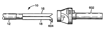
Referring now to Figures 28 through 30 of the
drawing, there is shown a preferred embodiment of
5 laparoscopic surgical instrument according to the
present invention which includes many of the same
elements of the devices discussed above which have been
identified by the same reference characters.
According to the present invention there is
10 provided a laparoscopic surgical instrument such as the
stapler 10 that is adapted to be inserted (or
"threaded") through a cannula 602 (Figure 28) and into
the abdominal cavity of a patient during a laparoscopic
surgical procedure.
The present invention comprises a
laparoscopic surgical -nstrument (e.g. the stapler 10)
which includes at least one mechanical tissue
engagement device (e.g. staples 518). While a stapler
10 is used as a particular example, as used in this
20 application, the phrase "laparoscopic surgical
instrument" should be construed broadly to include clip
appliers, tissue tackers and other surgical
instruments. Additionally, while staples 518 are used
as an example of a mechanical tissue engagement device,
25 as used in this application, the phrase "mechanical
tissue engagement device" should also be construed
broadly to include surgical clips, patches, tissue
tackers, and one-piece and two-piece staples.
The stapler 10 comprises a proximal portion,
30 a distal portion having staples 518, an actuation means
for placing the staples 518 on tissue, an elongate,
substantially cylindrical shaft portion or frame 12
between the proximal and distal portions for abutment
with inner surfaces of the cannula 602 when the stapler
35 10 is within the cannula 602, and a blocking body or
member 604.
-26-
O 094/24943 2 1 6 1 ~ ~ 8 PCT~S94/03192
Preferably, the actuation means includes
pusher rods 524 having distal ends 526 as discussed
above. The blocking body 604 is operatively associated
with the actuation means 524 as described below in
5 greater detail. The blocking body 604 is preferably
mounted to the cartridge 508 for pivotal movement
relative thereto between a non-blocking position
(Figure 29) which affords insertion and removal of the
distal portion of the stapler 10 through the cannula
10 602, and an insertion blocking position (Figures 28 and
30) in which the blocking body 604 affords removal of
the distal portion from the abdominal cavity, and in
which the blocking body 604 thereafter prevents
insertion of the distal portion through the cannula
15 602.
The stapler 10 also preferably includes a
biasing means such as a spring 605 for urging the
blocking body 604 toward the blocking position. A
ledge or shoulder surface 640 on the cartridge 508
20 functions as a stop surface to prevent further distal
movement of the body 604 relative to the cartridge 508
and to define the insertion blocking position of the
body 604. The spring 6~5 is illustrated as a torsion
spring which has a first portion attached to the
25 cartridge 508 and a second portion attached to a ledge
611 on the blocking body 604. However, it should be
noted that the biasing means may comprise any suitable
biasing means such as a coil spring, leaf spring or
even an inherently resilient blocking body 604 which
30 could press against the cartridge 508 to bias itself
toward the insertion blocking position.
Also preferably, the blocking body 604 is
pivotably mounted to the cartridge 508 by a pin 612 and
a groove in the cartridge 508. A flexible, resilient
35 latch 618 is also preferably present in the cartridge
508. The blocking body 604 has a pin 619 for engaging
-27-
W094/~943 ~ 65 PCT~S94/03192 -
the latch 618 to hold the blocking body 604 in the non-
blocking position, and a cam surface 629 for engaging
the distal end of the cannula 602 to afford removal of
the distal portion from the abdominal cavity through
5 the cannula 602 even when the blocking body 604 is in
the blocking position. The blocking body 604 also
includes an obstruction surface 631 for engaging the
cannula 602 to prevent the spent surgical instrument
from being reinserted through the cannula 602.
With the blocking body 604 in the non-
blocking position, the effective diameter of the distal
portion of the stapler 10 is approximately equal to or
less than the diameter of the internal surfaces of the
cannula 602 which allows the distal portion to be
15 inserted through the cannula 602. However, when the
blocking body 604 is in the insertion blocking position
(Figures 28 and 30), the effective diameter of the
distal portion of the stapler 10 is greater than the
diameter of the internal surfaces of the cannula 602,
20 and the stapler 10 is prevented from being reinserted
through the cannula 602.
It should be noted that when the blocking
body 604 is in the abdominal cavity and assumes the
insertion blocking position, it does not prevent the
25 stapler lO from being withdrawn from the cannula 602 as
the cam surface 629 will engage the end of the cannula
602 as the distal portion of the stapler 10 is being
withdrawn, and the cam surfaces 629 will cam the
blocking body 604 toward the non-blocking position
30 where it affords passage of the distal portion of the
stapler lO out of the cannula 602. Because the latch
618 is flexible and resilient, it will not unduly
hinder this return movement of the blocking body 604
toward the non-blocking position as it simply deflects
35 out of the path of pin 619.
-28-
21616~
094/24943 PCT~S94/03192
The materials used to construct the elements
of the cartridge 508 including the blocking body 604
and the spring 605 may comprise any suitable materials
- for use in surgical procedures. Polymeric and metal
5 materials may be utilized. Stainless steel is a
suitable material for the blocking body 604.
o~eration
The present invention will now be described
10 with reference to Figures 28 through 30. A surgeon
will first place a c~nnula 602 in the abdominal cavity
of a patient by using a trocar which is well known in
the art. Next, the distal portion of the stapler 10
will be inserted into the abdominal cavity through the
15 cannula 602. Typically the shaft 12 will abut the
internal surfaces of the cannula 602 so that
insufflation gas pressure will not be lost between the
cannula 602 and shaft 12.
The surgeon will then approximate (e.g.
20 place) the jaws of the stapler 10 on the tissue to be
stapled, and the actuation means will be actuated (the
stapler is fired). When the stapler is fired, the
pusher rods 524 move distally along a path within slits
528 as described above until the supply of staples 518
25 is depleted and the car'ridge is spent. As used in
this application, when it is said that a laparoscopic
surgical instrument is "spent" or that it is
"depleted", it is meant that there are no mechanical
tissue engagement devices (e.g. staples 518) remaining
30 to be engaged on tissue.
At a distal end portion of the path which the
pusher rod 524 follows, a distal end 526 of the pusher
rod 524 engages flexible latch 618 and moves the latch
from a latching position (Figure 29) to an unlatched
35 position (Figure 30) where the pin 619 is spaced from
the latch 618 so that the spring 605 may move the
-29-
;~ -
W094/24943 21 61 6~ PCT~S94/03192 ~
blocking body 604 to the insertion blocking position.
Thus, the distal end 526 of pusher rod 524 is
operatively associated with the latch 618. Preferabl~,
engagement between the distal end 526 of the pusher rod
5 and the latch 618 occurs during or just after the last
staple or staples are being formed in tissue.
If there is no obstacle (such as tissue)
obstructing the blocking body 604, the blocking body
may project beyond the periphery of the cartridge 508
10 and move to the blocking position even when it is
within the abdominal cavity. As stated above,
engagement between cam surfsce 629 and the end of the
cannula 602 as the stapler 10 is withdrawn from the
abdominal cavity moves the blocking body 602 back
15 toward the non-blocking position so that the stapler 10
may be withdrawn from the abdominal cavity.
Once the spent stapler 10 is removed from the
abdominal cavity, if a surgeon attempts to reuse the
stapler 10, engagement between blocking surface 631 and
20 a proximal surface on the cannula 602 will prevent the
stapler 10 from being reinserted into the abdominal
cavity through the cannula. The shape of the blocking
body 602 shown in Figure 30 as including first and
second portions situated at an included acute angle
25 presents a blocking body in the insertion blocking
position which is difficult to reset as the blocking
surface 631 is situated at a predetermined angle
relative to the cannula 602 such that it acts as a
camming surface to urge the stapler away from the
30 passage of the cannula 602 should the surgeon attempt
to force it through the cannula 602. Thus, the
blocking body 604 allows the spent surgical instrument
to be removed from the abdominal cavity through the
cannula, but thereafter prevents the instrument from
35 being reinserted through the cannula. Valuable time is
-30-
21 61 6S~
094/24943 PCT~S94/03192
not wasted by inserting a spent instrument through the
cannula, and tissue is not unnecessarily traumatized.
It will, of course, be understood that
modifications to the presently preferred ~ho~iment
5 will be apparent to those skilled in the art. For
example, the blocking body 604 need not comprise the V-
shape shown in Figures 29-30, and may comprise any
suitable shape so long as it performs the functions
described above.
-31-