Note: Descriptions are shown in the official language in which they were submitted.
~''~ 1247-7
2~ 6j 832
Forefoot relieving shoe, more particularly for
postoperative treatment
The present invention relates to a forefoot relieving shoe,
more particularly for postoperative treatment, with a sole
portion which is essentially triangular in a side view or
in a vertical longitudinal section and possessing a thick-
ness which diminishes toward the rear and which terminates
before the metatarsal region of the wearer.
BACKGROUND OF THE INVENTION
A forefoot relieving shoe of tnis type is known from the
US-A 4,546,557. Surgical interventions within the forefoot
region, especially in hallux valgus operations, call for
a postoperative period during which the forefoot Cwhich
cannot as yet be subjected to any strain) has to be trea-
ted with care. If the patient does not wish to walk with
the aid of crutches during this period, then the relie-
ving shoe mentioned in the beginning can provide a solu-
tion, whose obliquely disposed foot bedding, in connec-
tion with the sole portion terminating before the meta-
tarsal region, ensures that the patient is able to put
the weight on the foot and also to safely roll on the
same. The shoe according to said U.S. patent specifica-
tion has a compressible sole possessing a compressibility
which increases from the rear to the front. This design
is intended to serve for a better absorption of shocks
within the front area of the shoe. Apart from the circum-
stance that the adjustment of a differing degree of com-
pressibility in one sole portion is technically difficult
and/or costly, plastic sole portions, when in use, are
subjected to considerable mechanical stresses which, in
the event of material fatigue, may easily lead to Large
plastic portions breaking off, after which the sole por-
tion is unserviceable. A reinforcement of this sole
''~ 21 81832
- 2 -
portion which is possible in principle, is opposed by the
requirement for as low as possible a weight, just like the
requirements calling for the desired elasticity of the sole
portion when rolling the foot.
That is why the technical problem of the present invention
is to develop further the shoe to the effect that, without
damage being caused to the walking block, it makes longer
wearing periods or periods of use possible and ensures a
good wear comfort, particularly with respect to the desired
differing elasticity of the sole portion.
The technical problem is resolved by the forefoot relieving
shoe possessing the features described herein.
SUMMARY OF THE INVENTION
In one aspect, the invention provides a forefoot relieving
shoe for a foot having a metatarsal region and a calcaneal
tuberosity, the forefoot relieving shoe having a
longitudinal direction and a front and rear, the forefoot
relieving shoe comprising a single-piece sole portion having
an essentially triangular cross-section in the longitudinal
direction, the sole portion having an upper side, wherein a
thickness of the triangular sole portion decreases toward
the rear, and wherein the sole portion ends before the
metatarsal region, the sole portion comprising a homogeneous
foamed plastic body, a supporting carrier plate projecting
toward the front from the triangular sole portion, a leaf
spring embedded in the sole portion so as to be flush with
marginal areas of the upper side of the sole portion, the
leaf spring having a bottom side, further comprising a
curved spring having an anterior leg and a posterior leg,
and a front flat section connected to the anterior leg and a
rear flat section connected to the posterior leg, wherein
the front and rear flat sections of the curved spring are
attached to the bottom side of the leaf spring, the anterior
21 61832
- 2a -
leg extending essentially parallel to a sole portion front
face located adjacent the supporting carrier plate and
perpendicular to the upper side of the sole portion, and the
posterior leg extending at an angle of between 35° and 55°
relative to the upper side of the sole portion, wherein the
front flat section of the curved spring is located in a
transition area between the support carrier plate and the
triangular sole portion, and the rear flat section is
located a short distance in front of the calcaneal
tuberosity.
According to the invention, the sole portion is comprised of
a foamed plastic, in which a spring is embedded and which
can be tensioned against the pressure exerted on the shoe by
a foot. This spring thus brings about a permanently elastic
reinforcement, in which, by the adjustment of the spring
constants in each sole portion (segment), the desired
elastic recovery properties to differing extents are just as
realizable as with the aid of the spring, the synthetic
foamed material employed, which may be any plastic, improves
in a corresponding manner the durability of the sole
portion. It is possible to realize the invention with only
a single spring or with a group of springs which are
embedded in the foamed plastic independently of each other
or in an interconnected fashion.
By preference, the spring extends essentially over the
entire length of the sole (with the exception of marginal
areas).
2161832
- 3 -
According to a further construction of the invention, the
forefoot relieving shoe is provided with a sole portion
possessing a compressibility which increases from the rear
toward the front, which enhances the rolling comfort.
In a special embodiment of the invention, a leaf spring
is embedded on the top side of the sole which preferably
terminates flush with the marginal areas of the sole top
side. In this way a smooth bearing surface results which
is readily laid on and attached to the relief shoe bedding
sole and in which the spring is able to transmit its effect
close to the foot bedding sole. Contrary to the state of
the art, the differing elasticity is not ensured by the
homogeneous sole portion plastic member, but by the spring.
According to a further improvement, on the underside of
the leaf spring, the flat sections of a curved spring
bent aside at the end bear against said leaf spring or
they are connected to the same. The combination of a super-
jacent leaf spring with a curved spring permits an adapta-
tion of the spring configuration to the sole portion geo-
metry in the form of a reinforcement which is substanti-
ally extensible across the entire sole portion member.
As is known in principle according to the state of the
art, the one-piece sole portion possesses a supporting
carrier plate projecting over the, in the longitudinal
cross-section, triangular sole portion, on which the sole
portion front area extends in an S-configured manner as
far as to the bottom area of the sole portion. In this
case the leaf spring extends into the area of the sup-
porting carrier plate.
According to a further construction of the invention,
the curved spring possesses a first anterior leg which
extends, relative to the lower sole portion front area
2161832
- 4 -
following the supporting carrier plate, approximately pa-
rallel and/or vertical to the sole portion surface area.
The second leg of the curved spring extends preferably
relative to the sole portion surface at an acute angle
which, by preference, is between 35° and 55°. Between
the two legs, a substantially circular center piece is
located in such a way that, in cross-section, the curved
spring comes to possess the approximate configuration of
an obliquely disposed V-section with different inclina-
tions of the two legs. By preference, the front bent-aside
flat section of the curved spring, within the transitional
region from the supporting carrier plate to the triangular
sole portion and/or the rear bent-aside flat section,
shortly before the calcaneal tuberosity of the foot, is
disposed so as to bear against the Leaf spring.
In order to ensure that the spring is unable to become
displaced in the plastic member, the leaf spring and/or
the curved spring possess at least one perforation which
is reached through by the foamed plastic. In the flat sec-
tion springs, the perforations may be produced in the
form of drilled holes. Subsequent to the springs having
been aligned in an injection molding device, the sole
portion plastic material is cast into the injection mold,
if necessary, under pressure where, while including the
perforations, it flows through the free injection molding
cavities and, after curing, bears against the springs to
its full extent while penetrating the perforations and
is able to cure. By preference, the perforations are longi-
tudinally oval in cross-section. According to another
construction of the invention, the point before the contact
area with the curved spring presents itself as the loca-
tion for the perforation and, in the curved spring, the
posterior leg which is constructed so as to be longer
than the anterior leg.
21 61832
- 5 -
It is preferred that the spring is comprised of an
elastomeric plastic which possesses a greater hardness than
the foamed plastic of the sole portion.
In the drawings, an embodiment example of the invention is
depicted. Thus
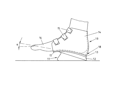
F i g. 1 shows a schematic side view of a forefoot relieving
shoe and
F i g. 2 shows a longitudinal cross-section through a sole
portion.
DETAIT.ED DESCRIPTION OF THE PREFERRED EMBODIMENT
The forefoot relieving shoe 10 is comprised of a sole por-
tion 11, possibly an intermediate portion or top member 12,
which may form part of the foot bedding 13, as well as of a
portion comprising two shells 14 connected to the top member
or the foot bedding which, by way of example, can be closed
by means of Velcro strip fasteners 15. The shells 19 may be
comprised of leather, plastic or textile fabric. The
forefoot relieving shoes is configured in such a way that
the forefoot 16 is exposed and raised in the direction of
the point of the foot, which is brought about by the
substantially triangular contour of the sole portion 11.
The angle of inclination ~ is regularly between 5° and 15°.
The foot bedding 13 terminates in the metatarsal region
which must not be subjected to any load. When walking, the
wearer of the forefoot relieving shoe 10 is able to first of
all put down the shoe in the region of the heel 18, to roll
on the foot in the forward direction without running the
risk of touching the ground with the forefoot or toes.
~. 21 618 3 2
- 6 -
As is shown by the longitudinal cross-sectional view of the
sole portion 11 in Fig. 2, the same is constructed in the
form of a one-piece homogeneous foamed plastic component in
which a spring is embedded and which is comprised of two
parts, viz. a leaf spring 20 and a curved spring 21. The
leaf spring 20, with the exception of a lateral marginal
area, extents to its full extent over the entire length and
width of the sole portion 11, more particularly it extends
as far as into the area of an anterior supporting carrier
plate 22 which projects above the triangular sole portion
which, incidentally, is followed by the front wall 23 in the
form of an S-shaped bend. The curved spring 21 is comprised
of an anterior leg, a curved base portion 25 and of a
posterior leg 26. At the end, bent-aside flat sections 27
and 28 follow the anterior and posterior legs, which bear to
their full extent against the underside of the leaf spring
20. The front flat section is located approximately in the
area of the extension of the front wall, that is to say
within the area of transition between the supporting carrier
plate 22 and the substantially triangular sole portion body
19.
The anterior leg is spacedly disposed approximately parallel
to the front face or front Wall 23 of the sole portion and
vertical to the leaf spring 20, whereas the rear leg 26 runs
out at an acute angle to the leaf spring 20. In addition,
the rear leg 26 is provided with a longitudinally oval
perforation 29, which is reached through by the foamed
material of the sole portion 19. The leaf spring 20 may be
provided with corresponding perforations, preferably within
the area of the front supporting carrier plate 22 and/or
within the rear area, i.e. behind the flat section 28 which
is bent aside at the end.
~1 61832
_ 7 _
The forefoot relieving shoe with the sole portion specified
in greater detail in Fig. 2 has, in comparison with the
embodiments known from the state of the art, been optimized.
A homogeneous rubber substance which is simple to prepare
from a production engineering viewpoint can be selected as
the material for the sole portion, which is strengthened by
the reinforcement with the aid of the spring 20,21 so that
this rubber substance will be able to withstand the walking
stresses over a longer period of time. By means of the
spring 20,21, a load distribution is achieved which
compensates the wearing compression of the foamed material
(rubber). Hereby it will not be possible from the very
outset for overloads to occur in the event of strong
compressions. The spring 20,21 is configured in such a way
that it covers the entire load surface area of the top side
and is equipped with a semicircular stiffening 24,25
reaching into the front rolling area. The bent-aside flat
sections 27 and 28 may be secured to the underside of the
leaf spring 20 by bonding. The double-layer spring 20,21
increases the forefoot flexibility and supports the rolling
motion in such a way that, in the direction toward the heel,
a further tread for absorbing the shocks is obtained. In
the rolling edge, by means of the springs 20,21, an
increased pressure is applied, whereby the forefoot is
relieved in a freely suspended manner.
As material, a plastic may be chosen which is mechanically
stable independently of temperature, i.e. which, in frost,
is just as resistant to fracture as under extreme heat
influences of up to 40°C. If necessary, the spring 20,21 is
pretreated with the aid of adhesion intensifiers in such a
way that it enters into an intensive intercrescence with the
foamed material 19. It is also possible for carbon fibers
to be employed as fabrication material for the spring 20,21.