Language selection

Search

Patent 2161860 Summary

Third-party information liability

Some of the information on this Web page has been provided by external sources. The Government of Canada is not responsible for the accuracy, reliability or currency of the information supplied by external sources. Users wishing to rely upon this information should consult directly with the source of the information. Content provided by external sources is not subject to official languages, privacy and accessibility requirements.

Claims and Abstract availability

Any discrepancies in the text and image of the Claims and Abstract are due to differing posting times. Text of the Claims and Abstract are posted:

  • At the time the application is open to public inspection;
  • At the time of issue of the patent (grant).
(12) Patent: (11) CA 2161860
(54) English Title: IMPROVED REGENERATIVE THERMAL OXIDIZER
(54) French Title: OXYDANT THERMIQUE A REGENERATION AMELIORE
Status: Expired
Bibliographic Data
(51) International Patent Classification (IPC):
  • F23G 7/06 (2006.01)
  • F23J 15/00 (2006.01)
(72) Inventors :
  • WILHELM, FRIEDRICH (Germany)
(73) Owners :
  • EISENMANN CORPORATION (United States of America)
(71) Applicants :
(74) Agent: FINLAYSON & SINGLEHURST
(74) Associate agent:
(45) Issued: 2000-01-18
(22) Filed Date: 1995-10-31
(41) Open to Public Inspection: 1996-06-28
Examination requested: 1995-12-12
Availability of licence: N/A
(25) Language of filing: English

Patent Cooperation Treaty (PCT): No

(30) Application Priority Data:
Application No. Country/Territory Date
364,768 United States of America 1994-12-27

Abstracts

English Abstract

A regenerative thermal oxidizer (RTO) is constructed to receive polluted waste gases from an industrial process, cleanse the gas and permit cleansed gas to exit the RTO to the environment. The RTO includes a lower section having an inlet to receive polluted or incoming gas, and a centrally positioned rotary distributor in the lower section for cooperation in controlling gas flow via a segmented center section. The rotary distributor is substantially smaller than the lower section and is of a substantially smaller cross section. Incoming gas is directed to a middle section segment(s), fills the segment(s) and then flows through a peripheral opening to a segmented upper section where it passes through a heat exchanger to a combustion chamber where it is oxidized or cleansed. From there cleansed gas passes through another upper section segment through a heat exchanger and back to center section segment(s). In the center section the cleansed gas flows to the rotary distributor where it is divided into outgoing and purge gases. The outgoing gas flows through the rotor to a manifold and then to an outlet. The purge gas flows through a purge segment in the rotor to a center discharge pipe. From the pipe the purge gas is directed to a conduit for exiting the RTO and the purge gas is then recycled to the incoming gas to the RTO.


French Abstract

Un oxydant thermique à régénération (OTR) est construit pour recevoir des gaz résiduaires pollués provenant d'un procédé industriel, purifier les gaz et permettre aux gaz purifiés pour quitter l'OTR vers l'environnement. L'OTR comporte une section inférieure ayant une entrée pour recevoir les gaz pollués ou entrants et un distributeur rotatif central dans la partie inférieure pour la coopération dans le contrôle des flux de gaz via une section centrale segmentée. Le distributeur rotatif est considérablement plus petit que la partie inférieure et d'une section transversale beaucoup plus petite. Les gaz entrants sont dirigés vers un ou plusieurs segments de la section centrale, remplissent ces segments et passent ensuite par une ouverture périphérique vers une section supérieure segmentée où ils traversent un échangeur de chaleur vers une chambre de combustion où ils sont oxydés ou nettoyés. De là, les gaz purifiés passent par un autre segment de section supérieure à travers un échangeur de chaleur et de retour vers un ou des segments de la section centrale. Dans la section centrale, les gaz purifiés s'écoulent vers le distributeur rotatif où ils se divisent en gaz sortants et en gaz de purge. Les gaz sortants traversent le rotor vers un collecteur, puis vers une sortie. Les gaz de purge traversent un segment de purge du rotor vers un tuyau d'évacuation central. Depuis le tuyau, les gaz de purge sont dirigés vers un conduit pour sortir de l'OTR et les gaz de purge sont alors recyclés dans le gaz entrant dans l'OTR.

Claims

Note: Claims are shown in the official language in which they were submitted.


The embodiments of the invention in which an exclusive property or
privilege is claimed are defined as follows:

1. A regenerative thermal oxidizer which includes:
an elongated housing which includes a lower section, a
center section and an upper section;
the lower section includes an incoming gas inlet, a
purge gas outlet and an outgoing gas outlet;
a rotary distributor centrally positioned in the lower
section and having portions for transmitting gas between the
lower section and the center section, for passing cleansed
outgoing gas from the central section to the outgoing gas outlet
and for defining a purge section;
the center section constructed and positioned between
the upper and lower sections to define a plurality of segments,
to receive incoming gas, to transmit incoming gas to a segmented
upper section and to receive cleansed gas from said upper
section and transmit cleansed gas to purge and outgoing gas
portions of the rotary distributor;
said upper section defining a plurality of segments
aligned with the center section segments and a combustion
chamber at the top thereof;
heat exchanger material positioned in each segment of
the upper section whereby pollutant-containing incoming gas can
pass through the heat exchanger material in a segment and
cleansed gas after burning in the combustion chamber can pass
through the heat exchanger material in a segment; and
said upper section being constructed to receive
polluted gas from the center section and discharge cleansed gas

10


to said center section.

2. A regenerative thermal oxidizer as in claim 1 wherein
said center section has a first partition or wall-like surface
that separates the center section and lower section and which
defines a centrally positioned opening which is substantially
smaller in cross section than the cross section of the housing
and adjacent said rotary distributor and a second partition
wall-like surface that separates the center section and the
upper section which defines a plurality of openings, each
opening associated with a segment and each opening positioned
adjacent the periphery of the housing whereby gas is caused to
flow in the center section, between the center opening and the
openings adjacent the periphery of the housing.

3. A regenerative thermal oxidizer as in claim 1 wherein
the rotary distributor includes a cylindrically-shaped body and
an apertured disc-shaped distribution plate mounted on the body,
which together control gas flow between the lower and center
sections.

4. A regenerative thermal oxidizer as in claim 3 wherein
said body defines an angular surface for deflecting incoming gas
from the lower section toward the center opening and to the
center section and said distribution plate includes an aperture
aligned with the angular surface through which incoming polluted
gas passes as it moves to the center section from the lower
section.

5. A regenerative thermal oxidizer as in claim 3 wherein

11


said body defines an open top and an open bottom chamber for
directing cleansed outgoing gas from the center section to the
outgoing gas outlet in the lower section and said distribution
plate includes an outgoing gas aperture aligned with the
outgoing gas chamber through which cleansed outgoing gas is
passed from the center section to the lower section and the
outgoing gas outlet.
6. A regenerative thermal oxidizer as in claim 5 wherein
there is provided a manifold connected to the open bottom
chamber and the outgoing gas outlet.
7. A regenerative thermal oxidizer as in claim 5 wherein
said body defines a purge gas chamber, having an open top, a
closed bottom and center conduit, whereby gas from the center
section flows through said open top and exits the purge chamber
through the center conduit to a purge gas conduit outlet and
said distribution plate includes a purge gas aperture aligned
with the purge gas chamber through which purge gas passes from
the center section to the lower section.
8. A regenerative thermal oxidizer as in claim 1 wherein
a wall separates the center and upper sections and a plurality
of openings in said wall are aligned with and provide
communication between center section segments and upper section
segments.
9. A regenerative thermal oxidizer which includes:
an elongated housing which includes a lower section, a
center section and an upper section;


12


the lower section includes an incoming gas inlet, a
purge gas outlet and an outgoing gas outlet;
a rotary distributor centrally positioned in the lower
section having portions for transmitting incoming gas between
the lower section and the center section, for passing outgoing
cleansed gas from the center section to the lower section and
for defining a purge section;
said center section having a periphery and constructed
and positioned between the upper and lower sections to define a
plurality of segments to receive incoming gas, to transmit
incoming gas to a segmented upper section, to receive cleansed
gas from the upper section and to transmit cleansed gas to the
purge and outgoing gas portions of the rotary distributor;
said upper section defining a plurality of segments
aligned with the middle section segments and a combustion
chamber at the top thereof;
heat exchanger material position in each segment
whereby pollutant-containing gas can pass through the heat
exchanger material in each segment and cleansed gas after
burning in the combustion chamber can pass through the heat
exchanger material in each segment;
said upper section having a periphery and constructed
to receive polluted gas from the center section and discharge
cleansed gas to the center section;
said center section having a first partition or wall-like
surface that separates the center section and lower section
which defines a centrally positioned opening which is
substantially smaller than the cross section of the housing and


13


a second partition or wall-like surface that separates the
center section and the upper section which defines a plurality
of openings, each opening associated with a segment and each
opening positioned adjacent the periphery of the housing whereby
gas is caused to flow in the center section between the center
opening and the openings adjacent the periphery of the center
section;
the rotary distributor includes a cylindrically-shaped
body and a disc-shaped, apertured, distribution plate having a
center axis, which body and plate together control gas flow
between the lower and center sections;
said body defines an angular surface for deflecting
incoming gas from the lower section toward the center section
and said distribution plate includes an incoming gas aperture
aligned with the angular surface through which the incoming
polluted gas passes as it moves to the center section from the
lower section; and
said body defines an open top and an open bottom
chamber for directing outgoing cleansed gas from the center
section to the outgoing gas outlet in the lower section, said
distribution plate including an outgoing gas aperture aligned
with the outgoing gas chamber through which outgoing cleansed
gas is passed from the center section to the lower section and
the outlet;
there is provided a manifold connected to the open
bottom chamber and the outgoing gas outlet;
said body defines a purge gas chamber, having an open
top, a closed bottom and a center conduit whereby gas from the


14


center section flows through said open top and exits the purge
chamber through the center conduit to a purge gas conduit
outlet, said distribution plate including a purge gas aperture
aligned with the purge gas chamber through which purge gas
passes from the center section to the lower section, said
incoming gas aperture in said distribution plate being
positioned on one side of the center, the outgoing aperture in
said distribution plate being positioned on the other side of
the center and the purge gas aperture in the distribution plate
being positioned between the incoming gas aperture and outgoing
gas aperture, said distribution plate being adapted to rotate in
a direction whereby the plate is associated with the incoming
gas aperture before the purge gas aperture and with the purge
gas aperture before the outgoing gas aperture; and
the three apertures are located approximately the same
radial distance from the center of the distribution plate.
10. A method for cleansing polluted industrial gases,
comprising the steps of:
providing a regenerative thermal oxidizer (RTO) unit
including an elongated housing with lower, center and upper
sections, each section having a peripheral wall and the lower
section having an incoming polluted gas inlet, an outgoing
cleansed gas outlet, a purge gas outlet and a rotary distributor
for coordinating inlet gas flow between the lower section and
center section and for coordinating purge gas flow and outlet
gas flow from the center section to the lower section, said
center section defining a plurality of gas receiving segments, a
first wall-like partition separating the lower and center


15


sections and having a central aperture having an axis which
aperture cooperates with the rotary distributor in the passage
of gas between the lower section and center section and a second
wall-like partition separating the center and the upper sections
and having a plurality of openings, one opening being associated
with each segment and each opening being positioned radially
outwardly of the axis of said central aperture and inwardly of
the peripheral wall of said center section;
causing incoming polluted gases to flow into the lower
section of the RTO unit;
passing the incoming gas from the lower section to
selected segments of the center section through the center
aperture in the wall-like partition between the center section
and lower section;
causing the polluted gas to flow from the center of
the center section toward the periphery thereof;
causing the polluted gas to pass upwardly through an
opening in the wall-like partition between the center section
and upper section and into the upper section segments;
flowing the polluted gas through heat exchanger
material in an upper section segment to a combustion chamber for
oxidation and cleansing;
flowing cleansed gas downwardly through selected
segments of the upper section to the opening in the wall-like
partition between the upper section and center section;
flowing cleansed gas from the periphery of the center
section to the central aperture of the center section;
separating the cleansed gas into a purge gas portion


16


and an outgoing gas portion in the lower section;
flowing the outgoing cleansed gas through the lower
section to an outlet; and
flowing the purge gas through the lower section to a
purge gas outlet.
11. A regenerative thermal oxidizer for receiving
pollutant-containing incoming gas, treating said incoming gas
and discharging treated gas, said oxidizer including:
an elongated housing defining a lower section, a
center section and an upper section;
the lower section defining an incoming gas inlet, an
outgoing gas outlet, a purge gas outlet and a plenum for
receiving incoming gas from said incoming gas inlet;
the center section being adjacent the lower section
and the upper section (a) for receiving incoming gas from the
lower section and directing said gas to the upper section and
(b) for receiving treated gas from the upper section and
directing treated gas to the lower section;
the upper section including a lower portion having
therein heat exchanger material and an upper portion defining a
combustion chamber, said upper section constructed for receiving
incoming gas from the center section and directing said incoming
gas through the heat exchanger material to the combustion
chamber, treating the incoming gas in the combustion chamber and
directing treated gas from the combustion chamber through heat
exchange material to the center section; and
a rotary distributor having a substantially central
axis of rotation and positioned in the lower section and within


17


the plenum and constructed to receive incoming gas from the
incoming gas inlet and distribute incoming gas to the center
section, to receive treated gas from the center section and
transmit treated gas to the outgoing gas outlet and to the purge
gas outlet.


18

Description

Note: Descriptions are shown in the official language in which they were submitted.


2161860
IMPROVED REGENERATIVE THERMAL OXIDIZER
BACKGROUND OF THE INVENTION
This invention relates to an apparatus for efficiently
cleaning polluted waste gases from an industrial process and more
particularly to an apparatus known as a regenerative thermal
oxidizer (hereinafter an RTO).
It is desirable to clean polluted gases which exit an
industrial process so as to emit or release clean gases to the
environment.
There are many devices which provide clean gases. See
for example, U.S. Patents 3,172,251; 3,914,088; 3,997,294;
4,280,416; 4,454,826; 4,650,414; 4,678,643; 4,850,862; 4,867,949;
5,016,547; 5,024,817; 5,163,829 and German Patent 133,704. See
also European patent document No. 0548 630 A1, which discloses a
regenerative thermal oxidizer.
Incineration systems may employ a combustion chamber to
burn or incinerate incoming polluted gases and related delivery
and valuing mechanisms. There is an inlet to receive incoming
polluted gas and a structure or mechanism to direct the incoming
gas to a combustion chamber. In some systems the incoming gas
passes through heat exchanger material (which has been heated)
before it reaches the combustion chamber to raise the incoming gas
temperature. In the combustion chamber the gas is burned or
cleaned and the cleansed or outgoing gas is directed, sometimes,
through heat exchanger material, where it gives up heat and then
to an outlet for outgoing cleaned gas. The heat exchanger
materials are used to transfer heat from the outgoing gas to the
incoming gas.
1


2161860
It has been found to be desirable to segment the
combustion chamber construction and sequentially pass incoming gas
to selected segments and receive outgoing gas from other,
generally oppositely positioned, selected segments. This is
sometimes done using a distribution device which may be rotary.
It has also been found to be desirable to purge a
segment before cleaned or outgoing gas passes through that
segment. The purge gas is usually from external sources. Rotary
valuing for the sequential delivery of incoming and purge gases
and expulsion of outgoing gas is shown. Also see for example U.S.
Patents 4,280,416 and 5,016,547.
European Patent document 0548 630 A1 discloses an RTO
device where the purge gas is drawn from the cleaned outgoing gas
and exits an upper section via a rotating segment that is as large
in radius as the RTO housing.
It is believed that the European unit embodies many
desirable features and while generally acceptable can be improved
in efficiency and for use in the United States of America.
Therefore, it is an object of this invention to provide
improvements to a European type system so as to render it more
efficient and more acceptable in the U.S.
This and other objects of this invention shall become
apparent from the following description and appended claims.
SUMMARY OF THE INVENTION
There is provided by this invention an improved RTO
which has an elongated housing and has lower, center and upper
sections and a smaller diameter rotating segment, which also known
2


2161860
as a rotary distributor, that cooperates with the center section.
Incoming polluted gas enters the unit via an inlet in the lower
section, flows to and through the center section, to the upper
section, through a heat exchanger and to the combustion chamber.
The polluted gas is burned and cleansed in the combustion chamber
and flows downwardly through heat exchanger material to and through
the center section and then to the rotary distributor where it is
divided into purge and cleaned gas . The cleansed gas f lows through
the distributor and exits via an outlet. The purge gas enters a
chamber in the distributor, flows to the center of the distributor
and exits via a purge gas outlet where it may be recycled into the
incoming polluted gas.
The rotary distributor is located at the center of the
lower section, cooperates with the center section, and is
significantly smaller than the diameter of the lower or center
sections. Incoming gas passes between the lower section and the
center section adjacent the center thereof. On the other hand gas
passes between the center and upper sections outwardly of the
center, adjacent the periphery, so that the center section becomes
a distributor chamber.
This unit is improved and believed to be more efficient
than prior art units and is believed to be more in line with U.S.
practices.
BRIEF DESCRIPTION OF DRAWINGS
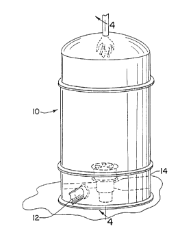
Figure 1 is a perspective view of the exterior of a
Regenerative Thermal Oxidizer (RTO) showing parts of the lower
section in phantom or by broken line;
3


~1~18G0
Figure 2 is a perspective view of the lower section of
the RTO with the inlet, outlet and rotary distributor shown;
Figure 3 is an exploded perspective view of the rotary
distributor shown in Figure 2;
Figure 4 is a vertical cross-sectional view taken along
line 4-4 of Figure 1 showing the interior of the RTO and depicting
the gas flow path;
Figure 5 is a horizontal cross-sectional view taken along
line 5-5 of Figure 4 and showing the center section; and
Figure 6 is a horizontal cross-sectional view, similar
to Figure 5, taken along line 6-6 of Figure 4 and showing the lower
section with the inlet, outlet, purge conduit and distributor.
DESCRIPTION OF THE PREFERRED EMBODIMENT
Referring f first to Figure 1, there is shown a RTO 10 that
is generally vertical, cylindrical and elongated and has an inlet
12 for polluted or incoming gas and an outlet 14 for cleansed or
outgoing gas. A combustion chamber is provided at the top of the
RTO and is suggested by the flame 16.
Referring now to Figure 4 and 6, incoming gas enters the
RTO via inlet 12 and flows into a plenum or space 18 defined by the
lower section. The incoming gas fills the plenum and flows to a
centrally-positioned rotary distributor 20 generally and is
deflected by the angular plate 22 to the center section 26. A
wall-like partition or plate 25 separates the lower and center
sections and there is provided a central opening 24 in the plate.
The center section is somewhat disc-like, cylindrical, stationary
and defines eleven (11) pieshaped segments. Incoming gas enters
4


2161860
a segment or segments of the center section at the center and fills
the segment. The gas flows toward the periphery to a peripheral
opening such as 28 in the upper plate 29. An opening such as 28
is provided for each segment and leads to the upper section 30.
The upper section 30 is also segmented into 11 pie-shaped
segments which are aligned with the center section segments and the
peripheral opening such as 28. Each segment in the upper section
has a small space 34 adjacent the opening such as 28. A perforated
metal plate 36 that supports heat exchange material also defines
the top of the space. Each upper section segment is filled with
heat exchange material, such as ceramic granules 38. The
perforated plate 36 acts as a support for the ceramic. The
incoming gas flows through the heat exchange material or granules
38 to the combustion chamber 16 where the pollutants are oxidized.
The heat exchange material has been previously heated and thus the
incoming gas picks up heat.
The incoming polluted and heated gas is then burned,
oxidized and forms outgoing or cleansed gas which passes through
the other segment 40 and the heat exchange material 42. The
segments) for the incoming gas may be diametrically opposite the
segments) for the outgoing gas. The cleansed gas exits the upper
section via an opening such as 28 and enters the center section via
peripheral opening 31. As it exits the upper section, the outgoing
gas loses heat to the heat exchange material.
As will be recalled, the center section is segmented, the
outgoing gas fills the segment, passes to the center and then down
through the center opening 24 and to the rotary distributor 20.
From the distributor, the cleansed gas passes to the exit 14.
S


2161860
A small portion of the cleansed gas is separated from the
outgoing gas and becomes purge gas. The purge gas is directed to
the center of the rotary distributor and then outwardly through the
purge gas conduit 44.
The Rotary Distributor
In considering the rotary distributor 20, reference is
made to Figures 2, 3, 4 and 6. The rotary distributor 20 is a
cylindrical member which is adapted to rotate about a central axis .
Its outside diameter is significantly less than the housing
diameter or the distance from the center to the periphery of the
housing. Rotation in this embodiment is in a counter-clockwise
direction. A motor drive and transmission shaft arrangement 46
generally located on the outside of the housing drives or rotates
the distributor.
The rotor is positioned between a stationary manifold 48
in the lower section and a stationary segmented grate-like member
50 that is mounted at the center of plate 25 that forms the lower
section/middle section interface.
The rotor itself is made up of a cylindrically shaped
body 54 and a circular or disc-like distribution plate 56 that is
secured to the top of the body by elongated screw-like members such
as 58 and 60. The rotary distributor transmits, provides
communication and distributes gas between the lower section and
segments of the center section. The body 54 includes a formed and
partially cylindrical housing part 50 that defines the angle or
deflection plate 22, a purge gas receiving segment 64 and a large
arc-shaped outgoing gas section 66. It is noted that the outgoing
6


2161860
gas section is open at the top to receive outgoing gas and is open
at the bottom to permit the outgoing gas to flow through the rotor
into the manifold 48. The purge gas section is pie-shaped, has a
bottom plate 68 which closes the bottom and an open center pipe 70
that communicates with the segment 64 and a conduit 72 in the
manifold 48.
From Figure 4 it is seen that the outgoing gas fills the
body interior, and passes through the body to the manifold 48 and
from there to the exit 14. From Figures 2 and 6, it is seen that
the purge gas flows into the segment 64, fills the segment, flows
to the center pipe 70 and through the center pipe to the purge
conduit 44 . Incoming gas enters the inlet 12 , f ills the lower
isection 18, surrounds the rotary distributor 20 and is deflected
by plate 22 through the grate 50 to the center section.
The distributor plate 56 includes an elongated arc-shaped
incoming gas aperture 74, a small pie-shaped purge gas segment
aperture 76, and a large arc-shaped outgoing gas aperture 78. It
is to be noted that the incoming aperture 74 is generally opposite
the outgoing gas aperture 78. Moreover, the incoming aperture is
smaller than the outgoing aperture 78. The purge aperture 76 is
positioned between the incoming gas aperture 74 and outgoing gas
aperture 78 and is smaller than the other apertures.
The distributor plate is mounted to the rotor body 54 in
a particular orientation. The incoming gas aperture 74 is aligned
with the deflection plate 22 so gas does not flow through the
rotary distributor but is deflected off plate 22. The purge
aperture 76 is aligned with the purge segment 64. The outgoing gas
aperture 78 is aligned with the remainder of the rotor and not the
7


2161$60
purge aperture 64 or deflection plate 22.
The grate 50 fits in the plate 25 at the center 26, and
the plate divides the lower section and middle section. The grate
defines the openings through which incoming gas enters the center
section and outgoing gas and purge gas exits the center section.
The grate is segmented and the grate segments are aligned with the
section segments.
Operation
In operation, incoming gas fills the lower section 18 and
is deflected by plate 22 through the grate to the center section.
The incoming gas fills center section segments and flows to the
upper section and the combustion chamber. At the combustion
chamber the polluted gas is cleansed to form outgoing gas and from
the combustion chamber, outgoing or cleansed gas flows through the
upper section segments, to the center section segments and to the
center grate 50. Outgoing gas flows through the grate 50, a small
portion of the gas flows to the purge aperture 76 and the rest to
the outgoing gas aperture 78. The outgoing gas fills the body 54,
flows through the body bottom, to the manifold 48 and then flows
to the exit 14 via conduit 80.
Some cleansed gas enters the purge aperture 76 , f lows
into the purge segment 64 and to the center pipe 70. At the pipe,
the gas flows downwardly to the conduit 72 and out through the
purge conduit 44. It will be noted that the purge gas cannot flow
upwardly in the center pipe as the top of the pipe is closed off
by a plug-like construction 82.
8


z ~ 6 ~ s6o
As the distributor is rotated, the incoming, purge and
outgoing gas flow to and from different center section segments.
The incoming gas is heated by the heat exchange granules
which have been heated by the outgoing gas when it passed
downwardly through an upper section segment which is now used for
incoming gas. Thus, the outgoing gas looses heat to the heat
exchange granules as it passes from the combustion chamber to the
center section and incoming gas picks up heat.
In this embodiment, the distributor is rotating counter
clockwise and thus the purge aperture 76 leads the outgoing gas
aperture 78 so that the purge segment captures the beginning
portion of the outgoing gas and thus minimizes the contaminant
content of the outgoing gas that exits the system. The purge gas
is normally directed back to the incoming gas and is in a sense
recycled through the system.
Numerous changes and modifications can be made to the
embodiment disclosed herein without departing from the spirit and
scope of the invention.
9

Representative Drawing
A single figure which represents the drawing illustrating the invention.
Administrative Status

For a clearer understanding of the status of the application/patent presented on this page, the site Disclaimer , as well as the definitions for Patent , Administrative Status , Maintenance Fee  and Payment History  should be consulted.

Administrative Status

Title Date
Forecasted Issue Date 2000-01-18
(22) Filed 1995-10-31
Examination Requested 1995-12-12
(41) Open to Public Inspection 1996-06-28
(45) Issued 2000-01-18
Expired 2015-11-02

Abandonment History

There is no abandonment history.

Payment History

Fee Type Anniversary Year Due Date Amount Paid Paid Date
Application Fee $0.00 1995-10-31
Registration of a document - section 124 $0.00 1996-05-30
Maintenance Fee - Application - New Act 2 1997-10-31 $100.00 1997-10-21
Maintenance Fee - Application - New Act 3 1998-11-02 $100.00 1998-10-22
Maintenance Fee - Application - New Act 4 1999-11-01 $100.00 1999-10-13
Final Fee $300.00 1999-10-18
Maintenance Fee - Patent - New Act 5 2000-10-31 $150.00 2000-10-18
Maintenance Fee - Patent - New Act 6 2001-10-31 $150.00 2001-10-22
Maintenance Fee - Patent - New Act 7 2002-10-31 $150.00 2002-10-18
Maintenance Fee - Patent - New Act 8 2003-10-31 $150.00 2003-10-02
Maintenance Fee - Patent - New Act 9 2004-11-01 $200.00 2004-10-04
Maintenance Fee - Patent - New Act 10 2005-10-31 $250.00 2005-10-04
Maintenance Fee - Patent - New Act 11 2006-10-31 $250.00 2006-10-02
Maintenance Fee - Patent - New Act 12 2007-10-31 $250.00 2007-10-01
Maintenance Fee - Patent - New Act 13 2008-10-31 $450.00 2008-11-17
Maintenance Fee - Patent - New Act 14 2009-11-02 $250.00 2009-10-20
Maintenance Fee - Patent - New Act 15 2010-11-01 $450.00 2010-11-01
Maintenance Fee - Patent - New Act 16 2011-10-31 $450.00 2011-10-28
Maintenance Fee - Patent - New Act 17 2012-10-31 $450.00 2012-09-27
Maintenance Fee - Patent - New Act 18 2013-10-31 $450.00 2013-09-20
Maintenance Fee - Patent - New Act 19 2014-10-31 $450.00 2014-09-22
Owners on Record

Note: Records showing the ownership history in alphabetical order.

Current Owners on Record
EISENMANN CORPORATION
Past Owners on Record
WILHELM, FRIEDRICH
Past Owners that do not appear in the "Owners on Record" listing will appear in other documentation within the application.
Documents

To view selected files, please enter reCAPTCHA code :


To view images, click a link in the Document Description column. To download the documents, select one or more checkboxes in the first column and then click the "Download Selected in PDF format (Zip Archive)" or the "Download Selected as Single PDF" button.

List of published and non-published patent-specific documents on the CPD .

If you have any difficulty accessing content, you can call the Client Service Centre at 1-866-997-1936 or send them an e-mail at CIPO Client Service Centre.


Document
Description 
Date
(yyyy-mm-dd) 
Number of pages   Size of Image (KB) 
Cover Page 1996-03-19 1 15
Abstract 1996-03-19 1 44
Description 1996-03-19 9 386
Cover Page 2000-01-12 1 46
Drawings 1996-03-19 3 166
Claims 1996-03-19 7 284
Description 1999-03-31 9 357
Claims 1999-03-31 9 324
Representative Drawing 2000-01-12 1 8
Correspondence 1999-10-18 1 31
Correspondence 1996-05-30 1 25
Correspondence 1996-07-19 1 57
Correspondence 1995-12-05 1 30
Correspondence 1996-01-12 1 34
Correspondence 1995-10-31 1 26
Correspondence 1995-12-12 1 35
Prosecution-Amendment 1998-11-19 6 201
Prosecution-Amendment 1998-05-19 2 70
Prosecution-Amendment 1998-02-03 5 141
Prosecution-Amendment 1997-08-05 3 123
Assignment 1995-10-31 3 106
Assignment 1996-03-25 3 190
Prosecution-Amendment 1996-03-25 1 28