Note: Descriptions are shown in the official language in which they were submitted.
WO 94/27088 ~ PCTIGB94I00969
-1-
BURNER SYSTEM
TECHNICAL FIELD
This invention relates to a gas burner system for use in heating
apparatus.
BACKGROUND ART
Ovens of the kind having a conveyor running beneath overhead
transverse gas burners are widely used for continuous production of bread,
pies, pizzas, biscuits and other baked foodstuffs.
The gas burners comprise tubes with side slots. Gas fed from one
end burns, as a ribbon flame, along the side slots. In the case where a
uniform flame is used along the length of the tube it is difficult to attain
uniformity of heating since the edges of the conveyor tend to have different
thermal transfer characteristics compared with the central region, typically
giving greater heating at the edges.
Lack of uniformity is disadvantageous because this means that
foodstuffs will not be equally baked across the conveyor. In an attempt to
overcome this problem it is known to use a burner tube with two edge slots
and one central slot all of equal length and communicating with separate
internal compartments fed with gas via respective feed pipes and control
valves. In this way it is possible to produce different flame sizes, and hence
different heat intensities, at the edges compared with the central region.
However, this does not provide a total solution to the problem because the
change in thermal transfer characteristics across the conveyor will not
WO 94!27088 ,: PCT/GB94/00969 '
~.~6'.~~99
_2_
normally occur in three distinct regions corresponding to the positioning of
the three burner tube slots.
A further problem arises in connection with the attainment of high
thermal output along the length of the three-compartment gas burner. The
three compartments are fed with air and gas mixed with a Venturi injector.
The ratio of the air to gas, and the flow rate of the mixture determine the
thermal output per unit length of the gas burner slots. In the context of the
short length slots of the three compartments, an inconvenient limitation may
be imposed on the maximum flow rate and hence the maximum thermal
output due to destabilisation of the flame. As the flow rate is increased by
increasing mixture pressure and/or reducing slot width, there is an increasing
tendency for the flame to 'blow away' or otherwise destabilise. By way of
example, whereas a 90,000 BTU/hr (95,000 KJoules/hr output may be
attainable with a single zone 39 inch (99cm) burner, it may be necessary to
turn down the flow rate with a three-compartment burner of the same overall
length so that a maximum output of only 45,000 BTU/hr (47,500 KJ/hr) is
attainable.
Three-compartment burners may require complex and costly control
systems for switching off the flames e.g. during gaps and product change-
overs.
DISCLOSURE OF THE INVENTION
One object of the present invention is to provide a gas burner system
for use in heating apparatus whereby a desired distribution of heating
WO 94/27088 ~ 1 fi 18 9 9 PCTIGB94/00969
-3-
intensity can be more readily achieved along a heating region.
According to one aspect of the invention therefore there is provided
a gas burner system for use in heating apparatus along a heating region, said
system comprising a tube extending along said region, a plurality of outlet
apertures for burning gas extending along said tube, said tube being
separated into a plurality of compartments communicating respectively with
the apertures, and feed conduits for connecting said compartments to a
source of combustible gas, characterised in that the apertures comprise two
edge region apertures respectively at the end portions of the tube, and one
or more central region apertures in the central portion of the tube between
said end portions, the length of each edge region aperture being a minor
proportion of the length of the central portion. Preferably there are a
plurality of central region apertures.
With this arrangement, it is possible more readily to attain a desired
distribution of heating intensity along the heating region to match changes
in thermal transfer characteristics.
Preferably combustion is independently adjustable, particulariy by
adjustment of flow rate and/or mixing of gas and air, for each said
compartment. Thus, there may be a respective mixer and also respective
control valves for controlling supply and mixing of gas and air for each said
compartment. Each mixer may be a Venturi injector of known kind and for
each compartment there may be separate gas and air valves of a screw kind
or any other suitable kind, such valves being physically integrated with or
WO 94/27088 PCT/GB94I00969
~1G1~99
-4-
separate from the mixer.
Preferably also, the length of at least some of the outlet apertures
(and preferably all) is adjustable. Thus, the tube may be separated into said
compartments by means of barriers, said barriers being movable along the
tube in relation to a continuous aperture slot so as to shorten or lengthen
the
compartments and hence the lengths of the aperture slot in communication
therewith.
Preferably the burner tube has a continuous aperture slot (or
equivalent as mentioned below) along one side, and a plurality of barrier
walls are mounted within the tube on an elongate supporting member so as
to be positionally adjustable along the tube. In one embodiment the elongate
supporting member comprises an inner tube and the barriers comprise collars
between the outer surface of the inner tube and the inner surface of the
outer tube.
The tube may also be of circular cross-section, except for the outlet
aperture slot which preferably is bounded by outwardly projecting side walls.
The feed conduits may be connected to said compartments via
chambers in the inner tube.
Supply of combustible gas to the compartments may also be achieved
via feed apertures provided in the tube at positions which are spaced
longitudinally along the tube.
In this case an elongate feed block or chamber may run along the
tube, e.g. along the opposite side of the tube to the continuous outlet slot
WO 94/27088 ~ ~ 6 ~ g ~ g PCT/GB94/00969
_5_
. therein, said feed conduits comprising bores or pipes which run through the
block or chamber and connect at one end with the feed apertures and at the
other end with gas/air mixers and/or control valves e.g. in a manifold
structure on the end of the block or chamber.
Alternatively, the burner tube may have an internal pipe with an
outlet, such as a continuous slot, therealong, aligned with the outlet slot in
the tube, and with feed apertures spaced along and also circumferentially
around the pipe with which the feed conduits connect.
In this case, the feed conduits may comprise channels running along
the inner surface of the burner tube and which are aligned respectively with
the feed apertures in the inner pipe. These channels may connect with
gas/air mixers and/or control valves e.g. in a manifold structure at one end
of the outer burner tube.
In a particularly preferred arrangement there are three central region
burner apertures between the two edge region apertures. The edge region
apertures may be much shorter than the central region apertures e.g. each
edge region aperture constituting a minor proportion of the length of a
central region aperture and preferably constituting about 10% to 12/2% of
the overall length of the burner apertures. Preferably also the burner tube
length is greater than the length of the heating region.
With regard to the above mentioned continuous burner tube slot, this
constitutes a continuous slot in the sense that it acts to produce in use a
continuous ribbon flame along the slot. Thus, the continuous slot may be
WO 94/27088 PCT/GB94/00969
2~~I8~9
-6-
defined by a continuously free elongate opening, or alternatively by multiple
closely positioned openings. In a preferred embodiment the continuous slot
is a stepped slot having inner and outer portions, the outer portion being
wider than the inner portion.
In a particularly preferred embodiment the slot contains a flow
dispersing structure. In this respect it is known to provide a simple flow
dispersing structure in a burner tube slot comprising an inserted strip bent
from side to side in wave formation to define a series of holes between the
strip and the side walls of the slot. However, the holes are relatively large
and this limits the degree of flow dispersion. Flow dispersion facilitates
power output in that it enables a stable flame to be maintained at higher
rates of gas flow, and hence permits higher levels of power output. Without
flow dispersion, the flame will tend to blow off as the flow rate is
increased.
Most preferably, the flow dispersing structure comprises two or more
side by side strips bent from side to side to define a series of gas flow
holes
therebetween.
With this arrangement, a relatively high degree of flow dispersion can
be readily attained.
The strips may be bent sinuously with the wave formations of
adjoining strips out of phase. Other arrangements involving in-phase sinuous
strips, and/or other shapes of strips or interposed straight strips or the
like
can also be used.
The gas burner system of the invention may be used in heating
WO 94/27088 PCT/GB94/00969
2161Rq9
_,_
equipment of the kind having a conveyor band running between transverse
gas burners located above and/or below the band.
According to a second aspect of the present invention there is
provided a gas burner system for use in heating apparatus along a heating
region, said system comprising a tube extending along said region, a plurality
of outlet apertures for burning gas extending along said tube, said tube being
separated into a plurality of compartments communicating respectively with
the apertures, and feed conduits for connecting said compartments to a
source of combustible gas, characterised in that the apertures comprise two
edge region apertures respectively at the end portions of the tube, and one
or more central region apertures in the central portion of the tube between
said end portions, flow of said combustible gas through each said aperture
being independently adjustable.
BRIEF DESCRIPTION OF THE DRAWINGS
The invention will now be described further by way of example only
and with reference to the accompanying drawings in which:-
Fig. 1 is a schematic perspective view of an oven incorporating
one form of a burner system according to the invention;
Fig. 2 is a diagrammatic longitudinal sectional view of the
burner system;
Fig. 3 is a transverse sectional view on the line 3-3 of Fig. 2,
to a larger scale;
Fig. 4 is an end view from the right of Fig. 2;
WO 94/27088 ~ v PCT/GB94/00969
'x161899
_8_
Figs. 5 & 6 are diagrammatic plan views of alternative flow
distributing structure; and
Figs. 7 & 8 are views corresponding to Fig. 3 of alternative
embodiments of the burner system.
Fig. 9 is a view corresponding to Fig. 3 of a yet further
embodiment.
DESCRIPTION OF THE PREFERRED EMBODIMENTS
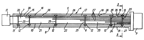
Referring to Figures 1-4, an oven has a conveyor 1 running
horizontally through a tunnel 2 having a series of overhead gas burners 3
extending transversely across the conveyor 1.
Each burner 3 consists of a burner tube 4 which is a cast or extruded
section comprising an elongate tubular body part 5 of essentially circular
cross-section with a radially outwardly projecting ridge 6 extending the
entire length of the body part parallel to its axis. The section has a central
circular bore 7 and a stepped slot 8 is milled through the ridge 6 to meet the
bore 7.
At one end the body part 5 is flanged and attached to a distributor
body 9 yet to be described. There is a circular cross-section inner tube 10
extending axially along the bore 7. This tube 10 is spaced from the inner
surface of the bore 7. At one end it is fixed to the distributor body 9. At
the other end it projects beyond the end of the outer tube 4 and is fixed to
a mounting member 11. The inner tube 10 has mounted thereon six collars
12 each of which fits in close contact with the outer surface of the inner
- WO 94/27088 ~ 161 ~ 9 9 PCTIGB94100969
_g_
tube 10 and the inner surface of the bore 7 and which has a radially
projecting flange 13 which fits in close contact with the inner surface of the
inner portion 14 of the stepped slot 8.
At each end portion of the tube 10 there are two closely spaced
flanged collars 12. In the central region of the tube 10 there are two further
flanged collars 12 which are more widely spaced. The collars 12 are
positionally adjustable along the inner tube 10.
Between each pair of adjacent collars 12 a respective annular
compartment 15-19 is defined between the inner surface of the bore 7 and
the outer surface of the inner tube 10, giving five compartments in total:
two equal length short end compartments 15, 19, and three equal length
longer central compartments 16-18. The interior of the inner tube 10 is
divided into five chambers 20 by circular discs 15 which are sealed relative
to the inner surface of the inner tube 10. The chambers 20-24 are in
communication with the respective compartments 15-19 through openings
26 in the wall of the inner tube 10. As shown, the discs 25 may be aligned
radially with the respective collars 12.
Within the inner tube 10 five gas feed pipes 27 extend from the
distributor body 9 parallel to the tube axis. The pipes 27 terminate in and
open to the respective chambers 20-24. The pipes 27 extend through and
are sealed relative to the peripheries of holes in the discs 25.
The pipes 27 are connected respectively to five mixers of the Venturi
injector kind within the distributor body 9. The mixers are connected via
WO 94/27088 PCT/GB94/00969 -
21619
- 10-
valves 28, 29 to a source of combustible gas and to a source of compressed
air. The valves 28,29 have adjustable screws so that the flow rates and
relative proportions of gas and air fed to the mixer can be independently
adjusted for each pipe.
Within the outermost, wider part 30 of the stepped slot 8 there is
fixed a flow distributing structure 31 in the form of one or more side-by-side
crimped metal ribbons having a sinuous shape as shown in Fig. 5 or Fig. 6
of the drawings.
The entire burner tube 3 extends across and beyond the edges of the
oven conveyor 1 with the slot 8 directed downwardly. In use, a ribbon
flame is produced along the portions of the slot 8 corresponding to the
lengths of the annular compartments 15-19. By pre-setting the mixer valve
screws 28, 29 and also by pre-setting the positions of the flanged collars 12
on the inner tube 10, and hence the lengths of the compartments 15-19,
flames of desired intensity (vertical height) and length (horizontally across
the conveyor) can be attained for each of the five zones corresponding to
the five compartments 15-19. A desired distribution of heat can therefore
be readily maintained. In particular it can be possible to attain uniform
heating across the entire width of the conveyor 1 despite the different
thermal transfer properties of the edge regions compared with the central
regions.
Typically the lengths of the two short end compartments 15, 19 may
be each say 10% to 12 ~/2% of the overall flame length. Due to the use of
WO 94/27088 PCT/GB94/00969
~~.6~899
- 11 -
a burner tube 3 which extends beyond the conveyor edges, it can be
ensured that the two short end compartments 15, 19 are aligned with such
edges or otherwise positioned in relation thereto as desired.
By appropriate selection of the flow distributing structure 31, it is
possible to sustain high intensity flames without blow-out occurring. High
levels of thermal output can be attained in a stable, sustainable manner,
even along the short slot lengths, due to the degree of control which can be
exercised for each slot length independently using the respective mixer value
screws 28, 29 and by adjustment of the positions of the collars 12 defining
the slot lengths.
Moreover, control is achieved with particularly simple, convenient and
inexpensive control mechanisms. Adjustments and control operations can
be readily effected as and when desired e.g. to set parameters during
commissioning, to change parameters to accommodate different products,
and to switch flames on and off during gaps and product change over.
Referring now to Figs 7, 8, two alternative embodiments are shown.
The alternative embodiment of Fig. 7 has a burner tube 32 with a circular
section body part 33 and a stepped slotted flange 34 along one side which
contains a flow distributing structure 35 (similar to that described in the
first
embodiment).
The inner bore of the tube 32 is circular with five radially outwardly
projecting elongate recesses defining channels 36. A circular section inner
tube 37 fits closely within the bore and closes the channels 36. This tube
WO 94/27088 PCTIGB94/00969 -
~16189~
- 12-
37 has a slot 38 along its length which is aligned with the stepped slot 39
in the flange 34.
The tube 37 also has five short slots (not shown) at different positions
along its length and also at different circumferential positions aligned
respectively with the different channels 36.
Within the tube 37 there is an axial bar (not shown) supporting six
flanged discs which separate the tube 32 into five chambers. At one end
the channels 36 and the tube 37 are sealed by an end plate. At the other
end the tube 37 is sealed by a distributor body like that of the first
embodiment and the channels 36 are connected via respective mixer valves
to a source of combustible gas and a source of compressed air.
In use, gas is fed along the channels 36 and into the respective
compartments through the short slots. By adjustment of the positions of the
flanged discs, and the settings of the valves, a desired distribution of
ribbon
flames can be attained in like manner to the first embodiment.
The embodiment of Fig. 8, like the preceding embodiments, uses a
burner tube 40 with an inner bore 41 connecting with a stepped slotted
flange 42 containing a flow distributing structure. The bore 41 is divided
into five chambers by means of axially positionally adjustable flanged discs
on an axial bar, similar to the arrangement of Fig. 7. Gas/air mixture is fed
to the chambers from a distributor body of the kind described above by
means of ducts or pipes 43 running along an elongate block or housing 44
attached to an outer flat face of the tube 40 opposite to the slotted flange
°
- WO 94127088 PCT/GB94/00969
211899
- 13-
' 42. The ducts or pipes 43 communicate with the chambers through holes
in the outer wall of the tube 40. . Perforated circular discs may be provided
on the axial bar between the flanged discs to assist location of the bar.
With the embodiment of Fig. 9, the distributor tube 10 of Figs. 2 & 3
is omitted but other components are essentially the same and the same
reference numerals are therefore used. In effect the plates 25 are integrated
with the collars 12 of Figs. 2 & 3 to form the plates 25 of Fig. 9.
With the burners described above efficient, uniform heating can be
readily achieved.
It is of course to be understood that the invention is not intended to
be restricted to the details of the above embodiments which are described
by way of example only.