Note: Descriptions are shown in the official language in which they were submitted.
lEI~'20~19g5 1~: 46 l~l~qæ63461 FRIED~I~H r~UEFF~ER PA~E 1~1~
~16205~
FILE, ~N ~ L~ '10~3~'- 30- 2 8
~U~ ~EAT E ~ c ~ A t~l ~ E ~
The inYention relaee~ to a f inn~d. ~ube heat ex~h~n~er in
a~ccrdance wi~h the features of ~he prearn~Le of olaim 1.
The finned tu~e hea~ exchanyer according to DE-PS ~4 i~ 734 is
capa~le of con~len~in~ large quanti~ie~ of steam. Mo~over, it has
the ad~anta~e ~at a presaure e~ualiza~ior~ occurs at any loca~lo
of che heat ~ hAnger tube8 ~etween all area~ of ~he tube croæ~
section. Co~quently, the ~ondensation of the exhau~t s~eam ends
in the forward tu~>e ~ tion~ facing the flow dlrec~ion of tl~e
coolins air at exa~t~y che ~a~ne location as in the ~u~e section~
which are at the rear in flow direc~tion of ~he cooling ai~.
Accortlingly, ~ead zone~ ca~ hardly be formed. Moreo~r~r, rela~ively
large ~ro~ section~s of the tubes are fon~e~t ~o thar ~he pres&ure
lo~e~ du~ to he larg~r hydra~lic Cr`OB~ section a~e ~;igni~icantly
reduced .
10/26J19g5 18: 40 121~g8~:~461 FRIEDRICH KIJEFFNER P~E 03
~16~0~1
The fin~ whi~h pr'o3 ect perpendicularly f ro~n ~he ~urface~ of
the heat exch~nger tube~ are smooth and are cons~ru~e~ wi~oe~t
proj ect ions,
In contra~t to ~h~8 finned tube heat exchanger, the firlrled
tu~e hea~ PYchA~c~ accordi~g tQ ~E-OS lg 58 90g has stup edge~
which are integra~e~ in the f ins between ~he heat exchanger ~ubes .
Tlle ~op edge~ ar~ formed by pre~5i~g surface porti~ns out of ~he
plane~ of the fin~. ~n~e~uently, there are Ob~3~hCl~S fc~r t~e
coolin~ air. I~e h~t eransfer iY i~nproved as ~ re~ul~ of ~hi~
nleasure, however, wieh ~.he di~advan~age ~hat t~e pre~sure 10~5 i~;
increa~ed ~y a ~ltiple a~ a re~ul ~ of the stop edg~ .
Starting f~om the ~ate of ~he art, the inventi~ based on
the obje~e o~ perfectin~ su~h a finned ~llbe heat exchanger iIl ~u~h
a way that the outer heat tran~fer betweer~ the cooling ai~ and the
~urf~ces of the heat exc~.an~r ~u~es ~n be su~s~antially increa~ed
without ~ignificantly ' ncreasing tne pressure lo~ ~
In accordance with the invention, ~hi~ ol~ c~ i~ met by the
feoture~ re~ited in the ~hax~c~eriziny por~ iorl of claim 1.
Con~equen~y, tl~e ~n~ ar~ provi~ed on ~t lea~t or~e ~ide
~urface w~ th air con~uction groove~ ha~.ring ~ zig- z~g-shaped
lQ~26~ 95 18: 46 121~g~6~461 FRIEI)RICH KliEFFNER P~E 04
216~i)5~
configu~ation. Il~l,r ver, in ~p~ 'Ce of the ~ za~- ~haped
configuration, the air concluction ~roo~res general ly h~re an obl~n~
exten~ion in the flow dlrection of the cooling air. They are open
at the fin end~ and, th~6, mal~e it po8sible ~or the cooling air to
~low in the air contltlceion ~oo~es, wherein the ~ig~za~-shaped
configu~ation produce~ a ~ignific:antly improved outer heat tran~fer
~etween the cooling air and the surface of the~ hea~ ex~harlger tubes
without ~ignif i~antly increasing the p~es~ure lo~es .
~ e air ~on~uction g~oo~res m~y extend over the enti~e si de
surface of a fin. ~e ~ondu~ion ~rooves are preferal:~ly produced
by err~bo~sing both side~ of a fin. ~n ~ha~ ca~e, the air conduction
groo~re~ o~ adiacent fin~ a~e located frenta~ly oppo~ite each other.
The finc ~on~igured irl accordan~e wit.h ~he iIlvention may ~e
provided indi~ridually at ea~h heat ~ nger ~e. However, it i~
particularly adv~ntageou~ if ~wo heat exchanger tu}:e~ located n~xt
to each other are conne~e~ ~o cne another in ~he rnanr,er of web~ by
$in~ ~ving zi~-z~g-ek~pe~ ~ir co~d~ ion groo~ . They rnay be
individual fin~ or wave-shaped or U-~aped or trape~oida~ ly
entbo~ed f in ~trip~,
~ lthough i~ conceiv~ble that the ~ir ~ondu~tion groove3 ar~
cur~re~ in the shape of wa~ pref erred embodiment } n aceor~an~e
13~'26~1995 18: 46 1~1~9~34~1 FRIEDRIC:H KiJEFFNER P~t~E ~5
2 i 6%051
with claim 2 i~ seerl in that the groove section~ of the air
~onduction groove~ which extend at an ~ny~e rel~ti~re c~ e~ch other
are fitraig~2t. ~he g~oo~e ~ection~ are p~efer~bly const~ucted with
equal length.
Fo~ achieving a bette~ dir ~uidan~e, i~ is use~u~ in
acco~dance with clairn 3 if two g~oove ~ec~ion~ of ~n air conduction
groove which are ~rr~nged following each other and at an angle
relati~e to each ether are ~eple~ly cormected to each c~her ~y an
arc-shaped tr~nsi~ion section. ~ach transition section
advantageou~ y i~ c~ red in the tna~er of a cir~ular arc The
radii of ~he tran~ition s~ction~; are advanta~eo~sly identical.
A pa~ticlllarly ad~antageou~ en~odiment of the in
confl~u~ation i-~ ~een in ~he fea~ures of claim 4 These features
in~lutle elther indi~id~al f in~ which are 6e~ure~ ~o the h~sat
exchanger tube8 thrc)ugh ~he ~a~ter~ing ~trip~, o~ ~he f 1~ fc~r~n a
~omponent of ~a~re-~hape~, U-shaped or 'crape~oid~lly-shaped fin
~trip~ which are ~onnectetl ~o the heat ex~har~er tube~ ehr~ugh the
fa~tening ~trip~.
I~ this embo~imen~, the groove ~c~ions of the air conduo~ion
g~oolre~ which are p~ovided in the ind~vidu~l ~iel~ and ex~end
p~rallel t~ each other ~xtend not cnly ziy-z~g-~haped in ~he
10~:~6~1~g5 18:46 121~98634~1 FFIEDRICH F~UEF~NER PA~iE 06
~l~2a~
lon~itudin~l plane o~ e~ch f in, bu~ o at an an~le relative eo
~he general lonyi~ n~ exter~ion of a finL The fields Wi~h the
gro~Ye ~ectiorlc t: ~ the air ~onduction groo~es and the inclined
~lender trian~lar trar~Eition se~io~ from the field~ tO ~he
fa~tening 6trip resulting frorn the par~icular ~pati~l position of
the fields can preferz~bly be produc:ed on an e~nbo~sing machirie
suita~le f or th~s purpose .
Al~ho~gh it iB po~ible to arr~nge ~he longitudin;~l ed~e5 of
the fiel~ ~lt di~ferent an~le~ ~ela~i~e to the p~rallel p~an~e, on
the one hand, ;~nd rela'cive to the pl~ne intersec~ir.g the
longitu~inal edges o~ the f ~ n5, on the o~her harld, the fe~ture~ of
claim ~ pro~ide that these angles ~re o~ equal sizP~
Irl ~rder ~o ensure a deflection of ~he coolirlg air in ~he air
conduc~ion ~ooves which is ~s irro~a~ion~l ~s p~ssi3~fle, in
accordance with claim ~ f the tr~n~ition sectior~s have a radiu~ c~f
1. 5 mn to 3 mm
In addition, internal test~ have 3hown tha~ ~p~imum heat
~ran~fer c~nditions pre~ail especially when, ln accor~an~e ~ith
~laim 7, the distan~e bet~een two tran~verse plane~ which extend
perpendicula~ly ~o the line of ~ymmet~y of an air cond~ction ~r~4ve
and inter~ect succes~e cu~vature ce~texs in longi~udin~l
10~26fl9~5 i8:4~ 1~12986~461 FRrEI1R_CH KUEFFNER P~:~E 0~
2162051
dt re~tion of an air conduc~ion groove, is approxi{hately 7 . S nl.~l to
25 mm~ pre~erably approxima~ely 10 ~n.
F~r~hermore, a further optimization of the heat transf~r
sondition~ can ~e achieved if, in accordance wi~h claim ~, the
point of intersection of the ~en~er linRs cf ~wo successive ~roove
~ection~ of an ai~ conduction groove is arran~ed at ~ distance of
approximately 2.5 Tmi to 5 n~n, pr~fe~ably ~p~roxi~n~tely 3.5 ~n, f~on~
the line of 8ymmet~y of ~he air conduction groo~re.
A~ a result o~ the dis~ance ~etween the tran~rer~e planes o~
two ~ucce~si~Je cur~rature c~nter points of an air cc>~duct;ion gro~ve
and the di~tan~e of the pointf: of inter~ection of the cen~er lines
o~ ewo succe~ive groo~re ~e~tic~ns ~rom ~he line of ~unetry, the
distance ~etween a t~ansve~se plane i~te~sectin~ a cur~aeure ceneer
point and the poin~5 of intex~eCtion of ~he adjacent cente~ line~
of the groove section~ with the line o~ ~yrn¢netry, is approxima~ely
3 mn ~o ~0 t~n, p~efe~able approximately 7.~ nan.
In accordance with ~he in~rention~ it i~ ~180 advantageous if,
accordin~ to clairn 9, the air cc,nd~ction groove~ have a
semici~cul~ C~B ~ecti3n with a radiu~ an~ a depth of
approximately 1 n~m to 2 ~rm, pre~r~bly approximatel~ 1. 5 ~ ~
10J~6fl99F 1~: 46 1~1~986346î FRIE~IC;H KUEFF~IE~ P~E ~
~162051
The uniform shape of ~he ai~ guic3e groove~ - prefera~iy on
~oth si~e ~urfaces of tlle fin~ optimized in accordance with
claim 10 if the di~tance betwDen the cen~er lines of two adj~cenc
air conduction ~ o~re~ i~ approxi~a~ely 4.~ n~n to ~ n~m, preferably
approxima~ely 5 . O ~n. Thi~ ~e~ults in a ratio of che distaIlcc of
two tr~ncve~se pl~e~ inter~ecting succe~ re curv~ture center
point~ in longit~A~ directlc~n of an ~i~ conduc~ ion groove
rela~ive ~o the di8tance ~e~we~n two ~en~:e~ 1 ines of ~wo ad; ac~nt
air co~duction y~ove~ of approximately 3.5:1 to 4~5~1, prefe~a~lv
1 : 1 .
Finally~ a further improvetnent of the heat traIl~fer cond~tlun~
is achie~ed in accordalnc~e with claim ' 1 when th~ dis~nce ~e~ween
two adj acent f ins i5 approximately 2 ~an to 4 mrF, pre f era~ly
approxim~tely 3 ~n~
In the follcwlng~ the inven~ion will l:~e explained in mo~e
detaii with ~he aid of em~odim~nts illustraeed in the drawing~.
In the d~w~ ng8;
Plg~ 1 iæ a ~che~a~i~ ve~tical æection~1 vfew of a porti~n of
a f inned ube heat ex~ er;
10~26~1995 13:46 l''l~g~:634~1 FRIEDRICH ~U~FF~E~ PAGE ~g
216205~
Ei~. 2 iS a partlal Yiew o~ the fi~ed ~ube heat ~x~}~anger ir
accord~nce with arrow II of Fig~ 1;
F~g. 3 i~ a view, on a l~rger ~calej of cletail III ~ Fig. 1;
~ g. 4 i~ a schema~ iew, on a larger scal~, sklowing the
~hape of ~n ai:r condu~tion gr~o~e;
Pig. 5 i~ a ~ec~ional view, on a l~r~er scale~ o. the
tration of Pi~. 3 ~aken ~lon~ line v-V;
Fi~ . 6 is a per~p~ti~r~ view of ~ porti-.~n of a U- sh~pecl f in
strip;
Fig. 7 i~ ~ side ~iew of ~he fi.n ~trip o~ Fiy 6; ~nd
Fig~ ~ is a t~ ~iew of the fin ~rip of Fig ~
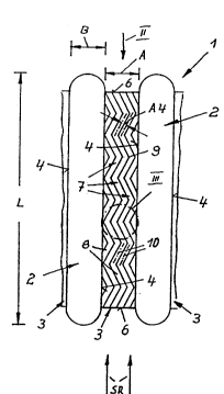
In Fig8 . 1 - 3, ~ portion of a f inned tube heat exchanger f or
the cotlt~er~tion of the exhau~t ~team~ of large turbine plant~ of
cooling air i~ denot~sd by L.
The f i~e~ tube heae exchanger 1 ~a~ ~eve~ heat exchanger
tuk~e6 2 having a~ ol~ on~ cross ~e~t ' o~, whe~ein the ~ea~ exch~nge~
l0/26~1995 18: 46 121~gg634~l FRIE~lCH ~UEFFNER P~GE 1
~l~2a~l
tubes 2 a~e arrange~ parallel and next to one another at a dist~nce
A. The heat ~x~h~nger tube~ ~ are conne~ted to one another hy fins
3 which ex~end paralle~ to the flow direction SR of ~he cooling air
and are fastene~ ~y Rui~le f ixing ~trips pe~pendicular~ y ~n the
lateral ~urf~ce~ . of the heae ~ h~nger tube~ ~.
Fig. 1 shows that the lenyth L of the ~ros~ section of the
heat ~Y~h~nyer tu~e~ 2 i~ greater by a rnult1ple th~n the wi~th B.
The f in~ 3 aLL~y~d at a ~i~tance Al of 3 ~m ~rom each other
~ig~. 2 an~ 5) ha~e on bo~h ~ide surf~e~ 5 conti.fluo~s air
cor.~u~tion groove~ 7 w~ich are ar~ange~ in a ~ig- zag - shaped
configuration parallel next to one another and ex~end in flow
di.rection SR of ~he coolin~ ~ir. The air conduction groove~. 7 are
c~pen at the ends ~ of the fin~. The air conduction groo~e~ are
produced l;~y ~n appropriate ernbo6~ent o~ the fins 3 with a
thieknes~ D of approx~m~tely O .1 r~n in the ea~e of ~lumin~rn or
copper, or of approximate~y ~.5 T~n in the ca~e of steel IFigs. 1 -
5) .
~ ach air c~nductiorl groove 7 i~ colnpoed of ~traight groo~re
section~ ~ and two arc-shaped transi~ on sec~ion~ g which
step~e~ly c~ect two suc~e~ive 9L~VVe ~ections ~ ~Figs. 1, 3 ~nd
4 ) . ~ig. 4 ehowl!3 on ~ lar~er ~cale the geometric condi~ions of an
l0~26~1995 1~:45 121~C`8~3461 FRIE~RICH KUEFFi`~ER P~GE ll
2162~1
air ~o~lt~ction g~Cso~re, with the aid of the center line~ 10 of ~wo
eucce6~ive groo~re sections ~ cho~n in wider lines.
Accordingly, ît ~an be seen that ~he arc~ p~d ~ran~i~iorL
sec~ions 9 are cur~ed in a 8emicircular shape. The cur~ature
ce~te~ points 11 o~ t~.e transition sec~ions 9 are loca~:ed at
diEtance ~rom the ~}~netry line SL of the air conduction ~roove 7.
rhe tra~si~ion ~ections 9 }Lave a r~diu~ ~1 o~ 1. 5 man ~o 3 nm~ rhe
di~tan~e A2 be~ween two transve~3e planes E which in~.ersec~
aucce~8i~re curv~ture ~nt~r poin~ 11 is 10 ~nm. Th~ point 1~ of
inter~ection of the center l ine~ 10 o~ two succ~ssi~re groo~e
~ection~ 8 i8 arranged at a distance A~ of 3..5 m~n fron- ~he ~ymmPt~y
~ine SL.
~ g. 5 ~u~thex chowæ that the air cor~duc~ion groo~es 7 na~re a
~e~i~i~cula~ cr~s ~e~tion with a radiu~ R ~d a d~pth T ~f
The di~t~nce A4 ~etwee~ the ~enter l1ne~ lG of two ~djac~n~
air ~onduct~ on groove~ i~ 5 . 0 ~rrn t~ig~ . 1 and 5 ~ .
The U-~r~4 f in s~trip 1~ of Fi~ . 6 to h iS ~omposed o~ a
pluralit5r of fin~ 3a and the fa~tenin~ ~trips 1~, 14a which connect
the fins 3a and which, simul taneou~ly, ~erve for ~e~uring ~he f in
~erip 13 to ~he he~ ey~h~n~e~ tu}~ The fa~enin~ rip~; ï4
tO
10,~26~19g5 13:46 12129~5346l FRIEDRICH I~IJEFFNER PAGE 12
2152~
extending i~ the pl~ne E~l-El extend parallel to the ~stening
~ip~ 14a whiC~ ~ter~d in the plane E2-E~.
The rib~ 3a are divid~l in lonyi~udinal di~ection into ~f~vFe~al
zi~-zag~h~pe~ ~ucceB~re fiel~ 15 with parz~llel gr~t:}ve sectien~
8d. Al~o in thi~ caRer ~fi in the e~n~odiment of Figs. 1 ~o 5, ,he
g~oove ~ection~ ~a al~e com~c~nents of th~ air cfJn~uction gr~o~es ~a
which extend continuou81y over the length of ~he f in~ 3a .
The longit~ in~l edge~ 17 of th~ f ield~ ~5 extend at the
aI~gle a, al tO the fa~te~; n~ ~t~ip~ 1~ f 14~ extending ~n the
parallel plane~ 1, R2-E2, as well ~ ~t ~he ~ngle ~ to the
pl~ne ~3-33 inter~e~ti ng the longitudin~l edge~ 18, lf of earh ~in
3aL. The angle~ a, ~ 1 are 14.
A~ ~ ~e~u~ e ~f the fieldK 15 extending ohli~uely in ~pa~e and
formed a~out the axe~ exsending through the eent~r FSP of gravity
of the ~urface of the field~ 15, slende~ ~iang~l~r por~iorls ~0 are
formed in longit~ irec:tion of th~ fin~ 3~ be~w~en the
longitl~A-nAl ~dge~ 16, 17 of the field~ ~5 and the lon~it~ in~
edge~ lB, lg of the ~ 3a.
I~e ~nfis~tion of che fin~ ~a and the air c~ndu~tion
~roove~ 7a ~orrned in ~he ~in6 3a otherwi~e corr~pond~ co ~he
lg~26~1gg5 18: 46 1212~868461 ~RIE~PICH KUEFF~EI~ P~iE 18
~20~
c:onfiguratiorl of the rib~ 3 and ~he air conduc~ion grooves 7 of the
en~odiment of Pigæ. ~ to S, ~o th~ not neceæsary ~o r~peat
the ~sxplanation ~