Language selection

Search

Patent 2162205 Summary

Third-party information liability

Some of the information on this Web page has been provided by external sources. The Government of Canada is not responsible for the accuracy, reliability or currency of the information supplied by external sources. Users wishing to rely upon this information should consult directly with the source of the information. Content provided by external sources is not subject to official languages, privacy and accessibility requirements.

Claims and Abstract availability

Any discrepancies in the text and image of the Claims and Abstract are due to differing posting times. Text of the Claims and Abstract are posted:

  • At the time the application is open to public inspection;
  • At the time of issue of the patent (grant).
(12) Patent: (11) CA 2162205
(54) English Title: COIN INSERT
(54) French Title: DISPOSITIF DE DISTRIBUTION ET D'ENCAISSEMENT DE MONNAIE
Status: Expired and beyond the Period of Reversal
Bibliographic Data
Abstracts

English Abstract


The present invention provides an insert to fit into a paper money slot of a
cash drawer to convert that slot into a coin-receiving/dispensing area. The insert comprises
upper and lower sections. The upper section comprises a coin-receiving depression
circumscribed by a flat, upper surface. The lower section comprises a flat base to rest on
the slot bottom when the tray is in position in the slot. Cooperating sleeve and post means
are provided on facing surfaces on the upper and lower sections. The sleeves adjustably
receive corresponding posts in frictional engagement so as to maintain the upper section at
an adjustable height relative to the lower section.


Claims

Note: Claims are shown in the official language in which they were submitted.

- 7 - -
THE EMBODIMENTS OF THE INVENTION IN WHICH AN EXCLUSIVE
PROPERTY OR PRIVILEGE IS CLAIMED ARE DEFINED AS FOLLOWS:-
1. An insert to fit into a paper money slot of a cash drawer to convert that slot
into a coin-receiving/dispensing area, the slot having a bottom and front, back and side walls
vertically disposed circumscribing the slot bottom in rectangular fashion, the insert
comprising upper and lower sections, the upper section comprising a coin-receiving
depression circumscribed by a flat, upper surface, the lower section comprising a flat base
to rest on the slot bottom when the tray is in position in the slot, cooperating sleeve and post
means being provided on facing surfaces on the upper and lower sections, the sleeves to
adjustably receive corresponding posts in frictional engagement so as to maintain the upper
section at an adjustable height relative to the lower section.
2. An insert according to claim 1 wherein the upper surface of the upper section
has edges forming a rectangular periphery, with tear strips being provided along the edges
of an end and two sides of that upper surface so that those upper surface edges can be
trimmed to conform to walls of the slot.
3. An insert according to claim 1 wherein the lower section is of rectangular
shape and provided with upstanding sleeves at corners thereof, corresponding downwardly
depending posts being provided on an undersurface of the upper section.

-8-
4. An insert according to claim 1 wherein the depression is provided with walls
extending downwardly, from the upper surface to the bottom of the depression in curved,
concave fashion.
5. An insert according to claim 2 wherein the depression is provided with walls
extending downwardly, from the upper surface to the bottom of the depression in curved,
concave fashion.
6. An insert to fit into a paper money slot of a cash drawer to convert that slot
into a coin-receiving/dispensing area, the slot having a bottom and front, back and side walls
vertically disposed circumscribing the slot bottom in rectangular fashion, the insert
comprising upper and lower sections, the upper section comprising a coin-receiving
depression circumscribed by a flat, upper surface, the lower section comprising a flat base
to rest on the slot bottom when the tray is in position in the slot, cooperating means being
provided for securing the upper and lower sections together so as to maintain the upper
section at an adjustable height relative to the lower section.

Description

Note: Descriptions are shown in the official language in which they were submitted.


- 1 216220~
BACKGROUND OF THE INVENTION
The present invention relates to an insert to fit into a paper money slot of a
cash drawer to convert that slot to a coin-receiving/dispensing area.
FIELD OF THE INVENTION
As many countries convert paper currency to coin currency, conventional cash
registers and cash drawers used by banks and businesses are becoming increasingly less
useful. This is because such drawers have been designed with slots for a predetermined
number of paper money denominations and have a limited area and limited slots to receive
coinage. Such drawers conventionally have slots with a bottom, and front, back and side
walls, vertically disposed and circumscribing the slot bottom in rectangular fashion. From
side-to-side across the cash drawer may extend, for example, slots to receive, respectively,
twenty dollar, ten dollar, five dollar, two dollar and one dollar denomination paper bills.
PRIOR ART
With respect to such drawers which have been previously designed for a full
range of the most frequently used paper currency, as paper currency is phased out,
increasingly one or more sections which are no longer useful for their original purpose, i.e.
holding paper bills.
C:~n~ n Patent No. 1,284,131 of Clark, issued May 14, 1991, describes and

-2- 2182~5
illustrates a converter for a paper money receiving slot in a cash drawer in the form of a
contoured sheet being formed from flat material of rectangular shape, the sheet to fit within
the slot and curved to facilitate receiving and dispensing coins on the sheet when in position
in the section. House U.S. Patent No. 2,155,549 issued April 25, 1939 describes and
5 illustrates an alternative form of curved sheet insert for cash drawers or the like. C~n~ n
Laid-Open Patent Application Serial No. 2,144,095 of Bonneville published April 7, 1995
describes and illustrates a plastic, cup-shaped insert for such slots. Hutchinson U.S. Patent
No. 4,314,632 issued February 9, 1982 describes and illustrates an elongated, double-
bottomed insert for a slot of a till, the insert having, at one end, a flat upper surface with
10 trim tabs removable to ensure that the insert will slide within the walls of the slot. Other
references of general background interest fe~tllring removable pockets or inserts for cash
registers or the like are U.S. Patent No. 1,349,527 of Owen issued August 10, 1920, U.S.
Patent No, 2,681,730 of Carney issued June 22, 1954, European Patent Application No.
90301200.3 of Gomi, et al published under Publication No. 0,383,468, and C~n~ n Laid-
Open Patent Application No. 2,096,110 of Nygard et al published July 12, 1992.
None of these prior art devices is particularly well-suited to be adaptable for
a wide variety of shapes and sizes of slots in money drawers and the like. While such slots
may be, generally speaking, of roughly equivalent dimensions, frequently there are small but
significant variations in, for example, the width or length of the slots or the heights of the
20 circumscribing the walls.
OBJECTS OF THE PRESENT ~VENTION

- 3 - ~162~5
It is thus an object of the present invention to provide an insert which will be
easily adaptable to fit a variety of such paper currency-receiving slots of cash drawers, to
convert them to easily and conveniently receive and dispense coins.
SIJMMARY OF TIIE I~VENTION
S In accordance with the present invention there is provided an insert to fit into
a paper money slot of a cash drawer to convert that slot into a coin-receiving/dispensing
area. The insert comprises upper and lower sections. The upper section comprises a coin-
receiving depression circumscribed by a flat, upper surface. The lower section comprises
a flat base to rest on the slot bottom when the tray is in position in the slot. Means for
adjustably securing the upper section to the lower section, such as cooperating sleeve and
post means, are provided, preferably on facing surfaces of the upper and lower sections, the
sleeves being adjustably received in corresponding posts in frictional engagement. The
securing means are constructed so as to m~int~in the upper section at an adjustable height
relative to the lower section.
In a preferred embodiment of the present invention the upper surface of the
upper section has edges forming a rectangular periphery, with tear strips being provided
along the edges of an end and two sides of that upper surface so that the upper surface edges
can be trimmed to conform to walls of the slot.
The insert in accordance with the present invention will attractively fit into
different slots of cash drawers where the wall height from one slot to another may differ and,
in the preferred embodiment having tear strips, where the width or length of the varying slots

4 2182205
may differ. In the former, the height of the upper section relative to the lower section may
be suitably adjusted for the particular wall height of the slot; in the latter case tear strips as
required may be removed, so that the peripheral of the edges of the upper surface of the
upper section conform more or less to the circumscribing walls of the slot.
S BRIEF DESCRIPTION OF THE DRAWINGS
These and other advantages of the invention will become apparent upon
reading the following detailed description and upon referring to the drawings in which:-
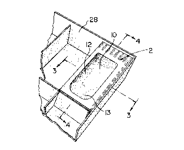
FIGURE 1 is a perspective view of a portion of a cash drawer having a slot
into which an insert in accordance with the present invention has been fitted;
FIGURE 2 is an exploded, perspective view of the insert of FIGURE l;
FIGURE 3 is a section view along line III-III of FIGURE l; and
FIGURE 4 is a section view along line IV-IV of FIGURE 1.
While the invention will be described in conjunction with an example
embodiment, it will be understood that it is not intended to limit the invention to such
embodiment. On the contrary, it is intended to cover all alternatives, modifications and
equivalents as may be included within the spirit and scope of the invention as defined by the
appended claims.
DETAILED DESCRIPTION OF THE INVENTION
In the following description, similar features in the drawings have been given

5 2i6~2~
similar reference numerals.
Turning to FIGURE 1, there is illustrated an insert 2 having an upper section
4 and a lower section 6 (FIGURE 2).
Upper section 4 is provided with a coin-receiving depression 8 having a
S relatively flat bottom 10, and concavely-shaped side walls 12 and front wall 13 (FIGURES
3 and 4).
At the top of walls 12 and 13 of depression 8 and circumscribing that
depression is a flat upper surface 14 of rectangular periphery. As can be seen for example
in FIGURE 3, at least one of the side edges 16 of upper surface 14 is provided with a
plurality of trim strips 18. Rear edge 20 of upper surface 14 is simil~rly provided with a
plurality of trim strips 22. It will be understood that one or more of these trim strips may
be removed, as required, to ensure that the peripheral edges of upper surface 14 are more
or less contiguous with the upper ends of circumscribing walls 24 of a slot 26 in a cash
drawer 28, into which the insert 2 is fitted.
Lower section 6 essentially comprises a flat rectangular base 30 to be seated
on bottom 32 of slot 26 in cash drawer 28 (FIGURE 4). If desired, securing means such as,
for example, double-sided adhesive strip 34, may be placed on the underside of base 30, to
ensure that insert 2 is firmly seated within slot 26 and does not move relative thereto.
To secure upper section 4 at a particular height with respect to lower section
6, post 36, downwardly depending from a bottom surface of flat upper surface 14 are
frictionally engaged within sleeves 40 upwardly extending from base 30 of lower section 6,
as illustrated. In the illustrated embodiment, sleeves 40 are located at each of the corners
of base 30. Posts 36 are snugly received within sleeves 40 so that they friction fit within the

- 216Z2Q5
- 6 -
sleeves at adjustable heights. This feature is important since it is necessary that the relative
height of upper section 4 with respect to lower section 6 be adjustable and be m~int~hle at
a selected height, to suit for varying heights of walls 24 in different slots of dirrerelll cash
drawers. This feature and the trim strips 18 and 22 make it possible for a single size of
5 insert 2 to be provided, that size to fit multiple sizes of slots 26 by removing appropriate
numbers of trim strips 18 and 22 for conforming the length and width of upper section 4 to
meet the walls of 24 of slots 26, and by adjusting the height of posts 36 in sleeves 40 to
ensure that the upper surface 14 of insert 2 is more or less the same height as the upper
edges of walls 24 of the slot 26 within which insert 2 is fitted.
Thus, it is apparent that there has been provided in accordance with the
invention an insert for converting paper money-receiving slots of cash drawers to coin-
receiving slots, that fully satisfies the objects, aims and advantages set forth above. While
the invention has been described in conjunction with a specific embodiment thereof, it is
evident that many alternatives, modifications and variations will be apparent to those skilled
15 in the art in light of the foregoing description. Accordingly, it is intended to embrace all
such alternatives, modifications and variations as fall within the spirit and broad scope of the
invention.

Representative Drawing
A single figure which represents the drawing illustrating the invention.
Administrative Status

2024-08-01:As part of the Next Generation Patents (NGP) transition, the Canadian Patents Database (CPD) now contains a more detailed Event History, which replicates the Event Log of our new back-office solution.

Please note that "Inactive:" events refers to events no longer in use in our new back-office solution.

For a clearer understanding of the status of the application/patent presented on this page, the site Disclaimer , as well as the definitions for Patent , Event History , Maintenance Fee  and Payment History  should be consulted.

Event History

Description Date
Time Limit for Reversal Expired 2008-11-06
Letter Sent 2007-11-06
Inactive: IPC from MCD 2006-03-12
Inactive: Late MF processed 2004-11-09
Letter Sent 2004-11-08
Inactive: Late MF processed 2003-11-06
Letter Sent 2002-11-06
Grant by Issuance 1999-03-16
Inactive: Final fee received 1998-11-27
Pre-grant 1998-11-27
Notice of Allowance is Issued 1998-05-28
Letter Sent 1998-05-28
Notice of Allowance is Issued 1998-05-28
Inactive: Status info is complete as of Log entry date 1998-05-21
Inactive: Application prosecuted on TS as of Log entry date 1998-05-21
Inactive: Approved for allowance (AFA) 1998-04-30
Application Published (Open to Public Inspection) 1997-05-07
All Requirements for Examination Determined Compliant 1996-02-06
Request for Examination Requirements Determined Compliant 1996-02-06

Abandonment History

There is no abandonment history.

Maintenance Fee

The last payment was received on 1998-11-03

Note : If the full payment has not been received on or before the date indicated, a further fee may be required which may be one of the following

  • the reinstatement fee;
  • the late payment fee; or
  • additional fee to reverse deemed expiry.

Patent fees are adjusted on the 1st of January every year. The amounts above are the current amounts if received by December 31 of the current year.
Please refer to the CIPO Patent Fees web page to see all current fee amounts.

Fee History

Fee Type Anniversary Year Due Date Paid Date
MF (application, 2nd anniv.) - small 02 1997-11-06 1997-11-06
MF (application, 3rd anniv.) - small 03 1998-11-06 1998-11-03
Final fee - small 1998-11-27
MF (patent, 4th anniv.) - small 1999-11-08 1999-11-08
MF (patent, 5th anniv.) - small 2000-11-06 2000-11-06
MF (patent, 6th anniv.) - small 2001-11-06 2001-11-06
MF (patent, 7th anniv.) - small 2002-11-06 2003-11-06
MF (patent, 8th anniv.) - small 2003-11-06 2003-11-06
Reversal of deemed expiry 2004-11-08 2003-11-06
MF (patent, 9th anniv.) - small 2004-11-08 2004-11-09
Reversal of deemed expiry 2004-11-08 2004-11-09
MF (patent, 10th anniv.) - small 2005-11-07 2005-11-07
MF (patent, 11th anniv.) - small 2006-11-06 2006-08-22
Owners on Record

Note: Records showing the ownership history in alphabetical order.

Current Owners on Record
DAVID J. RANDEN
Past Owners on Record
None
Past Owners that do not appear in the "Owners on Record" listing will appear in other documentation within the application.
Documents

To view selected files, please enter reCAPTCHA code :


To view images, click a link in the Document Description column. To download the documents, select one or more checkboxes in the first column and then click the "Download Selected in PDF format (Zip Archive)" or the "Download Selected as Single PDF" button.

List of published and non-published patent-specific documents on the CPD .

If you have any difficulty accessing content, you can call the Client Service Centre at 1-866-997-1936 or send them an e-mail at CIPO Client Service Centre.


Document
Description 
Date
(yyyy-mm-dd) 
Number of pages   Size of Image (KB) 
Description 1996-03-26 6 223
Abstract 1996-03-26 1 18
Claims 1996-03-26 2 61
Drawings 1996-03-26 2 51
Representative drawing 1999-03-11 1 14
Representative drawing 1997-07-09 1 12
Reminder of maintenance fee due 1997-07-07 1 111
Commissioner's Notice - Application Found Allowable 1998-05-27 1 164
Maintenance Fee Notice 2002-12-03 1 173
Maintenance Fee Notice 2002-12-03 1 174
Late Payment Acknowledgement 2003-11-16 1 166
Maintenance Fee Notice 2004-12-01 1 173
Late Payment Acknowledgement 2004-12-01 1 166
Maintenance Fee Notice 2007-12-17 1 173
Fees 2003-11-05 1 30
Fees 2003-11-05 1 32
Correspondence 1998-11-26 1 45
Fees 2001-11-05 1 30
Fees 1998-11-02 1 40
Fees 1997-11-05 1 41
Fees 1999-11-07 1 39
Fees 2000-11-05 1 31
Fees 2004-11-08 1 26
Fees 2005-11-06 1 25
Fees 2006-08-21 1 28