Note: Descriptions are shown in the official language in which they were submitted.
`_ 2 1 6 2 ~ 8 0 ~fE~1533 AS ORIGI~:ALLY FILED
Refillable Package
This invention relates to a refillable package comprising a
housing and an exchangeable fillable container so that said
package can be refilled without any pouring and/or
transfusing of the substance to be dispensed. This way,
clean, hygienic and lossfree refilling can be ensured.
US-4,469,250 discloses a refillable package with a
squeezable container and an exchangeable bladder. Said
container consists of an upper portion and a lower portion,
which secure said bladder inbetween when screwed together.
In addition, said upper portion comprises a first one-way
check valve for dispensing the contents of said bladder and
said lower portion comprises a second one-way check valve
disposed to permit air flow from outside into the space
between said bladder and said container. When emptied, said
container is squeezed together and the contents of said
bladder is squeezed out via said first one-way check valve.
The vacuum in said container produced by the loss of
contents is balanced by supplying air via the second one-way
check valve. Underneath the container thread, the bladder
hangs unsecured in the container.
US-5,156,299 relates to a refillable package consisting of a
two-part container with a manual pump head and an
exchangeable bladder. The side walls of said bladder are
provided with grooves or folds connected to the opening of
said bladder which are to facilitate the transport of the
liquid from all parts of the bladder. The only connection of
said bladder with said container is in the area of the
opening of said bladder.
In refillable packages, one problem is to equally empty the
substance to be dispensed since the bladder, bladder or bag
tends to collapse when partially emptied and, when the
dispensing process is caused by air pressure, this causes
~ ~ 1 6 2 ~ 8 ~ 1533 AS ORIGL~'ALLY FILED
the pressure to decrease. The described state of the art
tries to solve this problem by means of increased technical
expenditure. US-4,469,250 teaches to balance the pressure
loss by means of the second one-way check valve, and US-
5,156,299 uses a pump head and product flow channels in the
bladder.
In contrast, the object of this invention is to provide a
refillable package comprising a housing and an exchangeable
container, having a simple and inexpensive design, and
wherein collapsing of said container is reliably prevented
when said container is emptied.
Advantageously, the container according to this invention is
of low volume and weight so that only little waste will
occur. The housing can be reused several times and, if
desired, can be elaborately designed.
This object is achieved by means of the features of the
claims.
The solution according to this invention is based on the
principle idea to provide at least one guide means on the
sides of said container engaging with at least one
corresponding mounting in said housing. This way said
container is stabilized in its position within said housing
and prevented from collapsing even when completely or
partially empty. Thus, said container can be reliably and
completely emptied.
The advantage of this invention lies in a simple and
inexpensive production of said refillable package, in a
user-friendly usability and a wide variety of applications,
e.g. for liquid, viscous or powdery substances. Besides, the
housing can be adjusted to an appearance of known vessels
without internal containers and replace them.
`- 216~4~0
PCr/EP~,31533 AS ORIGI;;ALLY FILED
In the following, the invention is explained in more detail
based on the Figures:
Fig. 1 shows a cross-sectional view of an embodiment of
this invention;
Fig. 2 shows a cross-sectional view of another embodiment
of this invention;
Fig. 3 shows a cross-sectional view along the line A-A' of
Fig. 2;
Fig. 3a is an enlarged depiction of the upper portion of
the embodiment of this invention of Fig. 3;
Fig. 4 shows a cross-sectional view through part lb of
Fig. 2;
Fig. 5 shows a side view of part lb with bars of Fig. 3;
Fig. 6 shows a side view of the container of Fig. 2;
Fig. 7 shows a side view of the container of Fig. 3;
Fig. 8 shows a side view of the container of Fig. 6
mounted on the part lb of Fig. 4;
Fig. 8a shows a side view of a container mounted on part lb
in another embodiment of this invention;
Fig. 9 shows a side view of the mounted container of
Fig. 8 perpendicular to the drawing plane;
Fig. 10 shows a top view of the mounted container of
Fig. 8;
Fig. 11 shows a cut through an embodiment of the invention
with level control;
- 2162~8~
K'r'LP~A)15;3 AS ORlCil~JALLY FIII~D
Fig. 12a shows a cross-sectional view of another embodiment
of this invention;
Fig. 12b shows a cross-sectional view along the line B-B' of
Fig. 12a;
Fig. 12c shows an enlarged detail of Fig. 12b;
Fig. 13a shows a cross-section through another embodiment of
this invention with guide means for the container
integrated in the housing wall;
Fig. 13b shows a cross-section through another embodiment of
this invention with bars upright projecting from
the bottom of the housing as guide means for the
container;
Fig. 13c shows a cross-section through another embodiment of
this invention with a guide ring only partially
surrounding the container;
Fig. 14a shows a cross-section through another embodiment of
this invention;
Fig. 14b shows an enlarged detail of Fig. 14a;
Fig. 14c shows a cross-section through Fig. 14b
perpendicular to the drawing plane;
Fig. 15a shows the assembled embodiment of this invention of
Fig. 14a;
Fig. 15b shows a top view of the embodiment of the invention
of Fig. l5a;
Fig. 16a shows a side view of the closed embodiment of the
invention of Fig. 15a with cut upper portion;
2 1 6 2 4 8 0 PCT,'EPW,01533ASORIGL~ALLYFQED
Fig. 16b is an enlarged depiction of the cut area of Fig.
16a;
Fig. 17a shows the embodiment of this invention of Fig. 15a
ready for dispension;
Fig. 17b shows a top view of the embodiment of this
invention of Fig. 17a;
Fig. 18 shows a cross-section through another embodiment of
this invention;
Fig. l9a shows a cross-section through another embodiment of
this invention;
Fig. l9b shows a top view of the embodiment of this
invention of Fig. l9a, wherein the housing is cut
perpendicular to the drawing plane;
Fig. l9c is an enlarged depiction of Fig. l9b;
Fig. 20a shows the container of ~ig. 19 in a partially cut
side view; and
Fig. 2Ob shows a front view parallel to the drawing plane of
the embodiment of the invention of Fig. 20a.
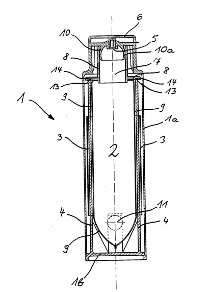
Fig. 1 shows a cross-section through an embodiment of the
refillable package of this invention, which exhibits an oval
shape with two wide and two narrow sides in the cross-
section parallel to the drawing plane. The cross-section
depicted in Fig. 1 runs through the center axis
perpendicular to the wide sides of an outer housing 1. A
container 2 comprises loops 3, which are pushed over bars 4,
and with the flange 8 surrounding a container opening 7
rests on the upper ends 13 of said bars 4 in recesses 14.
Said housing 1 comprises a first part la and a second part
2 ~ ~i 2 4 8 0 P~ r 1 533 AS ORIClt~'ALLY FILED
lb which are detachably connected to one another via at
least one locking means 11 (below and/or above the drawing
plane). Said part la comprises a dispensing means 5 for the
substance, a closure cap 6 and a connection piece 10 at its
upper end. When said parts la and lb are connected with one
another, the connection piece 10 engages with the container
opening 7 and seals it against the flange 8 by means of a
seal lOa. If said opening 7 of said container 2 is covered
by a film before the assembly of said container 1, the film
is pierced by said connection piece 10 when said housing
parts la and lb are connected with one another. Said housing
1 and said container 2 are preferably made of plastics, said
housing being stiff but flexible and said container being a
film bag 9. In order to empty said bag 2, said housing 1 is
squeezed by the user's hand and the pressure is transferred
to said bag 2 causing its content to be dispensed via the
dispensing means 5 when said closure cap 6 is open. The
compressed housing 1 changes the shape of said bars 4 to a
certain extent. Then these bars 4 pull said bag 2 back into
its starting position when said housing 1 is let go with the
result that said bag 2 is supplied with air again.
The design according to this invention with said bag guided
in said mountings of a housing also allows for a simple
pouring out of said refillable package without applying any
pressure.
Fig. 2 shows a preferred location of said bars 4. It is
advantageous if they are located on the wide sides of said
housing 1 and outside the center. This allows for the
pressure to be transferred to said bag 2 via the sides of
said housing 1, which are preferable lower in their wall
thickness in the pressure area, without being affected by
said bars 4.
Fig. 3 shows a cross section through the embodiment of Fig.
2 along the line A-A'.
`~ 216248~
PCT/EW4,01533 AS ORIGI~IALLY FILED
Fig. 3a is an enlarged depiction of the upper portion of
said refillable package of Fig. 3 comprising said connection
piece 10 and said seal lOa.
Figs. 4 and 5 show said second part lb of said housing
comprising said bars 4, and Figs. 6 and 7 show corresponding
depictions of the matching bag 2 with loops 3 for said bars
4. Preferably, said bag consists of a transparent film
welded together at its edges, wherein said film is printed
only partially so that the substance level can be visually
controlled. Said loops 3 are preferably connected to the bag
envelope 9 by means of welding. In addition, as shown in
Fig. 11, there are several transparent windows 15 provided
in the side wall of said housing 1 to make it possible to
control the substance level in said bag 2.
Figs. 8 and 9 show front and side views of the bag of Figs.
6 and 7, mounted by means of said bars 4 onto said second
part lb. Two locking means 11 are provided on said second
part lb. When said housing is closed, the protruding locking
means are engaged with holes 12 in said first part la of
said container 1 (see also Fig. 2). Part la can easily be
removed from part lb by means of exerting pressure on the
elastically held protrusion 11.
Fig. 8a shows another embodiment according to this invention
of mounting said bag 2 on said part lb. In this embodiment,
said bars 4 as well as said loops 3 taper off upwardly
and/or they are wedge-shaped. This renders the insertion of
said bag 2 into said part lb easier for the user.
Fig. 10 shows a top view of the mounted bag of Figs. 8 and
9.
Fig. 11 shows a cut through the embodiment of the invention
of Fig. 1 perpendicular to the drawing plane. The elongated
holes drawn in broken lines represent transparent windows 15
located in said side wall la of said housing, making it
~- 2162480
1533 AS ORIGINALLY FILED
possible to control the substance level in said bag 2, which
is transparent underneath said transparent window 15.
Figs. 12a to d show another embodiment of this invention.
Fig. 12a shows the embodiment of this invention cut open. On
its outside, said bag 2 comprises an injection-molded
surrounding ring 16 as mounting guided in two bars 4 (only
one is visible). As can be seen in the cross-section (Fig.
13b), said bars, which stand freely on the housing bottom,
comprise a dove-tail shape 18, wherein the dove tail 18 is
guided in dove-tail grooves 17 of said ring 16.
Fig. 12b shows a cross-sectional view along the line B-B' of
Fig. 12a. With regard to the other features of this
embodiment, reference is made to the above description e.g.
of Fig. 1. Fig. 12c shows an enlarged detail of said ring 16
and said dove-tail guide 17, 18 in said bar 4.
Figs. 13a to c show various embodiments of this invention of
said guide means and mounting of said bag in said housing.
Fig. 13a shows the mounting of said bag as an integrated
component 19 of said container wall lb. In its cross-
section, the means 19 comprises a hollow dove-tail shape,
which is engaged with a corresponding groove in said ring
16. The hollow dove-tail shape ensures an elastic
deformation when said housing wall is squeezed together.
Fig. 13b shows an alternative mounting of said bag inside
said housing. Fig. 13c shows an embodiment of this
invention, wherein said ring 16 of the embodiment of the
mounting according to Fig. 13a only partially surrounds said
bag 2. This makes it easier for said bag to be squeezed
together when being emptied. As in the embodiments according
to Figs. 1 to 11, the embodiments of this invention
according to Figs. 13a to 13c comprise a thinner wall in the
direction of the shorter axis of said housing 1 in its
pressure area, which also makes it easier to squeeze said
housing together when emptying said bag 2.
2 1 6 2 4 8 0 PC'F'EPUA~1533 AS ORIGI~ LLY FILED
Figs. 14a to 17b show another embodiment of the invention.
In this embodiment, said ring 16 does not completely
surround said bag 2 (see Fig. 13c), and said flange 8, said
first part la and said closure cap 6 differ from the
embodiments shown so far.
Fig. 14a shows said bag and said housing in an unassembled
state. Said bag 2 is introduced into said dove tails
integrally connected with said second housing part lb by
means of dove-tail grooves on said ring 16, pushed into said
second housing part lb, and then said part lb is connected
with said first housing part la. Said flange 8 comprises a
membrane 21 at its upper end comprising a dispensing opening
7, which is closed by means of an insert 22 before said
first dispensing. This insert 22 serves as a tamper proof
seal, which is grabbed and removed by means of hooks 24
within said closure cap 6 when said bag is first opened.
Fig. 14b shows an enlarged depiction of the membrane 21 and
said insert 22 of Fig. 14a. Said membrane 21 comprises a
surrounding swelling 26 at its side to prevent said insert
22 from being taken off. Said membrane 21 elastically and
resiliently pushes against a stopper 22a of said insert 22
protruding downwards and thus seals the dispensing opening
7. Fig. 14c shows a cross-section through Fig. 14b
perpendicular to the drawing plane. There are two opposite
comb-like recesses 23 in the swelling 26, into which the
hooks 24 snap when said closure cap 6 is closed and they
thus snap behind said insert 22. Fig. 15a shows said housing
1 with said bag 2 in an assembled state. Said insert 22
closes said opening 7, i.e. the tamper proof seal is not yet
removed when said closure cap 6 is open. Fig. 15b shows a
top view of the embodiment of the invention of Fig. 15a.
Upon closing the lid 6, said hooks 24 snap behind said
insert 22 (Fig. 16a and enlarged depiction Fig. 16b). The
curvature of said insert 22 lies inside a corresponding
indentation 25 of said closure cap 6. When said closure cap
62q80
PCr~EP94.~1533 AS ORIGINALLY FILED
6, which is movably mounted on part la e.g. by means of
hinges, is tilted, said insert 22 is removed from said
opening 7 and thus exposes said bag 2 for a first
dispension. This state is depicted in a cross-sectional view
in Fig. 17a and in a top view in Fig. 17b. Said insert 22,
held by said hooks 24, remains inside said closure cap 6 and
seals off said bag 2 when said housing 1 is closed. When a
new bag 2 with a new insert 22 is inserted, the old insert
22 is removed from said closure cap 6 by pushing it to the
side, and the process of removing the tamper proof seal in
the form of said insert 22 is repeated as described above,
said new insert 22 remaining inside said closure cap 6.
The above-described flange 8 can be used according to this
invention in various containers.
Fig. 18 shows another embodiment of this invention, wherein
said flange 8 is depicted only schematically, but
corresponds to the embodiment of Figs. 15a and b. Said bag 2
comprises surrounding rings 20 on its inside, spreading the
wall of said bag open and enforcing it (Fig. 18 shows two
rings). After said bag 2 has been inserted into said second
housing part lb, said rings 20 are form-fit with said
housing 1 via said wall of said bag 2, with said wall of
said part lb serving as a mounting. Said rings 20 reliably
prevent the empty bag 2 from collapsing and allow an elastic
squeezing together of said bag 2 when emptying it.
Alternatively, said bag can comprise only one ring. Said
ring(s) can be open and/or spiral-shaped.
Figs. l9a to c and 20a and b show another embodiment of this
invention.
Fig. l9a shows a refillable package with said container 2
being self-supporting and thin-walled. This kind of
container is preferably blown, which process makes very thin
walls possible. Said flange 8 with said container opening 7
is formed directly onto said container 2. Said flange 8 can
~_ 21~24~0
11 K'r/EW-,01533 A~5 ORIGI:`IALLY FIII~D
also be in the two-part form. First, a large hole is
provided for a better filling of said container 2, which
hole is then closed by means of an intermediate ring
comprising said container opening 7 and said insert 22.
Fig. l9b shows a top view of the embodiment of this
invention of Fig. l9a, wherein said housing 1 is cut open.
Fig. l9c is an enlarged depiction of Fig. l9b. Said
container 2 comprises dove tails 18 on both sides. During
recharging, the latter is inserted in dove-tail grooves 17
located at said housing part lb and thus holds said
container 2 inside said housing 1. Fig. 20a shows said
container 2 of Figs. l9a to c in a partly cut side view.
Fig. 20b shows a front view parallel to the drawing plane of
the embodiment of the invention of Fig. 20a. Said dove tails
18 located on both sides can have different lengths, wherein
one dove tail can also be located at a different hight than
the other one. This can make it easier for the user to
insert said container 2 into said housing 1.
Preferably, the refillable package is for containers having
a cubic content of 125, 250 or 500 ml. However, refillable
packages for larger containers can also be produced.
The refillable package can be used for beverages, foodstuffs
(e.g. Ketchup), cosmetics, detergents, paints, adhesives,
powders, graphite powder, and other things.
The invention can be modified in various ways. For instance,
said container and/or said bag 2 can comprise strips instead
of loops 3 which are engaged with rails instead of said bars
4 in said housing.
An embodiment with e.g. a pair of loops 3 and a pair of bars
4 each being arranged in the largest distance from one
another quasi diagonally from one another is also possible.
By means of a suitable closure, e.g. with a wider opening
perpendicularly above said container opening 7, the content
'_ 21629gQ
PCT!EW~ )1533 ~5 ORlGl.~iALLY FILED
12
of said container 2 can e.g. also be sucked out using a
straw. This embodiment can be used filled with milk, fruit
juice, etc., e.g. when used as a drinking utensil. Due to
the fact that said bars 4 can vary in design and location,
said housing 1 can be designed rather freely (freeform).
Thus, said housing 1 can be designed like a known bottle
without container.