Language selection

Search

Patent 2162551 Summary

Third-party information liability

Some of the information on this Web page has been provided by external sources. The Government of Canada is not responsible for the accuracy, reliability or currency of the information supplied by external sources. Users wishing to rely upon this information should consult directly with the source of the information. Content provided by external sources is not subject to official languages, privacy and accessibility requirements.

Claims and Abstract availability

Any discrepancies in the text and image of the Claims and Abstract are due to differing posting times. Text of the Claims and Abstract are posted:

  • At the time the application is open to public inspection;
  • At the time of issue of the patent (grant).
(12) Patent: (11) CA 2162551
(54) English Title: TUNDISH IMPACT PAD
(54) French Title: AMORTISSEUR DE PANIER DE COULEE
Status: Term Expired - Post Grant Beyond Limit
Bibliographic Data
(51) International Patent Classification (IPC):
  • B22D 41/00 (2006.01)
(72) Inventors :
  • ZACHARIAS, DONALD RICHARD (United States of America)
(73) Owners :
  • FOSECO INTERNATIONAL LIMITED
(71) Applicants :
  • FOSECO INTERNATIONAL LIMITED (United Kingdom)
(74) Agent: GOWLING WLG (CANADA) LLP
(74) Associate agent:
(45) Issued: 2000-08-01
(22) Filed Date: 1995-11-09
(41) Open to Public Inspection: 1996-05-10
Examination requested: 1996-06-11
Availability of licence: N/A
Dedicated to the Public: N/A
(25) Language of filing: English

Patent Cooperation Treaty (PCT): No

(30) Application Priority Data:
Application No. Country/Territory Date
08/338,123 (United States of America) 1994-11-09
9508070.1 (United Kingdom) 1995-04-20

Abstracts

English Abstract

A tundish impact pad (20) to reduce turbulence in the tundish comprises a body of refractory material capable of withstanding contact with molten steel in a tundish (10), the body comprising a base (22) having an impact surface (24), an outer sidewall (26, 40) extending upwardly from the impact surface (24), a top surface (32) connected to the sidewall (26, 40) and defining an opening (30) therein, in which the top surface (32) has an inner annular portion (42) substantially parallel to the impact surface (24), and the sidewall (26, 40) has an interior face (28) which is substantially perpendicular to the impact surface (24) and wherein a substantially right angle corner (28A) is provided between the interior sidewall face (28) and the impact surface (24) and a substantially right angle corner is provided between the interior sidewall face (28) and the top surface inner annular portion (42).


French Abstract

Une plaque d'amortissement de panier de coulée (20) pour réduire la turbulence dans le panier de coulée comprend un corps de matériau réfractaire capable de supporter un contact avec de l'acier en fusion dans un panier de coulée (10), le corps comprenant une base (22) qui comporte une surface d'impact (24), une paroi latérale extérieure (26, 40) qui s'étend vers le haut à partir de la surface d'impact (24), une surface supérieure (32) qui est raccordée à la paroi latérale (26, 40) et dans laquelle est définie une ouverture (30), la surface supérieure (32) comportant une partie annulaire intérieure (42) sensiblement parallèle à la surface d'impact (24), et la paroi latérale (26, 40) comporte une face intérieure (28) qui est sensiblement perpendiculaire à la surface d'impact (24), un coin sensiblement à angle droit (28A) étant prévu entre la face de paroi latérale intérieure (28) et la surface d'impact (24) et un coin sensiblement à angle droit étant prévu entre la face de paroi latérale intérieure (28) et la partie annulaire intérieure de surface supérieure (42).

Claims

Note: Claims are shown in the official language in which they were submitted.

-8-
CLAIMS
1. A tundish impact pad (20) comprising a body of refractory
material capable of withstanding contact with molten steel in a tundish
(10), the body comprising a base (22) having an impact surface (24), an
outer sidewall (26, 40) extending upwardly from the impact surface (24),
a top surface (32) connected to the sidewall (26, 40) and defining an
opening (30) therein, characterised in that the top surface (32) has an
inner annular portion (42) substantially parallel to the impact surface
(24), and the sidewall (26, 40) has an interior face (28) which is
substantially perpendicular to the impact surface (24) and wherein a
substantially right angle corner (28A) is provided
between the interior sidewall face (28) and the impact
surface (24) and a substantially right angle corner is
provided between the interior sidewall face (28) and the
top surface inner annular portion (42).
2. A tundish impact pad according to Claim 1, wherein the
opening (30) has a long dimension (30') and a short dimension (30")
perpendicular to the long dimension.
3. A tundish impact pad according to Claim 2, wherein the
opening (30) is rectangular or oval.
4. A tundish impact pad according to Claim 1, wherein the top
outer surface (32) of the pad is parallel to the impact surface (24).
5. A tundish impact pad according to Claim 1, wherein the
sidewall (26, 40) is endless.

-9-
6. A tundish impact pad according to Claim 1, wherein the pad (20) is a
monolithic refractory having an alumina content of from 55% to 85% by weight.
7. A tundish impact pad according to Claim 1, wherein the pad (20) is a
monolithic refractory comprising magnesia and containing from 58% to 93% by
weight of magnesia.
8. A tundish (10) for holding a volume of molten steel (16) and having a
floor (15) and sidewalk (12) enclosing a region of impact and a drain (14),
wherein
the tundish (10) contains an impact pad (20) as claimed in any one of Claims 1-
7 on
the floor (15) in the region of impact.
9. A tundish according to Claim 8 wherein the tundish has a longitudinal
axis and wherein the impact pad (20) has an opening (30) to receive a stream
of
molten metal, the opening (30) having a long dimension (30') and a short
dimension
(30") perpendicular to the long dimension (30') and the long dimension (30')
of the
opening (30) is aligned with the longitudinal axis of the tundish.

Description

Note: Descriptions are shown in the official language in which they were submitted.


~~.6~~51
- 1 - FS 1554
TUNDISH IMPACT PAD
This invention relates to a tundish impact pad, i.e. a pad of
erosion resistant material positioned on the floor of a tundish to receive
the incoming stream of molten metal poured into the tundish from a
ladle.
U.S. patent 5169591 discloses an impact pad for a tundish
for continuous casting of steel that comprises a base, a peripheral top
surface and a discontinuous sidewall extending between the base and
the peripheral top surface, the sidewall having an undercut inner
surface, which may be curvilinear.
U.S. patent 5358551 discloses an impact pad which
comprises a base, a sidewall extending around the base, the sidewall
having an inner surface having a portion which extends inwardly and
upwardly. That inner surface may be concave.
Whereas both of the aforesaid types of impact pad are
designed to reduce turbulence in the tundish, we have surprisingly
found that improved turbulence reduction can be achieved by providing
an impact pad with internal corners defined between its base, its
peripheral wall and its upper surface. Thus, we have now found that it
can be advantageous to provide such internal corners and that
improvements in the reduction of surface turbulence, minimisation of
slag entrainment, prevention of break-up of tundish flux cover,
reoxidation of the molten steel and ensuring a proper flow path of the
steel within the tundish, may be achieved.

#~ ~ ..
2162~~1
FS 1554
Accordingly, in one aspect, the invention provides a tundish
impact pad comprising a body of refractory material capable of
withstanding contact with molten steel in a tundish; the body
comprising a base having an impact surface, an outer sidewall
extending upwardly from the impact surface, a top surface connected to
the sidewall and defining an opening therein, the top surface having an
inner annular portion substantially parallel to the impact surface and
the sidewall having an interior face which is substantially perpendicular
to the impact surface and wherein a substantially right angle corner is
provided between the interior sidewall face and the
impact surface and a substantially right angle corner is
provided between the interior sidewall face and the top
surface inner annular portion.
Molten steel entering through the opening and contacting
the impact surface flows outwardly , then is turned inwardly by the
sidewall interior face and then flows out the opening.
Preferably the sidewall is endless, i.e. it extends
continuously around the impact surface.
Preferably, the opening is non-uniform in that it has a long
dimension and a short dimension perpendicular to the long dimension.
Thus it may be, for example, rectangular or oval.
The top outer surface of the pad may conveniently also be
parallel to the impact surface.
The impact pads of the present invention uniformly disperse
the flow of incoming steel rather than merely redirecting it.

---. ,.,..
2162551
- 3 - FS 1554
Since the steel flow can be dispersed over a larger area than
if a circular or other uniform configuration were used, the result is more
uniformly surface directed flow while maintaining the benefits of
reduced splash and turbulence. Also due to the non-uniform
configuration of the impact pad it presents a larger "target" to the
incoming steel than a similar width uniform shaped pad (e.g. circular or
square), with the desired results obtained even if the steel stream is
imperfectly aligned with the centre of the impact pad.
The invention is particularly useful in providing improved
residence time distribution parameters in the poured molten steel. It
can also be of reduced cost due to its simplified internal chamber
shapes and may be of reduced overall size relative to known impact
pads.
The impact pads according to the present invention are
formed of a refractory composition which is capable of withstanding
continuous contact with molten metal, in particular, molten steel such
as used in continuous casting operations. Usually a standard medium-
to-high alumina monolithic refractory, with an alumina content in the
range of about 55 to 85% by weight, is desirable. Where a basic
refractory is preferred because of steel chemistry, it is preferred that a
magnesia based monolithic refractory be utilised, with Mg0 in the range
of about 58 to 93% by weight.
In another aspect the invention provides a tundish for
holding a volume of molten steel and having a floor and side walls
enclosing a region of impact and a drain, an impact pad of the present
invention being provided on the floor of the tundish in the region of
impact.

- 4 - FS 1554
Embodiments of the invention will now be described by way
of example only with reference to the accompanying drawings in which:
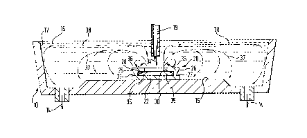
Figure 1 is a side cross-sectional view of a tundish
including an impact pad of the invention disposed on the floor of the
tundish;
Figure 2 is a top plan view of the impact pad of Figure 1,
which illustrates where the cross-section of Figure 1 is taken (along line
I to I);
Figure 3 is a cross-section along line III to III of Figure 2;
and
Figure 4 is an enlarged sectional view of a portion of the
impact pad of Figure 3.
In Figure 1, a conventional tundish 10 is shown and
includes an inner lining 12 and a pair of well blocks or outlets 14 to
allow molten metal (typically steel) from a bath 16 contained in the
tundish 10 to continuously exit the tundish 10 and enter moulds (not
shown) which form metal castings. As is also conventional, a ladle
shroud 18 or like tundish filling device, is positioned above the tundish
and continuously directs a stream of molten metal into the tundish
10. A tundish impact pad 20 constructed according to the present
invention is placed generally centrally on the floor 15 of the tundish 10.
As seen in Figures 1 to 4, the tundish impact pad 20 is
preferably rectangular in shape and is positioned with its longer sides
parallel to the longitudinal axis of the tundish. The pad includes a base

_ 5- _ 216255 ~ FS 1554
22 having a planar, horizontal, impact surface 24. The pad 20 further
includes an endless, annular outer sidewall 26, 40 having an inner wall
face surface 28. The impact pad 20 also has a top surface 32 parallel to
the impact surface 24 and connected to the sidewall 26, 40 and defining
a non-uniform opening 30 therein. By "non-uniform it is meant that
the opening 30 is not circular or square; rather it has a long dimension
30' (see Figure 2) and a short dimension 30" substantially
perpendicular to the long dimension 30'.
As seen in all of Figures 1 through 4, the interior face 28 of
the sidewall extends upwardly substantially at right angles to the
impact surface 24 around the entire periphery thereof. The continuous
nature of the inner surface 28 is perhaps seen most clearly in Figure 2,
being shown in dotted line therein.
As shown in Figures 3 and 4, the inner
sidewall surface 28, with impact surface 24 and
underside portion 42 of top surface 32, provides two
sharp corners 28A and 28B respectively, which corners
also extend continuously around the inside of the impact
pad.
As seen in Figure l, the outer sidewall 26 may be tapered
inwardly from the top surface 32 toward the base 22, defining ears 27
at opposite ends. The ears 27 facilitate connection of the impact pad 20
to the base or floor 15 of the tundish when certain types of tundishes
are utilised. Alternatively, the impact pad 20 may merely be mounted
in a conventional manner on the bottom of the tundish.
It is also noted that the bottom portion of the top surface 32
has annular portions 39, 42 (see Figure 3) thereof, which lie parallel to
the impact surface 24. This annular, overhang surface 42 facilitates

212 ~fi~ ~.
- 6 - FS 1554
proper directing of the molten steel during filling of the tundish 10.
Note that the long dimension 30' of the opening 30 is positioned aligned
with the long dimension of the tundish (the dimension between the
outlets 14, as seen in Figure 1), whereas the short dimension 30" of the
opening 30 is aligned with the short dimension of the tundish 10.
The outer sidewall portions 40, rather than being tapered
inwardly like the sidewall portions 26, preferably taper very slightly (e.g.
2 to 5°) outwardly, as seen in Figure 3. Alternatively, straight sides
may
be provided for both walls 26, 40 and straight sidewalls 26 may or may
not contain ears 27.
The refractory material of which the impact pad 20 is made
must be capable of withstanding continuous contact with molten steel
during the entire use cycle of the tundish 10. It must have adequate
refractoriness normally available from a standard medium-to-high
alumina monolithic refractory. For example, an alumina content in the
range of about 55 to 85% may be utilised. Where a basic refractory is
preferred because of the steel chemistry, typically an Mg0-based
monolithic refractory, with Mg0 in the range of about 58 to 93% is
preferred.
While it is preferred that the impact pad 20 be rectangular
in shape, as illustrated in Figures 1 through 4, other non-uniform
configurations can also be provided. For example, an oval impact pad
may be utilised, or another type of mufti-sided polygon configuration, as
long as there is an opening with a long dimension which is aligned with
the long dimension of the tundish 10 and a short dimension aligned
with the short dimension of the tundish 10.

- 7 - FS 1554
In use of the tundish pad 20 illustrated in Figure 1, molten
steel flowing in the path 34 from a location disposed above the pad 20
strikes the impact surface 24 and then moves radially outwardly as
illustrated by arrows 35. When the steel impacts the inner face 28 of
the sidewall, it is directed inwardly then upwardly, flowing as illustrated
at 36 in Figure l and ultimately being dispersed generally radially
outwardly as indicated by arrows 37, 38 in Figure 1. This minimises
turbulence on the surface of the bath 16 and helps direct slag and other
impurities away from the stream 34.
It is not essential that the corners shown in dotted line in
plan in Figure 2 be radiused as shown and the corners may, if desired,
be right-angled.
If desired, small corner fillets may be present in the right-
angle corners between the sidewall and the impact surface and/or the
top surface inner annular portion.

Representative Drawing
A single figure which represents the drawing illustrating the invention.
Administrative Status

2024-08-01:As part of the Next Generation Patents (NGP) transition, the Canadian Patents Database (CPD) now contains a more detailed Event History, which replicates the Event Log of our new back-office solution.

Please note that "Inactive:" events refers to events no longer in use in our new back-office solution.

For a clearer understanding of the status of the application/patent presented on this page, the site Disclaimer , as well as the definitions for Patent , Event History , Maintenance Fee  and Payment History  should be consulted.

Event History

Description Date
Inactive: Expired (new Act pat) 2015-11-09
Letter Sent 2010-07-14
Inactive: Office letter 2010-06-03
Grant by Issuance 2000-08-01
Inactive: Cover page published 2000-07-31
Pre-grant 2000-05-03
Inactive: Final fee received 2000-05-03
Inactive: Received pages at allowance 2000-05-01
Notice of Allowance is Issued 1999-12-13
Letter Sent 1999-12-13
Inactive: Approved for allowance (AFA) 1999-11-23
Amendment Received - Voluntary Amendment 1999-10-26
Inactive: S.30(2) Rules - Examiner requisition 1999-04-26
Inactive: Application prosecuted on TS as of Log entry date 1998-05-26
Inactive: Status info is complete as of Log entry date 1998-05-26
All Requirements for Examination Determined Compliant 1996-06-11
Request for Examination Requirements Determined Compliant 1996-06-11
Application Published (Open to Public Inspection) 1996-05-10

Abandonment History

There is no abandonment history.

Maintenance Fee

The last payment was received on 1999-10-19

Note : If the full payment has not been received on or before the date indicated, a further fee may be required which may be one of the following

  • the reinstatement fee;
  • the late payment fee; or
  • additional fee to reverse deemed expiry.

Patent fees are adjusted on the 1st of January every year. The amounts above are the current amounts if received by December 31 of the current year.
Please refer to the CIPO Patent Fees web page to see all current fee amounts.

Owners on Record

Note: Records showing the ownership history in alphabetical order.

Current Owners on Record
FOSECO INTERNATIONAL LIMITED
Past Owners on Record
DONALD RICHARD ZACHARIAS
Past Owners that do not appear in the "Owners on Record" listing will appear in other documentation within the application.
Documents

To view selected files, please enter reCAPTCHA code :


To view images, click a link in the Document Description column. To download the documents, select one or more checkboxes in the first column and then click the "Download Selected in PDF format (Zip Archive)" or the "Download Selected as Single PDF" button.

List of published and non-published patent-specific documents on the CPD .

If you have any difficulty accessing content, you can call the Client Service Centre at 1-866-997-1936 or send them an e-mail at CIPO Client Service Centre.


Document
Description 
Date
(yyyy-mm-dd) 
Number of pages   Size of Image (KB) 
Abstract 1996-03-25 1 27
Description 1996-03-25 7 290
Drawings 1996-03-25 2 39
Claims 1996-03-25 2 67
Claims 2000-04-30 2 68
Description 1996-08-26 7 288
Abstract 1996-08-26 1 28
Claims 1996-08-26 2 67
Representative drawing 1998-03-15 1 17
Representative drawing 2000-07-13 1 8
Claims 1999-10-25 2 67
Reminder of maintenance fee due 1997-07-09 1 111
Commissioner's Notice - Application Found Allowable 1999-12-12 1 164
Correspondence 1999-12-12 1 87
Correspondence 2000-04-30 2 52
Correspondence 2000-05-02 1 27
Correspondence 2010-06-02 1 17
Correspondence 2010-07-13 1 14
Correspondence 2010-06-09 2 42