Note: Descriptions are shown in the official language in which they were submitted.
WO 94/28978 PCT/US94/06249
'~ 2162991
t.....
STRETCH THERAPY APPARATUS FOR
PHYSICAL FITNESS, REHABILITATION
AND MEDICAL TREATMENT
DES CRIPTION
BACKGROUND OF THE INVENTION
is
Field of the Invention
The invention is generally related to an apparatus for safely
facilitating stretching exercises and rehabilitation. More particularly, the
2 o invention is directed to a stretch therapy apparatus that allows
stretching
of a wide variety of muscle groups without undue stress.
DeSCription of the Prior Art
2 s A physically fit person is defined by a combination of strength,
endurance, and flexibility. Many individuals concentrate on strength and
endurance by engaging in activities such as weight lifting and jogging,
but ignore the need to be flexible. However, it is widely recognized by
experts in the field that stretching prior to commencing an exercise
3 o regimen is of paramount importance to reduce the likelihood of exercise
related injuries. This is particularly true with regard to martial arts
regimens which demand optimum flexibility for swift, wide-ranged,
muscle group movements. FurtherTnore, lack of flexibility can lead to
problems with the lower back, etc., as a person ages.
3 5 Stretching is also an important part of any physical therapy
regimen practiced by patients undergoing physical rehabilitation following
WO 94/28978 PCT/US94I06249
r
2162991
an accident or illness, as well as patients seeking relief from common
ailments such as back pain. This type of therapy is commonly supervised
by a highly trained physical therapist, and may be conducted in a hospital
setting or at the patient's home. Paraplegic and quadriplegic patients must
also have their limbs stretched on a regular basis to avoid further medical
complications. For severely impaired patients, the therapist,must
maneuver the patient's limbs through a full range of motion while at the
same time being careful not to force or over stretch the muscles.
Traditionally, pre-exercise, post-exercise, as well as therapeutic
~ o stretching exercises are performed on the floor using a simple floor mat,
or by hanging from a bar. In a typical floor stretching exercise, a person
sits with his legs in a straddle position extended out in front of his torso.
The person bends his torso into the mat, thereby stretching his leg and
back muscles. To maximize the stretch, the person may extend his arms
~ s straight out over his head in a reaching fashion and the stretch is held
for
a short period of time. The stretching exercise may be assisted with the
help of a partner or therapist. For severely impaired patients, a therapist
must individually move each of the patient's limbs while the patient is on
a table or on the floor. In a hanging stretch exercise, the person hangs
2 o from a bar, such as, for example, in a chin-up preparation position, and
allows the weight of his or her own body to provide a downward stretch.
This method is particularly undesirable in a therapeutic environment since
the full body weight often provides many times more force than is
necessary or desired to accomplish the stretch, thus putting strain on the
2 s muscles. Additionally, a patient in therapy often lacks the strength in
their hands that is required to support their own body weight.
To date, few advances have been made in the design of machines
which facilitate stretching exercises. Typical examples can be found in
U.S. Patent 4,844,453 to Hestilow, U.S. Patent 5,108,090 to Reed,
3o U.S. Patent 4,445,684 to Ruff, and U.S. Patent 5,137,504 to Mangini.
It is important that stretching be carried out with smooth
continuous movements, rather than bouncy movements, in order to avoid
injuries during the stretching exercise itself. Ideally, the muscles should
be in a relaxed state to maximize the stretch and to avoid undue stress on
3 s the muscle, tendons, and skeleton. In addition, stretching a wide variety
of muscle groups will maximize the benefit to the user. Having a
machine designed to accomplish these objectives would be advantageous
WO 94/28978 PCT/US94/06249
2162991
3
since it would encourage healthy individuals to include stretching in their
fitness routine, and would aid in rehabilitation and medical treatment
regimens as well as reduce the cost of therapy.
s SUMMARY OF THE INVENTION
It is an object of this invention to provide a stretch therapy
apparatus useful for physical fitness, rehabilitation, and medical
treatment.
i o According to the invention, a stretch therapy apparatus provides
safe and effective stretching of a wide variety of muscle groups while the
user is in a relaxed sitting or prone orientation. The stretch therapy
apparatus includes a mechanism for stretching the back and arm muscles
without using the weight of the patient to apply the stretching force. The
back and arm muscles can be stretched with the user's torso oriented at
any inclination with respect to his or her legs. For example, the user is
permitted to stretch above his head as well as towards his or her feet. In
addition, the back and arni muscles can be stretched with the user's torso
being turned towards one or the other of his or her legs, thus stretching a
2 o different set of muscle groups than are stretched when the torso is
oriented in a forward direction. The stretch therapy apparatus also
includes a mechanism for stretching the user's thigh, calf, and foot
muscles. The user's legs are oriented on a pair of leg decks which can be
comfortably opened and closed to 180° or more. The leg decks can be
2 s oriented such that they project directly in front of the user's waist or
at an
incline above or below the user's waist. The leg decks can also be
adapted to reduce the pressure on the user's knees as they are opened and
closed, and can be folded to allow for hamstring stretching. Foot
supports are used to orient the user's toes relative to his ankle, thus
3 o providing calf stretching. All stretching mechanisms can be motorized,
controlled by hand crank, or be provided by stationary, incrementally
spaced ladder rungs. Indicia are provided for positive feedback to the
user, as well as to provide a trainer or therapist with stretching
assessment information.
PCT/US94/06249
WO 94/28978 216 2 9 91-
4
BRIEF DESCRIPTION OF THE DRAWINGS
The foregoing and other objects, aspects and advantages will be
better understood from the following detailed description of the preferred
s embodiments of the invention with reference to theJdrawings, in which:
Figure 1 is a plan view of a stretch therapy apparatus according to
a first embodiment of this invention;
Figure 2 is a side view of the stretch therapy apparatus of Figure
1;
i o Figure 3 is a detail side view of one embodiment of the hand
grip/pole assembly of the stretch therapy apparatus of Figure 1 where the
hand grip is moved up and down the pole by the user and is held in place
at a desired location on the pole using a ratchet mechanism to allow for
stretching;
~s Figure 3a is a detail front view of the embodiment of the hand
grip/pole assembly shown in Figure 3;
Figure 4 is a detail view of another embodiment of the hand
grip/pole assembly of the stretch therapy apparatus of Figure 1 where the
hand grip is moved up and down the pole by a drive mechanism;
2 o Figure 5 is a detail view of one embodiment of a pole orienting
mechanism together with the gear mechanism for moving the leg decks
for the stretch therapy apparatus of Figure 1;
Figure 6 is a detail view of the leg deck orientation indicia of the
stretch therapy apparatus of Figure 1;
2 s Figures 7a, 7b, and 7c are plan, isometric, and cross-sectional
views, respectively, of a leg deck structure for use in a stretch therapy
apparatus according to the first, second, third and sixth embodiments;
Figure 8 is a plan view of a stretch therapy apparatus similar to
that shown in Figure 1, but where ladder rungs are substituted for the
3 o moveable hand grip assembly;
Figure 9 is a plan view of a stretch therapy apparatus similar to
that shown in Figure 1, but where the pole is eliminated and ladder rungs
are positioned on each of the leg decks;
Figure 10 is a side view of a stretch therapy apparatus according
3 s to a second embodiment of this invention;
Figure 11 is a side view of a stretch therapy apparatus similar to
that shown in Figure 10, but where ladder rungs are substituted for the
WO 94/28978 216 2 991 PCT~S94/06249
S
moveable hand grip assembly;
Figure 12 is an isometric view of a stretch therapy apparatus
according to a third embodiment of this invention;
Figure 13 is an isometric view of the stretch therapy apparatus of
s Figure 12-with an attached motor drive configuration;
Figure 14 is an isometric view of a stretch therapy apparatus
similar to that shown in Figure 12, but where ladder rungs are substituted
for the moveable hand grip assembly;
Figure 15 is a side view of a stretch therapy apparatus according
1 o to a fourth embodiment of this invention;
Figure 16 is a side view of a stretch therapy apparatus similar to
that shown in Figure 15, but where ladder rungs are substituted for the
moveable hand grip assembly;
Figure 17 is a side view of a stretch therapy apparatus according
15 to a fifth embodiment of this invention;
Figure 18 is a side view of a stretch therapy apparatus according
to a sixth embodiment of this invention; and
Figure 19 is a side view of a stretch therapy apparatus similar to
that shown in Figure 18, but where the leg decks includes a lockable joint
2 o so that the leg deck can be shortened
DETAILED DESCRIPTION OF THE PREFERRED
EMBODIMENTS OF THE INVENTION
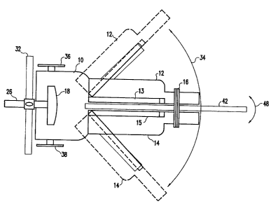
2 5 Figures 1 and 2 schematically show a stretch therapy apparatus
according to a first embodiment of this invention. The user sits on
platform 10 with his or her legs on leg decks 12 and 14 and hands on
handle bar 16. A seat back 18 is selectively adjustable to the user's size
by a pin/lock assembly 20 which is connected to seat support bar 22 and a
3 o pin/lock assembly 24 which is connected to spacing bar 26 as is indicated
by arrows 28 and 30. The seat back 18 may also be located to the left and
right of the platform 10 by movement along back locating bar 32.
Figure 1 shows that the leg decks 12 and 14 move along an arc 34
to stretch the leg muscles of the user. Hand cranks 36 and 38 located on
3 5 either side of the platform 10 are rotated by the user to cause a gear,
chain, pulley, or other suitable mechanism to move the leg decks along
the arcuate path. The leg decks 12 and 14 have side walls 13 and 15,
2162991
WO 94/28978 PCTIUS94/06249
6
respectively, designed to keep the legs on the leg decks 12 and 14 when
they are being opened and closed. The stretch therapy apparatus can be
constructed such that each of the hand cranks 36 and 38 can
simultaneously open leg decks 12 and 14 simultaneously in a symmetrical
fashion, or the hand crank 36 can open leg deck:f2 and the hand crank 38
can open leg deck 14 individually, or the hand cranks 36 and 38 can be
controlled to allow both simultaneous opening of the leg decks 12 and 14
and individual opening of the leg decks 12 and 14. A motor drive (not
shown) can be used in place of the hand cranks 36 and 38 to allow
1 o motorized opening and closing of the leg decks 12 and 14. The leg decks
12 and 14 may also include joint 40 that allows the deck to bend the foot
back towards the user to provide calf stretching.
Figures 1 and 2 also show that the stretch therapy apparatus
includes a stretching pole 42 which projects from the platform 10. The
~ 5 stretching pole is used to stretch the users back and arrn muscles. Figure
2 shows that the stretching pole 42 can be selectively locked into any
angular position along arrow 44 with respect to the platform 10 by
orienting and locking means 46. Figure 1 shows that the stretching pole
42 can also be centrally oriented or at an angular position towards either
2 0 of the user's legs as is indicated by arrow 48. The user will select an
angular position for the stretching pole 42 along arrow 44 and an angular
position for the stretching pole 42 along arrow 48, and then will lock the
pole 42 into position using locking means 46. In this way, the user can
select the degree to which he or she flexes at the waist and the degree to
2 s which he or she rotates at the waist
In operation, the user grasps handle bar 16 after the stretching
pole 42 is correctly positioned and moves the handle bar 16 away from
his or her body along the length of the pole 42. After the arms and back
muscles are fully extended, the handle bar 16 is locked into position so
3 o that the back and arm muscles can be stretched. The resulting stretch is
far safer and easier than hanging from a chin-up bar since the user's full
body weight is not being used to apply the stretching force. As described
below in connection with Figure 4, a motor drive mechanism may also be
employed to move the handle bar 16 up and down the stretching pole 42.
3 5 Figure 2 also shows that the handle bar 16 can be pivotally connected to
the stretching pole 42 to allow a more ergonomic sitting arrangement
when stretching. In addition, as shown in Figure 13, the pole 42 can
WO 94/28978 PCT/US94/06249
7
telescoping such that segments of the pole retract within one another. As
will be discussed a fra, means, such as a motor, hydraulic pump or other
mechanism, can be provided for controlled in and out movement of the
segments of the pole 42. By using the stretching pole 42 in combination
s with leg decks 12 and 14, a wide variety of muscle groups can be
stretched with the stretch therapy apparatus. For example, the user will
stretch different muscle groups by spreading his or her legs and stretching
forward from the waist, than if the user stretched to the left or right with
his legs spread.
While Figures 1 and 2 show the stretching pole 42 extending from
the platform 10, it should be understood that the pole 42 can extend from
the support structure of the stretch therapy apparatus or be free standing.
As shown in Figure 2, the platform 10 can be supported by one or
more legs 11. These legs can be fixed or can include means (not shown),
i s such as a motor, hydraulic pump or other mechanism, for adjusting the
tilt of the stretching apparatus. The ability to adjust the angle of the
stretching apparatus can increase the stretching effect for the user.
Figures 3 and 4 illustrate alternative mechanisms for moving the
handle bar 16 along the length of the stretching pole 42. In Figures 3 and
2 0 3a, a slide 52 with wheels 54 or other means moves up the pole 42 as the
user extends his or her arms. Once the arms are fully extended, the
handle bar 16 is held in position using a ratchet assembly 56 that
interlocks with teeth 58. After stretching, the user will let go of the
handle bar 16, and pull on the handle of the ratchet assembly 56 so that
2 s the handle bar 16 may be moved back down the pole towards the user.
Figure 3a provides a detailed front view of the stretching pole 42 which
can be configured to include visual indicia of the location of the handle
bar 16 on the stretching pole 42. The visual indicia can be used by the
user or a therapist to monitor the progress of the user. While Figure 3
3 o shows a ratchet mechanism for locking the handle bar 16 in position on
the stretching pole 42, it should be understood that several other
mechanisms can be used within the practice of the invention. In Figure 4,
a screw drive 60 is positioned inside the stretching pole 42. The user will
depress a button 62 on the handle bar 16 which will direct a motor (not
3 s shown) to rotate the screw 60. The slide assembly 64 will move up the
length of the sliding pole 42 as long as the button 62 is depressed and the
handle bar 16 will be held in position once the user's arms are fully
PCT/US94/06249
WO 94/28978 216 2 9 91. _
8
extended to allow a stretching exercise. After stretching for a period of
time, the slide assembly 64 will be moved to a new location on the pole
under motor control. Alternatively, the slide assembly 64 will be
selectively disengageable from the screw 60 to move it to a new location
s on the pole 42. While Figure 4 shows a screw drive mechanism for
moving and locking the handle bar 16 in position on the stretching pole
42, it should be understood that other mechanisms such as chains,
pulleys, etc., can be used to achieve motorized positioning of the handle
bar 16 within the practice of this invention.
1 o Figure 5 shows a gear mechanism 66 positioned under the
platform 10 can be used to drive the leg decks 12 and 14 apart
Preferably, the gear mechanism allows for very fine adjustments to the
angular orientation of the leg decks. With simultaneous reference to
Figures 1 and 5, it would advantageous to have the hand cranks 36 and
38 open the leg decks 12 and 14 approximately one half to two degrees
per full revolution. If the leg decks were allowed to open five degrees or
more per revolution, the user would not be able to widen his legs as
accurately or as safely. As the user becomes more proficient, fine
incremental increases in the angular degree of leg stretching will become
2 o more important to him or her. It should be understood that other
mechanisms can be used in place of gears 66; however, gears 66 are
preferred since they are more readily adapted to achieve precise control of
the degree of leg deck opening.
Figure 6 shows indicia 68 on the platform 10 that provides the
2 s user with positive feedback on the degree of leg opening achieved. The
indicia 68 may also be used by an attending trainer or therapist to track the
progress of the user. Figure 6 also shows a pin/lock mechanism used for
orienting the stretching pole 42 at a desired angular orientation with
respect to platform 10. Specifically, the pole 42 will be moved to a
3 o desired location and the pin 69 will be inserted into opening 70 to lock
the
pole in position.
With reference back to Figure 5, it can be seen that the pole 42
orienting and locking assembly 46 is also provided with indicia 72 that
allows the user to precisely select the angle of the pole 42 relative to the
3 5 platform 10. A pin/lock mechanism 74 acts in conjunction with the
locking assembly 46 to maintain the pole 42 in the selected angular
orientation. Positioning the pin/lock mechanism 74 directly in front of the
WO 94/28978 PCT/US94/06249
9
user allows for easier operation; however, other configurations can be
used within the practice of this invention. While a pin/lock mechanism 74
is shown in Figure 5, it should be understood that many other
mechanisms can be employed
s Figures 7a-7c illustrate an enhancement to the leg decks used in
the stretch therapy apparatus that will reduce undue stress on the knees of
the user. Figure 7a shows 80 and 82 each have a bend region 84. In the
preferred embodiment, the bend region 84 is positioned approximately 6
to 12 inches along the leg decks 80 or 82, starting from the end closest to
o the platform 10. Furthermore, it is preferred that the inner angle of the
bend region be in the range of approximately 120 degrees to 180 degrees
and it is most preferred that the angle is approximately 150 degrees.
Figures 7b and 7c show that the leg decks 80 or 82 are secured to sliding
tubular connectors 86 by risers 88. The tubular connectors 86 travel on
1 s poles 90 associated with each leg deck 80 or 82. As the legs are
separated by rotation of the crank 92, the leg decks 80 and 82 are
permitted to slide along the poles 90 a short distance. The sliding motion
of the leg decks 80 and 82 along with the bend region 84 reduce the
amount of stress on the user's knees as the leg decks 80 and 82 are
2 0 opened and closed compared to leg decks which do not slide and do not
have a bend region.
Figure 8 shows a stretch therapy apparatus similar to that shown
in Figure 1. Therefore, like elements have been indicated with the same
numbers on both Figures. In Figure 8, the stretching pole 96 has a
2 s plurality of ladder rung projections 98 along its length. For all other
purposes, the stretch therapy apparatus of Figure 8 works in the same
fashion as that described in Figure 1 (e.g., the leg decks 12 and 14 open
and close, and the stretching pole 96 can be oriented in any selected
vertical inclination and at any selected horizontal angle). In operation, the
3 o user will orient the stretching pole 96 as described above. Then, in order
to perform a stretching exercise, he or she will reach for a pair of the
ladder rung projections 98. Once the ladder rung projections 98 are
grasped, the user will hold the stretch for a period of time. The user can
track his or her progress by monitoring the ladder rung projection he or
3 s she has grasped for the stretch.
Figure 9 shows a stretch therapy apparatus where the stretching
pole has been eliminated. However, stretching of the user's back and
WO 94/28978 2 i b 2 9 ~ i PCTIUS94/06249
arms is still accomplished using ladder rung projections 100 positioned
along the length of the leg decks 12 and 14. In the design shown in
Figure 9, the user will open the leg decks 12 and 14 to the desired angle,
and will then reach for a ladder rung on one or the other leg deck. After
s grasping the ladder rung, the user will hold the str~tch'for a period of
time. While not shown in Figure 9, it should be understood that a sliding
handle bar mechanism Like that described in conjunction with Figures 1-4
could be built into each leg deck 12 and 14 in place of the ladder rungs
100.
i o Figure 10 shows a second embodiment of the stretch therapy
apparatus where the stretching pole 110 is positioned above the user's
seated position. The leg decks 12 and 14 operate in the same manner as
discussed above in conjunction with Figures 1 and 2; therefore, the same
numbering scheme for like elements has been used. The stretching pole
i s 110 is connected to support pole 112 by a pole orienting mechanism 114.
The pole orienting mechanism 114 allows the stretching pole 110 to pivot
vertically along arc 116 and to rotate about the support pole 112 along
arcs 118 and 120. The height of the stretching pole 110 above the
platform 10 is adjustable as indicated by arrow 122. In operation, the
2 o user orients the stretching pole 110 to a selected vertical angle and
horizontal angle (e.g., the pole 120 is oriented in three dimensional space
in the same way as described above in conjunction with Figures 1 and 2)
and then locks the pole into position using locking means 126. The user
then grasps the handle bar 128 and moves it along the stretching pole 110
2 s as indicated by arrow 130 until his or her amts are fully extended. A
ratchet or other suitable mechanism associated with the sliding member
132 will hold the handle bar 126 in position as the user performs his or
her stretching exercise. An advantage of the stretch therapy apparatus of
Figure 10 is that it allows the user to perform a stretch directly above his
3 0 or her head while in the seated position on platform 10.
Figure 11 shows a stretch therapy apparatus identical to that
shown in Figure 10, except for the stretching pole I36; hence, like
numerals have been used to indicate like elements. The stretching pole
136 has been modified by using a plurality of ladder rung projections I38
3 s instead of a sliding handle bar. As described above, the user will orient
the stretching pole 136, then grasp a pair of the ladder rung projections
138 to perform a stretching exercise.
WO 94/28978 ~ 16 2 9 ~ ~ PCT~S94/06249
11
Figure 12 shows a third embodiment of the stretch therapy
apparatus. As discussed in conjunction with the second embodiment
shown in Figures 10 and 11, the leg decks 12 and 14 operate in the same
manner as described above in conjunction with the embodiment of Figure
s 1; therefore; dike numerals have been used to indicate like elements. The
chief difference in the stretching apparatus shown in Figure 12 is that the
stretching pole 140 is separate from the platform 10. The stretching pole
140 is connected to a support pole 142 that is moveable around a track
144 that encircles the machine. The height of the stretching pole 140 is
~ o adjustable as indicated by arrow 146 and can be set by lock mechanism
148. The vertical angular orientation of the stretching pole 140 is also
adjustable as indicated by arrow 150 and can be set by lock mechanism
152. In operation, the user sets the height and orientation of the
stretching pole 140, and the location of the pole is then adjusted by
15 movement within the track 14.4 as indicated by arrows 154 and 156. An
advantage of the configuration shown in Figure 12 is that the user will be
able to rotate about his or her torso to a greater degree while performing
stretches than is possible with the first embodiment of the stretch therapy
apparatus. For example, while the user's legs are spread he or she can
2 o rotate his or her torso to grasp handle bar 157 on stretching pole 140
when the stretching pole 140 and support pole are located at points I58 or
160 in the track 14.4.. As discussed above in connection with the previous
embodiments, the user grasps the handle bar 157 and moves it along the
stretching pole 140 until his or her arms are fully extended. A ratchet or
2 s other suitable mechanism will hold the handle bar 157 in position as the
user performs his or her stretching exercise.
Figure 13 shows a stretch therapy apparatus identical to that
shown in Figure 12, except for the stretching pole 166; hence, like
numerals have been used to indicate like elements. The stretching pole
3 0 166 has been modified to be of telescoping construction. The user will
grasp the handle bar 168 after the stretching pole 160 is oriented by
adjusting the height on support pole 142 and vertical inclination 150 using
lock mechanism 152. The user will then fully extend his or her arms so
that segments of the telescoping stretching pole 160 retract within one
3 5 another. A means 170, which can be a motor, hydraulic pump, or other
mechanism, can be provided to allow controlled movement of the
segments in and out in the telescoping stretching pole 162. After the
WO 94/28978 PCT/US94I06249
12
user's arms are fully extended, the telescoping stretching pole 166 is
locked so that the user can perforrn a stretching exercise for a short period
of time.
Figure 14 shows a stretch therapy apparatus identical to that
shown in Figure 12, except for the stretching.pol~e 172; hence, like
numerals have been used to indicate like elements. The stretching pole
172 has been modified by using a plurality of ladder rung projections 174
instead of a sliding handle bar. As described above, the user will orient
the stretching pole 172, then grasp a pair of the ladder rung projections
i o 174 to perform a stretching exercise.
Figure 15 shows a fourth embodiment of the stretch therapy
apparatus. A user is seated on chair 176. The chair 176 swivels about
base 178 as indicated by arrows 180 and can be selectively locked into
position using a pin/lock mechanism 182 that can comfortably be operated
i s by the user while in the chair 176. The user's feet are positioned on foot
pedestal 184. The height of the foot pedestal 184 can be adjusted as
indicated by arrow 186 using a pin/lock mechanism 188 in combination
with vertical bar 190. The distance the foot pedestal 184 is positioned
from the chair 176 is adjustable as indicated by arrow 192 and can be set
2 o using a pin/lock mechanism 194 on horizontal bar 196. The foot pedestal
176 can be equipped with a tilting mechanism to tilt the angle of
inclination relative to vertical bar 190 so that user's calf and foot muscles
are stretched as indicated by arrow 185. The angle of the seat back 198 is
adjustable as indicated by arrow 200 using a pin/lock or other suitable
2 s mechanism 202. A stretching pole 204 is connected to a support pole 206
positioned in base 208. The height of the stretching pole 204 on support
pole 206 can be adjusted using a pin/lock mechanism 210, or may be
adjusted using a motor drive 212 or other suitable mechanism. The
vertical angle of the stretching pole 204 is adjustable as indicated by
3 o arrow 214 using a pin/lock or other suitable mechanism 216. As
discussed above, the user will grasp handle bar 218 after he or she has
oriented the stretching pole 204 and the seat 176, and will slide the handle
bar 218 on stretching pole 204 until his or her arms are fully extended. A
ratchet mechanism or the like will then hold the handle bar 218 in position
3 s until the user has completed the stretching exercise. The stretch therapy
apparatus of Figure 15 has the advantage of being relatively inexpensive
to construct, but still providing an improved arm and back muscle
WO 94/28978 PCT/US94I06249
21 b299,1
13
stretching machine that does not put undue force on the muscles and still
allows the user with a full range of movement about his or her torso when
performing the stretches.
Figure 16 shows a stretch therapy apparatus identical to that
s shown in Figure: l5, except for the stretching pole 220; hence, Iike
numerals have been used to indicate Iike elements. The stretching pole
220 has been modified by using a plurality of ladder rung projections
222 instead of a sliding handle bar. As described above, the user will
orient the stretching pole 220 and the seat 176, then grasp a pair of the
l o ladder rung projections 222 to perform a stretching exercise.
Figure 17 shows a fifth embodiment of the stretch therapy
apparatus. A user sits on platform 230 with his or her feet on pedestal
232. The height of the platform 230 and pedestal 232 are adjustable
using pin/lock or other suitable mechanisms that operate in conjunction
is with support bars 234 and 236, respectively. A seat back 238 is
positioned behind the user using both vertical and horizontal adjustments
as indicated by arrows 240 and 242, respectively, on vertical support 244
and horizontal support 246. Pin/lock or other suitable mechanisms can be
used on the vertical support 244 and horizontal support 246. A stretching
2 o pole 248 positioned in front of the user extends from support frame 250.
Preferably, the position of the stretching pole 248 on the support frame
250 is adjustable using a pin/lock or other suitable mechanism 252, and
the angular orientation of the stretching pole 248 can be adjusted using a
pin/lock or other suitable mechanism 254 that operates in conjunction
2s with a stretching pole orienting mechanism 256. Similar to the method
described above, a user will orient the stretching pole 248, and then grasp
handle bar 258 and slide it along stretching pole 248 until his or her arms
are fully extended. The handle bar 258 will then be held in position to
allow the user to perform a stretching exercise. The handle bar 258 may
3 o be provided with two different grip sites 260 and 262 to provide the
stretch therapy apparatus enhanced flexibility. As discussed above with
the previous embodiments, ladder rungs (not shown) may be substituted
for sliding handle bar 258.
Figure 18 shows a sixth embodiment of the stretch therapy
3 s apparatus. The user is positioned on platform 270 with the seat back 272
up or down. A pin/lock or other suitable mechanism 274 allows the seat
back 272 to be positioned at any desired inclination. A separate headrest
WO 94/28978 PCTIUS94I06249
21 b299 ~
14
294 can be provided with the seat back 272 for the comfort of the user.
As indicated by arrow 292, the headrest 294 can be adjusted relative to
the seat back 272 to accommodate the user. The user positions his or her
legs in leg decks 276 that are similar in construction to those shown in
s Figures 1 and 7. Hand crank 278 or a motorized mechanism is used to
raise and lower the leg decks 276 for stretching of the hamstring and
gluteus maximus muscles. A major advantage of the sixth embodiment is
that the angle of inclination of the leg decks 276 can be adjusted relative to
the user as is indicated by arrows 280, 282, and 284. In operation, the
~o Ieg decks 276 are pivoted using a pivotllock mechanism 288 or other
suitable mechanism to a desired angular orientation and held in that
orientation, and the seat back 272 is positioned at a desired angular
orientation. Arrow 290 indicates that the seat back 272 can also be
moved axially relative to the leg decks 276 to accommodate the user.
1 s Once the leg decks 276 and seat back 272 are in position, the user
operated the hand crank 278 to raise and lower the leg decks to perform a
stretching exercise.
Figure 19 shows a stretch therapy apparatus similar to that shown
in Figure 18, except for the leg decks 276, therefore, similar numerals
2 o have been used to indicate Iike elements. The leg decks 276 have been
modified to include two pieces 296 and 298 which are connected by a
pivot/lock mechanism 300. The user can thereby lock the leg decks 276
in angled configurations to allow for stretching of the hamstring and
gluteus maximus muscles without full extension of the user's legs.
2 s While the invention has been described in terms of its preferred
embodiments, those skilled in the art will recognize that the invention can
be practiced with modification within the spirit and scope of the appended
claims: