Note: Descriptions are shown in the official language in which they were submitted.
216301
METHOD FOR SPATIALLY CONTROLLING THE PERIOD AND AMPLITUDE
OF BRAGG FILTERS
FIELD OF THE INVENTION
The invention relates to a method for spatially controlling the period and
amplitude
of Bragg gratings in an optical medium written with electromagnetic radiation.
DESCRIPTION OF THE PRIOR ART
It is known in the art that UV light can be used transversally to permanently
increase
the refractive index of an optical fiber. Further, it is known that by
illuminating an optical
fiber with a UV-light interference pattern, a periodic index change is
produced in the core of
the optical fiber, and thus a strongly selective wavelength reflection filter
is obtained.
By using techniques such as interferometry, transverse holography or phase
masking
to obtain an interference pattern of the UV-light, a Bragg grating is
impressed in the core of
the optical fiber.
U.S. Patent 5,327,515 (Anderson et al.) describes a method for processing
optical
media in order to form gratings within them. The gratings are impressed by a
single actinic
beam through a phase mask having a given period. The beam may be at an angle 8
with
respect to normal incidence (z-axis) on the phase mask. Furthermore, the
optical fiber itself
may be at an angle in the x- and y- axes. However, the author does not discuss
the effects of
using angles other than 0, when interference of orders ~1 are used to produce
the periodic
index change in the core of the fiber.
This patent suggests that the amplitude of the fiber grating may be adjusted
by moving
the beam along the axis of the fiber. The disadvantage with this method is
that the phase may
drill; slightly due to the movement of the beam, resulting in an uneven
filter.
Reference may also be made to the following patents and articles: US 4,474,427
(Hill
et al.); US 4,725,110 (Glenn et al.); US 4,807,950 (Glenn et al.); US
5,363,239 (Mizrahi et
al.); US 5,351,321 (Snitzer et al.); US 5,367,588 (Hill et al.); US 5,384,884
(Kashyap et al.);
US 5,388,173 (Glenn); US 5,420,948 (Byron); HILL et al., "Photosensitivity in
Optical Fiber
2163061
2
Waveguides: Application to Reflection Filter Fabrication", Appl. Phys. Lett.,
Vol. 32, No. 10,
647-649, 15 May 1978; MELTZ et crl., "Formation of Bragg Gratings in Optical
Fibers by
Transverse Holographic Method", Optics Letters, Vol. 14, No. 15, 823-825, 1
August 1989;
HILL et al., "Bragg Gratings Fabricated in Monomode Photosensitive Optical
Fiber by UV
Exposure Through a Phase Mask", Appl. Phys. Lett., Vol. 62, No. 10, 1035-1037,
8 March
1993; ANDERSON et al., "Production of In-Fibre gratings Using a Diffractive
Optical
Element", Electronics Letters, Vol. 29, No. 6, 566-568, 18 March 1993; KASHYAP
et al.,
"Wavelength Flattened Saturated Erbium Amplifier Using Multiple Side-Tap Bragg
Gratings", Electronics Letters, Vol. 29, No. 11, 1025-1026, 27 May 1993;
PROHASKA et al.,
"Magnification of Mask fabricated Fibre Bragg Gratings", Electronics Letters,
Vol. 29, No.
18, 1614-1615, 2 September 1993, MARTIN et al., "Novel Writing Technique of
Long and
Highly Reflective In-Fibre Gratings", Electronics Letters, Vol. 30, No. 10,
811-812, 12 May
1994; FARRIES et al., "Very Broad Reflection Bandwidth (44 nm) Chirped Fibre
Gratings
and Narrow Bandpass Filters Produced by the Use of an Amplitude Mask",
Electronics
L
Letters, Vol. 30, No. 1l, 891-892, 26 May 1994; KASHYAP et al., "Novel Method
of
Producing All Fibre Photoinduced Chirped Gratings", Electronics Letters, Vol.
30, No. 12,
996-998, 9 June 1994; PAINCHAUD et al., "Chirped Fibre Gratings Produced by
Tilting the
Fibre", Electronics Letters, Vol. 31, No. 3, 171-172, 2 February 1995; and
COLE et al.,
"Moving Fibre/Phase Mask-Scanning Beam Technique for Enhanced Flexibility in
Producing
Fibre Gratings with Uniform Phase Mask", Electronics Letters, Vol. 31, No. 17,
1488-1490,
17 August 1995.
SUMMARY OF THE 1NVENT10N
A first object of the invention is to provide an improved method for spatially
controlling the period and amplitude of Bragg filters in an optical medium
which is simpler,
more flexible and more suitable for mass production.
In accordance with the invention, this first object is achieved by an improved
method
for spatially controlling the period and amplitude of Bragg filters in a
optical medium having
a longitudinal axis that is sensitive to at least some wavelength of
electromagnetic radiation
comprising the steps of
- providing an optical phase mask of period A;
CA 02163061 2001-05-10
3
- laying the phase mask close to the optical
medium;
- impinging a single beam of electromagnetic
radiation of wavelength ~, on said phase mask such that the
radiation is diffracted, thereby resulting in an
interference pattern having a period P that is impinged
into the optical medium;
- said single beam of electromagnetic radiation
impinging said phase mask at an incidence angle cp with
respect to normal incidence on the phase mask; and
- said phase mask being oriented at an angle a with
respect to said longitudinal axis of said optical medium,
said angle a being different from zero; and
- selecting said incidence angle cp to produce a
preselected value for P according to the following
relationship:
p = n (1 + n sin 8 sin ~i tan a)-1
2 cos a
where 8 = (61 + 62)/2
a=~_ez+e
6, = arcsin(~,/A + since) - cp
82 = arcsin(~,/1~ - since) + cp
wherein said incidence angle cp is equal to said angle a,
such that said longitudinal axis of said optical medium is
perpendicular to said single beam of electromagnetic
radiation.
CA 02163061 2001-05-10
3a
It is a second object of the invention to provide an
improved method for producing linearly-chirped Bragg
gratings in an optical.
In accordance with the invention, this second object
is achieved to a method for impinging gratings in an
optical medium that is sensitive to at least some
wavelengths of electromagnetic radiation, said medium
having a longitudinal axis, said method comprising the
steps of
- providing an optical phase mask of period 1~;
- laying said phase mask close to said optical
medium;
- impinging a single beam of electromagnetic
radiation of wavelength ~, on said phase mask such that
said radiation is diffracted to produce an interference
pattern having a period P in said optical medium;
- inserting a lens of focal length f placed at a
distance d from said phase mask to produce a distribution
of incidence angles on said phase mask,
- said phase mask being oriented at an angle a with
respect to said longitudinal axis of said optical medium,
said angle a being different from zero;
whereby said period of said interference pattern
varies linearly along said longitudinal axis of said
optical medium according to the following relationship:
P~x~= A 1 _ 2 x a ,~
2 f-d
3 0 where t~ = 1 + 1 1 - ~,z -'%
2 2 A2
CA 02163061 2001-05-10
3b
where x is the longitudinal position.
It is a third object of the invention to provide an
improved method for producing linearly-chirped Bragg
gratings in an optical medium where the magnitude of the
index change varies as a function of the longitudinal axis
of the optical medium.
In accordance with the invention, this third object is
achieved to a method for impinging gratings in an optical
medium that is sensitive to at least some wavelengths of
electromagnetic radiation, said medium having a longitu-
dinal axis, said method comprising the steps of:
- providing an optical phase mask of period ~;
- laying said phase mask close to said optical
medium;
- impinging a single beam of electromagnetic
radiation wavelength ~ on said phase mask such that said
radiation is diffracted to produce an interference pattern
having a period P in said optical medium;
- inserting a lens of focal length f placed at a
distance d from said phase mask to produce a distribution
of incidence angles on said phase mask such that said
period of said interference pattern varies linearly along
said longitudinal axis;
- inserting a slit between said single beam and
said lens; and
- sliding said slit in a direction perpendicular to
said single beam at a variable velocity;
wherein:
said single beam of electromagnetic radiation is
impinged at an incidence angle ~ with respect to normal
incidence on said phase mask;
CA 02163061 2001-05-10
3c
said phase mask being oriented at an angle a with
respect to said longitudinal axis of said optical medium;
and
said incidence angle cp is equal to said angle a and is
different from zero;
whereby said period P of said interference pattern can
be altered by changing said incidence angle ~p or said angle
a according to the following relationship:
- 2xa ,~
2 f-d
-'~a
where r~ = 1 + 1 1
2 2 Az
where x is the longitudinal position.
BRIEF DESCRIPTION OF THE DRAWINGS
The present invention and its advantages will be more
easily understood after the reading of the following non-
restrictive description of the preferred embodiments
thereof, made with reference to the following drawings
where:
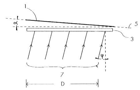
Figure 1 is a schematic representation of the first
preferred embodiment of the invention;
Figure 2 is a schematic representation of the second
preferred embodiment of the
2163061
4
invention;
Figure 3 is a schematic representation of the third preferred embodiment of
the
mventoon;
Figure 4 shows the diffraction effciency as a function of the angle of
incidence for 0
and ~l orders for TE and TM polarizations, for a binary phase mask having a
period of 1.06
microns and a duty cycle of 0.5;
Figure 5 is a schematic representation of a blazed grating;
Figure 6 shows the reflection spectrum of various gratings of different Bragg
wavelength obtained using the first preferred embodiment of the invention;
Figure 7 show the reflection spectrum of a 17-nm bandwidth chirped fiber
grating
obtained using the second preferred embodiment of the invention; and
Figure 8 shows a fitted (solid line) and target (broken line) transmission
spectrum of
a Bragg grating obtained using the third preferred embodiment of the
invention.
DESCR1PT10N OF PREFERRED EMBOD1MENTS OF THE INVENT10N
The following description will be made with reference to glass optical fibers,
but it
should be understood that it is applicable to any optical medium that is
sensitive to at least
some wavelength of electromagnetic radiation.
In a first preferred embodiment shown in Figure l, a phase mask 3 of period A
is laid
close to an optical fiber 1 having a longitudinal axis 5. A single beam 7 of
electromagnetic
radiation, preferably ultra-violet light (hereinafter denoted by "UV"), having
a wavelength
~, and a width D, is directed on the phase mask 3 such that the radiation is
diffracted by the
phase mask 3. This results in an interference pattern (not shown) having a
period P being
impinged into the optical fiber 1.
When the fiber 1 is not parallel to the phase mask 3 but rather forms a tilt
angle a with
the phase mask 3 and the UV beam 7 is incident on the phase mask 3 at an
incidence angle
cp, the period P of the interference pattern along the axis 5 of the optical
fiber 1 is given by
the following expression (assuming that orders other than ~1 are negligible):
[ 1 ] p = 2 g a (I + ~ sin 9 sin ~i tan a)-1
2163061
where 8 = (6, + 6z)/2
~_~_ez+e
6, = arcsin(~,/A + since) - cp
62 = arcsin(~,/A - since) + cp
For small angles a and cp, equation [1] reduces to:
-~/a
[2] p - A 1 + az - a ~ 1 - ~z
2 2 AZ
Thus, for a tilt angle a different from 0, the period P of the interference
pattern can be
modified by changing the incidence angle cp of the UV beam 7 or the angle a.
This result can
be used to precisely control the period of periodic Bragg gratings. Preferably
for this purpose,
the tilt angle a is equal to the incidence angle cp, by having the beam 7
preferably directed
toward the fiber 1 at normal incidence with respect to the axis 5 of the fiber
1. Thus, the
optical fiber 1 is fixed with respect to the UV beam 7 and only the phase mask
3 is rotated in
order to control the period P of the grating. From equation [2], valid for
small angles, the
relationship between the wavelength at which the optical fiber 1 reflects (the
Bragg
wavelength, denoted hereinafter by ~,~) and the incidence angle cp is given
by:
[3] RB = n A (1- Y ~Pz /2)
where 'y = 2( 1 - ~,2/Az) ''' - 1
and n is the core index of the fiber 1,
so that by adjusting the incidence angle cp, the Bragg wavelength ~,B can be
controlled.
Since the method involves the use of a phase mask 3 out of normal incidence,
the
dependence of the diffraction efficiencies on the angle of incidence cp must
be considered.
As can be seen in Figure 4, the diffraction efFciencies of 0 and ~l orders as
a function of the
incidence angle cp for both TE and TM polarizations remain almost identical
for incidence
angles cp smaller than 20°. Thus, the method must be limited to
incidence angles cp between
0° and 2CP , which allows for a very good flexibility. Curves of Figure
4 were claculated
2163061
6
considering a typical binary phase mask having a period of 1.OG microns and a
duty cycle of
0.5.
Furthermore, the method also involves irradiation of the fiber 1 by an
interference
pattern with the fringes tilted at a certain angle with respect to the fiber
axis 5, resulting in a
blazed angle ~, shown in Figure 5, given by:
[4) 8 = ~ _ a~
where (3 is defined above.
It is important that the blazed angle 8 remains small in order to avoid a
coupling of the
propagating light outside of the fiber 1. The condition that must be met is:
[5) b < 1 arcsin NA.
2 n
k.
where N.A. is the numerical aperture and n is the core index of the fiber 1.
For example, in a typical telecommunications fiber, n = 1.45 and N.A. = 0.12,
so that
8 must remain below 2.4°.
According to the first preferred embodiment of the invention, the period P of
the
grating is adjusted only by rotating the phase mask 3, so that a = cp. Since
~3 is approximately
equal to cp, the condition a = cp leads to an almost unblazed grating. More
precisely, for cp =
20°, the blazed angle 8 is 0.8°. For example, for a grating made
in the 1550 nm region and an
incidence angle cp between 0° and 2(p, which is sufficient for most
applications, the blazed
angle 8 does not exceed 0.8°.
Experimental tests have shown that the Bragg wavelength ~.B may be tuned with
this
method. Figure 6 presents the reflection spectrum of a fiber 1 in which nine
gratings of
different periods were written side by side by rotating the phase mask 3. As
can be seen from
Figure G, the result shows a tuning of the Bragg wavelength ~,s by 22 nm over
the 10° range
of the incidence angle cp. This is in accordance with the theoretical
prediction of 25 nm from
equation [3].
Thus, the Bragg wavelength ~,n can be precisely tuned by simply rotating the
phase
mask 3 in a simple manner which is appropriate for mass production.
2163061
In a second preferred embodiment of the invention shown in Figure 2, the above-
mentioned method comprises an additional step, where a lens 9, having a focal
length f and
placed at a distance d from the phase mask 3 is used to generate a
distribution of incidence
angles cp on the phase mask 3 and produce a linearly-chirped Bragg grating, as
shown in
Figure 2.
Using the lens 9 produces an interference pattern for which the period P(x)
varies
linearly along the axis 5 of the fiber 1, given by the following expression:
[6] P(x)= 2 1 - ~ x a t~
2 -'/a
where ~ = 1 + 1 1 -
2 2 Az
w
Consequently, the grating reflects light of dif~'erent wavelengths at
different grating portions
following:
[7] ~.H(x) = 2 n P(x)
For a grating of length L, the spectral broadening associated with the chirp
is then given by:
] 0~ = 2 n AL a rI = 2 n AD a ~
In this second preferred embodiment, the lens 9 is used to generate a
distribution of incidence
angles cp on the phase mask 3, resulting in a distribution of blazed angles 8.
In order to avoid
any coupling of the propagating light outside the fiber 1, the following
condition must be
satisfied:
2163061
g
[9] arctan D < 1 arcsin NA.
2f 2 n
For example, for a standard telecommunications fiber where n = 1.45, N.A. =
0.12, using a UV
beam 7 of width D = 10 mm, the smallest focal length f of the lens 9 that can
be used is 120
mm. Using that focal length in combination with a tilt angle a of 1°
leads to a grating having
a bandwidth ~~, of 4.5 nm.
In experimental tests, a divergent lens 9 having a focal length f of 50 mm was
placed
at a distance d of 20 mm from the phase mask 3 and a fiber 1 having a large
numerical
aperture was tilted at an angle a of 1.6°. A 14 mm-long Bragg filter
was obtained, having the
reflection spectrum shown in Figure 7. The bandwidth 0~, of this chirped
grating is 17 nm,
which is in accordance with the theoretical prediction of 17.3 nm from
equations [6] and [7].
This method fo' obtaining a chirped grating is flexible and can be used for
mass
production.
In a third preferred embodiment of the invention shown in Figure 3, the method
described above comprises the additional step of inserting a moving slit 11
between the UV
beam 7 and the lens 9. Such a setup allows the amplitude of the Bragg grating
to be adjusted
in a controlled manner along the fiber axis 5. Moving the slit 11 at a
variable velocity along
the phase mask 3 allows a variation of the amount of UV radiation received by
different
portions of the fiber.
Since the grating is chirped, as discussed in the second preferred embodiment,
there
is a relationship between the position along the fiber 1 and the wavelength at
which the
grating reflects. By controlling the grating amplitude along the fiber axis 5,
the transmission
of the fiber 1 can be controlled as a function of the wavelength. This kind of
filter may be
used to adjust the transmission spectrum of a fiber device. For example, the
gain spectrum
of an optical amplifier may be flattened using this method.
This method of profiling the grating by using a moving slit 11 can also be
used in
combination with other chirped grating fabrication techniques to obtain the
same result. For
example, profiling a chirped fiber grating may be achieved by using a moving
slit and a
chirped phase mask.
2163061
9
Experimental tests using the third preferred embodiment, as shown in Figure 3,
yielded
the transmission spectrum shown in Figure 8. Using the transmission spectrum
of a 15 nm
bandwidth fiber grating, the dose of radiation was adjusted as a function of
the position along
the fiber axis 5 in order to fit the targeted transmission spectrum of Figure
8. The result
shows that a profiling of the transmission is possible with this method.
This method has the advantage that the beam is fixed with respect to the fiber
1 since
only the slit 11 is moved along the axis 5, so that the phase of the beam 7
does not drift. Thus,
such filters can be easily mass produced with a fair degree of accuracy.
Although the present invention has been explained hereinabove by way of a
preferred
embodiment thereof, it should be pointed out that any modifications to this
preferred
embodiment within the scope of the appended claims is not deemed to alter or
change the
nature and scope of the present invention.