Note: Descriptions are shown in the official language in which they were submitted.
21 63068
CONV~:N1ENT AUTOMATIC CLOSING SYSTEM FOR DOORS
BACKGROUND OF THE INVENTION
1. Field of the Invention
This invention relates to a system for regulating the
movement of a door, and more particularly, to a system for
automatically and controllably closing a sliding door.
2. Description of the Prior Art
Many contemporary homes include sliding glass doors.
For the sake of convenience and energy conservation, it is
desirable to provide sliding doors with the ability to
close automatically. Although several devices have been
proposed for automatically closing sliding doors, such
devices have failed to provide an inexpensive, easily
installed system or kit for controllably closing a sliding
door in a relatively slow manner and for maintaining the
ease and ability of a person to open the sliding doors
unhindered.
For example, U.S. Patent No. 4,649,598, issued to
Kinsey, et al., discloses a door closer with a sliding
door. Kinsey includes a long cylindrical housing attached
to one vertical edge of the sliding door, a weight in the
cylinder and a cable connecting the weight over a pulley
in the top of the cylinder to an anchor in the door jam.
A seal surrounds the weight so that there is a sealing
contact with the housing to form a pneumatic cylinder
therein. The lower part of the cylinder is provided with
passageways which let air go in or out of the cylinder.
The upper part of the weight is provided with a valve
which is always biased to the open position but is held
closed so long as the cable is taut. When the cable is
loose, the valve opens and air can rush out and the door
will close faster. As illustrated clearly in FIGS. 3 and
11, Kinsey requires a rather complicated spring-biased
21 63068
.~
pneumatic valve in addition of other fairly complex
components, which are relatively expensive and may become
unreliable during extended use.
Similarly, U.S. Patent No. 4,126,912 issued to
Johnson, discloses a kit of components readily attachable
to a sliding door without modification of the door to
effect gravity actuated closing. Johnson discloses a
guide channel and pulley that are simply adhesively
secured on outwardly facing surface portion of door at the
rear of the door. A weight is slidably confined within
the guide and hangs from a line entrained over the pulley
and connected to a hook on the doorway lintel. The kit
includes a universal wheel and bracket assembly that can
be readily mounted on many different types of doors.
Johnson does not appear to disclose any means of damping,
regulating, or controlling the rate associated with the
automatic closing of the sliding door. Johnson also
appears to require the use of anti-friction devices to
minimize door friction and provide optimum operation.
Another reference showing an automatic door or window
closing device is U.S. Patent No. 4,884,369 issued to
Tatham. Tatham includes a tube attached to the edge of a
movable door or window. The tube has a weight displaced
therein with a cable attached at the top which passes out
of the top of the tube across a pulley and is connected to
the door or window jam. A pneumatic seal is provided
between the weight and the inside wall of the tube and
works in conjunction with the port and valve at the bottom
of the tube for controlling the flow of air passing there-
through. When the door or window is opened, the weight
rises in the tube. When the door or window is released,
the weight drops in the tube according to the adjustment
of the port and the valve at the bottom of the tube until
the door or window is completely closed. Tatham requires
a pneumatic seal between the weight and the tube used in
conjunction with a relatively complicated port means below
21 63068
the weight. This arrangement appears to be relatively
complicated, precise, expensive, and unreliable.
Another reference disclosing a door closing device is
U.S. Patent No. 4,665,584 issued to Williams. Williams
describes a device having an upright tube closed at the
bottom and containing a damping liquid with a sinker
weight being arranged in the tube and connected to a
flexible cord which extends out of the top of the tube for
connection to a door so that a door is automatically
closed when released, the sinker weight falling under
gravity to pull the door closed. The device includes a
passage extending through the sinker weight with a valve
seat formed at the lower end of the passage and
cooperating with a self-seating valve member (preferably
lS a plastic ball which is not captive relative to the
weight) which controls liquid flow through the passage
when the weights sinks. As the door is opened, the weight
is pulled rapidly upwards and lifts off the buoyant valve
member. Preferably, the valve member substantially seals
the passage in the weight and there is a clearance around
the weight for passage of the damping liquid during
closing of the door. A difficulty of Williams is that it
relies upon the clearance fit between the weight and the
tube to provide uniform damping of the closing door
motion, since the loading valve member substantially seals
the pagsage in the weight when the weight sinks. Thus,
the Williams device appears to be difficult to adapt for
use in the a variety of door closing applications. Also,
the casting of the weight is more complicated since it
must provide for the formation of a bore hole through the
weight and of a relatively precise valve seat for
receiving the buoyant valve member.
Patent No~ 4,891,911, issued to Young describes an
automatic door closing device comprising an elongated
tubular member containing a counter weight that maintains
an airtight seal as it moves up and down within the
21 63068
tubular member. A flexible cable attached at one end to
the counter weight is anchored at its opposite end to an
upper track member at a pre-selected location. An upper
end element fits into the tubular member and has a pulley
wheel for supporting the cable between its ends. A lower
end element that fits into the lower end of the tubular
member forms an airtight seal for a variable chamber below
the counter weight. This lower end element has a check
valve for allowing outside air to flow into the chamber
while preventing air from flowing out of the chamber and
it also supports a separate, adjustable bleed valve for
allowing air to flow out of the chamber at a restricted
rate so as to control the downward travel of the cable
within the tubular member when the door is closing.
Hence, Young also requires relatively complicated,
expensive, and unreliable pneumatic components.
The foregoing limitations and difficulties in the art
generally indicate that it would be desirable to provide
an inexpensive, simple, reliable, easily installed system
or kit for automatically closing a door in a controlled
manner while also maintaining the ease and ability of
opening the door in a substantially unhindered fashion.
SUMMARY OF THE INVENTION
Accordingly, in one broad aspect embodying principles
of the present invention, there is provided an
inexpensive, reliable, easily installed system or kit for
automatically closing a door in a controlled manner while
also maintaining the ease and ability of opening the door
in a substantially unhindered fashion.
The system for regulating the movement of a door
comprises a housing having a first cross-sectional shape
and including an elongate passageway disposed between a
sealed bottom end of the housing and a top opening
thereof; liquid disposed in the elongate passageway or
opening; a pulley mounted substantially above the top
2 1 63068
opening; a weight adapted to fit in the housing having a
second cross-sectional shape that differs substantially
from the first cross-sectional shape; a cable having a
first end and a second end, entrained on the pulley; and
a valve connected to the weight for directionally
regulating a damping force associated with the movement of
the weight through the liquid. The cable is attached to
the weight at the first end of the cable. To couple the
biasing force of the weight to close the door, the housing
is preferably mounted on the door, and the second end of
the cable is secured to a fixed location relative to the
door; but the housing may be fixed and the second end of
the cable may be secured to the door. The weight moves
upwardly through the liquid in the elongate opening with
a first, relatively low damping force in response to an
opening movement of the door. The weight moves downwardly
through the liquid in the elongate opening with a second
damping force when the door is released, thereby
controlling the automatic closing of the door.
In accordance with a specific embodiment illustrating
the principles of the present invention, a system is
provided for regulating the movement of a door,
comprising: a housing having a substantially square cross-
sectionally shaped inner surface and including an elongate
opening therein disposed between a bottom opening of the
housing and a top opening of the housing; a plug disposed
in the bottom opening providing a water-tight seal at the
bottom of the elongate opening; a liquid disposed in the
elongate opening; a cap having an exit hole therein
disposed in the top opening of the housing; a pulley
having a groove therein rotatably mounted in the cap, the
groove substantially aligned with the exit hole; a
cylindrically shaped weight disposed within the square
cross-section of the elongate opening and movable upwardly
and downwardly through the liquid within the elongate
opening; a cord or other flexible tension line having a
2163068
.
first end and a second end, the cord entrained in the
pulley groove and running through the exit hole in the
cap, the second end of the cord disposed outside the cap
and the first end of the cord disposed inside the elongate
opening below the cap; a securing means for attaching the
first end of the cord to the top of the weight within the
housing; a valve having a substantially square cross-
sectional shape providing a predetermined tolerance fit
between an outer surface of the valve and the inner
surface of the housing, the valve also having a plurality
of openings disposed concentrically from the center of the
square cross-sectional shape and a mounting hole
substantially centered in the square cross-section; and a
shaft having a predetermined length passing through the
valve mounting hole and attached to the bottom of the
weight, including a stop surface at one end thereof for
halting the translational motion of the valve along the
shaft when the weight moves upwardly through the liquid.
As noted above, one of the housing and the second end
of the cable is attached at a fixed location with respect
to the door and the other of the housing and the second
end of the cable is attached to the door. The weight
moves upwardly through the liquid in the elongate opening
with a first damping force in response to an opening
movement of the door. The weight moves downwardly through
the liquid in the elongate opening with a different
damping force when the door is released thereby
controlling the automatic closing of the door.
In accordance with one feature of the invention, the
cap and pulley mounting assembly for the top of the
elongated opening is simply formed of two mating parts
which have opposed cylindrical recesses for mounting the
pulley, and an outer configuration which matches the inner
configuration of the elongated opening, fluid channel or
passageway, along with a shoulder so that the two mating
parts are held together at the top of the channel. The
- 2163068
pulley element has a central groove for guiding the
tension line and an axially extending cylindrical mounting
extension or axle member for fitting into the cylindrical
recesses in the two mating parts.
5These and other objects, features and advantages of
the present invention will now become apparent from a
review of the drawings and the following description of
the preferred embodiment.
10BRIEF DESCRIPTION OF THE DRAWINGS
FIG. 1 illustrates a convenient automatic door
closing system, embodying principles of the present
invention, operatively mounted on a sliding screen door;
FIG. 2 illustrates, in sectional view, details of a
housing assembly included in the door closing system of
FIG. l;
FIG. 3 illustrates details of attaching a cable at a
fixed location as used in the door closing system of FIG.
l;
20FIG. 4 illustrates a sectional view of the details
illustrated in FIG. 3 taken along section lines 4-4;
FIG. 5 illustrates a sectional view of the housing
assembly shown in FIG. 1 taken along the sectional lines
5-5 thereof;
25FIG. 6 illustrates a sectional view of the housing
assembly shown in FIGS. 1 and 2 taken along the sectional
lines 6-6 of FIG. 2;
FIG. 7 illustrates, in exploded view, a cap and
pulley assembly included as part of the housing assembly;
30FIG. 8 illustrates, in partial sectional view, the
upward movement of a weight within the housing assembly
when a door is opened;
FIG. 9 illustrates, in partial sectional view, a
valve attached to the weight and disposed in a first
position against a stop portion of a shaft as the weight
moves upwardly;
- 2~ 63068
-
FIG. 10 illustrates, in sectional view taken along
the lines 10-10 of FIG. 9, that openings through the valve
remain substantially unblocked in the first position;
FIG. 11 illustrates, in partial sectional view, the
valve attached to the weight disposed in a second position
against the weight as the weight moves downwardly; and
FIG. 12 illustrates, in sectional view along the
lines 12-12 of FIG. 11, that the openings through the
valve remain partially unblocked but are partially blocked
in the second position, as the weight moves more slowly
downward.
DETAILED DESCRIPTION OF THE PREFERRED EMBODIMENT
As illustrated in FIG. 1, a simple, inexpensive door
control system 10 embodying principles of the present
invention is used to control the opening and automatic
closing of a sliding screen door 18. The sliding door
assembly 12 preferably comprises, in conventional fashion,
a frame 16 mounted in wall 14 for mounting sliding door
panel 17, fixed window panel 20, and sliding screen door
18. The present door control system 10 preferably
comprises control assembly or housing assembly 24
vertically mounted to sliding screen door 18, and cable 22
exiting the top of assembly 24 and being attached to a
fixed location 26 such as door frame 16 or wall 14.
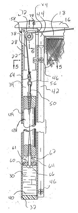
As illustrated in the partial cross-sectional view of
FIG. 2, the door control assembly 24 preferably comprises
several simple and inexpensive parts. A tube, sleeve, or
housing 28 preferably comprises plastic, metal (such as
aluminum) or other durable material. Housing 28
preferably includes an elongate hollow region or elongate
opening 34 disposed within the walls of the housing 28.
Housing 28 has a geometric cross-section which can be
square, rectangular, circular, or have any other desired
shape. Preferably, the cross-section 36 of housing 28 is
substantially square in shape as best illustrated in FIGS.
2t 63068
10 and 12. Housing 28 preferably includes a top opening
38 and a bottom opening 40. A seal or plug 32 is
preferably permanently secured into bottom opening 40 of
housing 28 to seal off the bottom end of the housing 28.
A mounting flange or mounting portion 42 is preferably
provided as an integral part of housing 28, as best
illustrated in FIG. 5.
The housing assembly 24 is preferably secured to the
sliding screen door 18 by mounting screws 46 inserted
through holes 47 in the mounting flange 42. The mounting
screws 46 are securely threaded into vertical frame member
44 of the sliding door 18 as best shown in FIGS. 2 and 5.
Referring to FIG. 2, the seal or plug 32 preferably
comprises plastic, rubber, or the like for providing a
substantially water-tight fit into the bottom opening 40
of housing 28. The housing 28 is filled with a liquid or
other viscous fluid 30, such as water or light grade oil,
thus providing a damping medium in the elongate opening
34. The water may be provided with antifreeze such as
ethylene glycol.
A weight 48 is provided to move upwardly and
downwardly within the confines of the elongate opening 34
of the housing 28. The weight 48 preferably comprises
lead, or similar relatively dense material, and is
preferably formed in a simple casting mold. The weight is
suspended from a cable 22 preferably attached to the top
of the weight 48 using a closed eye screw 50 threaded into
the top of the weight 48. A loop 56 of cable 22 engages
the annulus of closed eye screw 50. A clamp 54 may be
used to crimp or secure two portions of cable 22 in order
to provide loop 56. The cable 22 is entrained over a
pulley 52 and is attached at a fixed location 26 (see
Figs. 1, 3 and 8) at the opposite end of cable or tension
line 22.
The pulley 52 is supported at the top of the elongate
opening or passageway 34 of the housing 28 by a
21 63068
, .
positioning cap 58. The positioning cap 58 is inserted
into the top opening 38 of the housing 28, and is adapted
to hold the pulley 52 securely in place at the top of the
housing 28. Hence, weight 48 is supported by cable 22
S which extends over pulley 52.
A ported member or simple valve 60 is preferably
attached to the bottom of weight 48 using a screw 62
threaded into the bottom of weight 48. The valve mounting
screw 62 includes a shaft portion 64 extending below the
weight 48 for a pre-determined length until the screw 62
- terminates at a stop surface, stop portion, or head 66
thereof. The valve member 60 preferably comprises an
apertured square plate of plastic or similar suitable
material.
15The valve member 60 is slidably mounted to the shaft
64 using a hole 61 provided in the valve 60. The valve 60
slides upwardly or downwardly along the shaft portion 64
in response to an upward or downward motion of the weight
48 through the fluid 30. During an upward motion 94 of
20the weight 48, as illustrated in FIG. 9, the valve 60
comes to rest in a first position 96 against the head 66
of the valve mounting screw 62. During a downward motion
95 of the weight 48, as illustrated in FIG. 11, the valve
60 comes to rest in a second position 97 against the
bottom surface 51 of the weight 48.
As illustrated in FIG. 3, a second or remote end of
cable 22 is secured at fixed location 26 using mounting
bracket 70. Mounting bracket 70 includes a pin portion 76
for engaging a loop 72 formed substantially at the end of
cable 22. The loop 72 may be provided by folding over an
end of cable 22 onto a nearby portion thereof and engaging
the two portions of cable 22 by clamp 68. The mountlng
bracket 70 preferably includes two holes for accepting the
shaft of two screws 74. The screws 74 are preferably
threaded through each hole in the mounting bracket 70 and
through a frame portion 16 of the sliding door assembly
2~ 63068
12.
FIGS. 1 and 8 illustrate the preferred positioning of
fixed location 26 relative to the housing 28. Cable or
tension line 22 is preferably provided with a length just
slightly in excess of the range of motion of weight
assembly 49 in housing 28. The outer or second end 72 of
cable 22 is preferably secured at fixed location 26
substantially near the top of housing 28 when the sliding
door panel 18 is in the closed position and the housing 28
is attached thereto.
If the sliding door 18 opens to the left, as
illustrated in FIGS. 1 and 8, then the fixed location 26
is provided just to the right of the top of housing 28,
when the sliding screen door is closed. If the sliding
door 18 opens to the right, (not shown) then the fixed
location 26 is positioned just to the left of the top of
housing 28. Alternatively, the second end 72 of cable 22
can be attached to the sliding door 18 and the housing 28
can be attached at a nearby fixed location (not shown).
FIG. 5 is a cross-sectional view taken through the
top of housing 28 and the lower portion of cap 58.
Mounting screw 46 engages and secures mounting flange 42
of housing 28 to upright member 44 of sliding door 18.
Also with reference to FIG. 7, on sheet 1 of the drawings,
positioning cap 58 preferably includes two molded portions
78 which are fitted together prior to insertion into the
top opening 38 of housing 28. One or more assembly pins
82 are preferably provided in one of cap portions 78 and
corresponding pin holes or recesses 80 are provided in the
other cap portion 78. The pins 82 are inserted into holes
80 when the cap 58 is assembled.
FIG. 6 is a sectional view of the cap 58 illustrating
the pulley 52 being rotationally mounted on bearing
surfaces 86 provided on the inside walls of cap portions
78. The cap portions 78 and pulley 52 are preferably each
molded as a single piece of plastic material. Pulley 52
21 63068
preferably includes axle portions 88 disposed on opposing
sides of a groove 90 provided therein. Each axle portion
88 engages a respective bearing surface 86 thereby
supporting the pulley 52 in the cap 58 and allowing the
pulley to rotate about a horizontal axis 92.
Cable 22 is entrained in the groove 90 of pulley 52.
A silicone, oil-based, or other suitable lubricant may be
provided on the surfaces where the axle portions 88
contact the bearing surfaces 86. A hole 84 is provided in
the cap 58 substantially in alignment with the top of
groove 90 of the pulley 52. The cable 22 exits the cap 58
through the hole 84.
As illustrated in FIG. 8, an opening motion 19 of the
sliding door 18 creates a tension in cable 22 and raises
the weight assembly 49 within the housing assembly 24.
This results in an upward motion 94 of the weight assembly
49 within the housing assembly 24. As illustrated in
FIGS. 8 and 9, the upward motion 94 of weight assembly 49
through liquid 30 leaves the valve member 60 engaged
against the stop surface 66 of valve mounting screw 62,
corresponding to a first or open position 96 permitting
easy opening of the door.
As illustrated in FIG. 10, valve 60 has a geometric
cross-sectional shape 98 which preferably corresponds to
the geometric cross-sectional shape 36 of the housing 28.
In particular, FIG. 10 illustrates a square cross-
sectionally shaped housing 28 with a square cross-
sectionally shaped valve 60 adapted to have a tolerance
fit with the inner surface of housing 28. The tolerance
fit between the valve 60 and the housing 28 is provided to
be relatively close but is susceptible to a range of
values. For example, a clearance between the edges of the
valve 60 and the inner surface of the elongate opening 34
of approximately 1/64-1/32 inch is sufficient.
Preferably, the tolerance fit is such that sliding
friction between valve 60 and housing 28 is not
21 63068
appreciable and such that only relatively small amounts of
liquid 30 can pass through the relatively small space
provided therebetween when the weight assembly 49 is in
motion.
Valve 60 preferably includes a plurality of circular
openings, passages, or ports 100. Preferably, four
circular passages 100 are disposed concentrically and
symmetrically about the center point of the square cross-
section of valve 60. The passages allow the liquid 30 to
flow through the valve 60 as it moves directionally with
the weight 48. When the valve 60 is disposed in the open
position 96 as illustrated in FIG. 9, the passages 100 of
the valve 60 remain substantially unblocked to the flow of
fluid 30 through the passages 100. This allows the weight
assembly 49 to be accelerated or moved upwardly in
response to a door opening motion 19 while encountering
only a relatively small magnitude first damping force in
opposition to the upward movement.
Thus, a person is not hampered significantly by the
door control system 10 while opening door 18.
Significantly, the first damping force opposing the
upwardly moving weight assembly 49 may be used to
advantageously curb the tendency of door 18 to slam open
or accelerate excessively in response to a relatively
large impulse force applied to the door 18. The magnitude
of the upward or first damping force can be predetermined
by varying the features of one or more components of the
housing assembly 24, such as the size of the valve
passages 100.
Once sliding door 18 has been slightly opened, the
release of the door 18 creates tension in cable 22 due to
the gravitational force of the weight assembly 49 within
the housing assembly 24. This downward motion 95 of the
weight assembly 49 through the housing assembly 24 causes
the door 18 to close automatically when released in an
open position. As illustrated in FIG. 11, the downward
21 63068
-
14
motion 95 of weight assembly 49 through liquid 30 causes
the valve member 60 to be engaged against the bottom
surface 51 of weight 48, corresponding to a second or
restricted position 97.
As illustrated in FIG. 12, the cylindrical weight 48
includes a bottom surface 51 having a substantially
circular perimeter. The valve openings 100 are
substantially circular having a respective center
substantially aligned with the circular perimeter of
bottom surface 51. The bottom surface 51 of the weight 48
halts the translational motion of the valve 60 along the
shaft 64 when the weight 48 moves downwardly. This
corresponds to the second position 97 of the valve 60,
causing the partial blocking each of the valve openings
100 and providing a restricted opening area 102. qe
restricted flow of liquid 30 through the restricted
openings 102 provides a relatively large second damping
force in opposition to the downward movement 97 of the
weight 48. The relatively large magnitude second damping
force controls the closing rate of the door 18, providing
for a substantially uniform controlled and relatively slow
closing speed.
Although the system may be fabricated using various
materials and dimensions, one workable embodiment was made
using an extruded aluminum channel with an extending
flange, with the aluminum walls being about 1/16-inch
thick, and the weight being formed of a cylindrical lead
element about 1 and 13/16-inches in diameter and about 13
inches long. The value element was mounted on a screw and
was formed of a square pill of plastic about 7/8-inch on
a side and with a central hole for receiving the screw,
and four spaced openings about 1/4-inch diameter
overlapping the flat end of the lead weight, so that the
openings are partially blocked when the valve element
engages the lower end of the weight. The channel was
filled with water and appropriate amounts of mineral oil,
21 63068
depending on local weather conditions. The channel was
approximately 5 1/2-feet long to accommodate the usual
maximum opening of a sliding door such as a screen door
which would be a foot or so less than the height of the
channel. The tension line was formed of nylon coated
cable.
The foregoing description illustrates principles
embodying an inexpensive, simple, reliable, easily
installed system or kit for automatically closing a door
in a controlled manner while also maintaining the ease and
ability of opening the door in a substantially unhindered
fashion. Accordingly, the foregoing details can be
modified without detracting from the principles embodying
the present invention. For example, the door control
system 10 may be used on virtually any type of door
without loss of generality. The cross-sectional shape of
the housing 28 may be provided as circular, rectangular,
or some other shape. Similarly, the cross-sectional shape
of the weight 48 may be changed. The cross-sectional
shape of valve 60 may be modified as well. The size of
the valve openings 100 may be adapted to provide larger or
smaller magnitude damping forces. Some of the openings
may remain unblocked and others fully blocked by the lower
surface of the weight when the value member engages the
lower end of the weight. These and other modifications
would become evident from reading the foregoing
description embodying principles of the present invention.
Accordingly, the present invention should not be limited
to the specific embodiments shown in the drawings and
described in detail hereinabove.