Note: Descriptions are shown in the official language in which they were submitted.
CA 02163221 2001-O1-16
1
TITLE OF THE INVENTION
Process and apparatus for the purification of graphite
FIELD OF THE INVENTION
The present invention relates to an apparatus and a process
for the confinement of chlorine gas at high temperature in the course of
chlorination operations on various substrates.
BACKGROUND OF THE INVENTION
The use of chlorine gas at high temperature is quite common
in many processes. For Example, treatment of impure graphite is reported as
a technique for the purification of graphite.
In all these operations, chlorine at temperatures from 800 to
more than 1600°C must be contained inside a reaction vessel and it has
been found that the material showing the ideal resistance to the otherwise
extremely corrosive action of C12 at high temperature is graphite.
But graphite has a very serious drawback as a material for
handling hot chlorine: chlorine diffuses very readily through this substance.
Therefore, if a reactor or a reacting chamber is made of graphite inside a
steel shell, chlorine, especially at high temperature, will diffuse outwards
very
readily and attack the external metallic wall, thus destroying the apparatus.
It would be highly desirable to use graphite reactors or reaction
vessels in chlorination apparatus because of the very high stability of this
form of carbon at high temperature if it were possible to prevent the adverse
diffusion of chlorine outside of these graphite reactors or vessels.
Numerous attempts have been made in the past to provide
moderate to high temperature treatments of substrates with chlorine.
CA 02163221 1997-11-28
2
However, it has been found that such operation was destructive for the
equipment and therefore this approach did not receive the industrial
applications which it deserved. This was due mainly to the great permeability
of graphite toward chlorine, and it was noted that, for lack of material that
can
contain chlorine at an operating temperature between 800 and 1600°C,
the
gas would not discriminate between the substrate under treatment and the
heating system, thus resulting in severe attack on both. Therefore, extreme
corrosion prevented the use of a technique that would otherwise have
allowed high performances.
OBJECTS AND STATEMENT OF THE INVENTION
It is an object of the present invention to define a process
allowing reactions inside a reactor chamber made of graphite, with
appropriate substrates, while preventing diffusion of chlorine through the
walls of the reaction chamber.
Thus, the present invention is first concerned with a method
whereby the permeability of graphite is put to use in order to avoid leakage
of aggressive chlorine outside of the graphite reactor used for the reaction.
The implementation of reactions with chlorine calls for
temperatures in the range of 800 to more than 1600°C. At these
temperatures, a graphite reactor must be protected from atmospheric
oxidation. Therefore, the present invention uses an atmosphere of an inert
gas which does not react with carbon and an outside metallic shell for the
containment of the inert atmosphere.
It has been found that, if a blanket of inert gas is circulated
within the graphite walls of the reaction vessel and if the pressure inside
the
reactor is kept slightly below the pressure of the inert gas within the wall
of
~a
CA 02163221 1997-11-28
3
the vessel which contains the atmosphere of chlorine, the chlorine is retained
completely inside the reaction vessel.
The present invention therefore relates to a process for
reacting a substrate with hot chlorine, the substrate being contained in the
core of a reactor defined by enclosing walls made of graphite, the walls
including a passageway therein; the process comprising the steps of:
- circulating an inert gas under pressure in the passageway
within the graphite wall of the reactor;
- circulating chlorine under pressure in the core to react with the
substrate;
- maintaining the pressure of the inert gas within the wall at a
value higher than the pressure of the chlorine inside the
reacting chamber so that chlorine permeating from the
chamber through the wall is swept inside the core by the inert
gas in the passageway and prevented from permeating
completely through the wall; and
- maintaining a temperature in the core at a value sufficient to
obtain the desired reaction.
The present invention is further concerned to provide a
geometry of construction of graphite reactors so as to allow reactions, inside
the reactor chamber made of graphite, with appropriate substrates while
preventing diffusion of chlorine through the walls of the reaction chamber.
The invention therefore further relates to an apparatus for
implementing the above process, which comprises:
- a reactor having a core to receive therein substrate and walls
around the core, the walls being made of graphite and defining
a passageway therein;
g
CA 02163221 1997-11-28
4
- first inlet means to the core for allowing ingress of chlorine to
react with the substrate in said core;
- second inlet means to the passageway for allowing ingress of
an inert gas under pressure in the passageway;
- heating means surrounding the walls to maintain a
temperature at a value sufficient to react chlorine with the
substrate; and
- outlet means from the core for allowing egress of said chlorine
inert gas and volatile components.
In one preferred form of the invention, the inert gas is selected
from a group comprising nitrogen, argon and helium, nitrogen being
preferred.
In another form of the invention, the ratio of the pressure of the
inert gas to the pressure of the chlorine is from 1.2 to 5, preferably 3.
Other objects and further scope of applicability of the present
invention will become apparent from the detailed description given
hereinafter. It should be understood, however, that this detailed description,
while indicating preferred embodiments of the invention, is given by way of
illustration only, since various changes and modifications within the spirit
and
scope of the invention will become apparent to those skilled in the art.
IN THE DRAWINGS
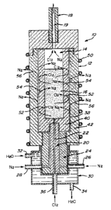
Fig. 1 is a cross-sectional view schematically representing an
apparatus for carrying out the present invention.
DESCRIPTION OF PREFERRED EMBODIMENTS
The annexed figure 1 illustrates an apparatus, generally
designated 10, having a main body 12 provided with a central reaction
CA 02163221 1997-11-28
chamber 14 in which is received a substrate 16 to be treated. The body 12
has an outlet port 18 with a passage 19 in communication with the upper part
of the chamber 14 and an inlet port 20 having a central passage 22 in
communication with the lower part of the chamber 14. Surrounding the inlet
5 port is a second body 24 having a pair of inlets 26 and 28 to receive an
inert
gas, such as nitrogen. Body 24 is enclosed within a third body 30 having an
inlet port 32 and an outlet port 34 for the circulation of water inside the
body.
The water serves as a refrigerant for the walls of body 24.
A coil 50 is schematically represented to indicate that heat is
required and provided in order to treat the content 16 in the reactor. A
metallic envelope to the apparatus has not been shown.
Body 24 has an inlet 36 for chlorine to be received within the
chamber via passage 22. The inert gas introduced at inlets 26 and 28
circulates in the space between port 20 and body 24 and then through the
surrounding area 38 defined between the inner wall 40 and the outer wall 42
of the body 12.
As illustrated by the various arrows 52 in figure 1, it can be
seen that the chlorine introduced within the central chamber and attempting
to diffuse outwardly through the wall 40 is returned inwardly as it reaches
the
passageway 38; it is swept inward by the high pressure of the inert gas in the
passageway 38 which may also permeate through the walls 40 and 42 as
indicated by arrows 54 and 56, respectively.
The implementation of the present invention calls for the
adjustment of three variables; namely, the relative pressure within the
reactor, the pressure ratio existing between chlorine and nitrogen and the
ratio of thickness of the inner wall 40 and the outer wall 42 of the reactor.
CA 02163221 1997-11-28
6
The relative pressure within the reactor as related to
atmosphere must be kept negative so as to insure that the excess chlorine
and other products are evacuated through the intended port 18 and do not
tend to diffuse through the top cover. A negative pressure from 100 to 1000
Pascal proved to be appropriate.
The ratio of pressure of nitrogen to chlorine is a critical
parameter. Chlorine, as it flows through the substrate layer 16 to be reacted,
must have a positive pressure to insure an appropriate flow through the
reacting bed. This positive pressure existing at the chlorine inlet at the
bottom of the reactor is the main site of potential leaks. To correct this
situation, the absolute pressure of nitrogen within the wall must be kept at
values from two to five times the absolute pressure of chlorine. Under those
conditions, no leakage of chlorine is observed.
The ratio of the thickness of the inner and outer walls
determines the distribution of nitrogen leakage. This ratio may also be
influenced by the density of the graphite walls, such density being related to
porosity. Mechanical constraints may also enter into consideration. An inner
chamber with high density material and with a 1:1 to 1:2 inner-to-outer wall
width ratio gave excellent performances.
Examples
1. Determination of chlorine leakage
A demonstration reactor has been built, having an inner
diameter of 7.62 cm, the thickness of the inner wall being 2.54 cm (ratio
1:4).
A layer of 25 cm of impure graphite (85% C content) having an average
particle size of 75 micron was loaded in the reactor. A vacuum of 1100 Pa
was applied at the outlet of the reactor which was placed inside a steel
envelope and was heated by arc on the bottom of the graphite cell.
CA 02163221 1997-11-28
7
A positive pressure of chlorine was admitted at the bottom of
the reactor (1400 Pa) while the nitrogen pressure in the wall was kept at
4200 Pa. The system operated for eight hours and the outside surface
probed for chlorine leak using a silver nitrate detector. No detectable
chlorine
could be measured either by chemical test or by olfaction. Copious
production of volatile chlorides was noted at the outlet of the reactor.
2. Purification of graphite
Using a reactor as described in Example 1, a sample of natural
graphite was treated with chlorine in excess at 1750°C for 30 minutes.
The
starting material, StratminT"" grade +5094, contained 94% of elemental
carbon. After the operation, the carbon content was 99.99% t 0.01 %. No
chlorine leakage was noted during this very high temperature operation.
Although the invention has been described above with respect
with one specific form, it will be evident to a person skilled in the art that
it
may be modified and refined in various ways. It is therefore wished to have
it understood that the present invention should not be limited in scope,
except by the terms of the following claims.
i