Language selection

Search

Patent 2163243 Summary

Third-party information liability

Some of the information on this Web page has been provided by external sources. The Government of Canada is not responsible for the accuracy, reliability or currency of the information supplied by external sources. Users wishing to rely upon this information should consult directly with the source of the information. Content provided by external sources is not subject to official languages, privacy and accessibility requirements.

Claims and Abstract availability

Any discrepancies in the text and image of the Claims and Abstract are due to differing posting times. Text of the Claims and Abstract are posted:

  • At the time the application is open to public inspection;
  • At the time of issue of the patent (grant).
(12) Patent Application: (11) CA 2163243
(54) English Title: STABILISING ARRANGEMENT, IN PARTICULAR FOR STABILISING THE SPINAL COLUMN
(54) French Title: DISPOSITIF DE STABILISATION, NOTAMMENT DE LA COLONNE VERTEBRALE
Status: Dead
Bibliographic Data
(51) International Patent Classification (IPC):
  • A61B 17/80 (2006.01)
  • F16B 39/32 (2006.01)
  • A61B 17/70 (2006.01)
(72) Inventors :
  • BIEDERMANN, LUTZ (Germany)
  • HARMS, JURGEN (Germany)
(73) Owners :
  • BIEDERMANN MOTECH GMBH (Germany)
(71) Applicants :
(74) Agent: GOUDREAU GAGE DUBUC
(74) Associate agent:
(45) Issued:
(86) PCT Filing Date: 1995-03-01
(87) Open to Public Inspection: 1995-09-28
Availability of licence: N/A
(25) Language of filing: English

Patent Cooperation Treaty (PCT): Yes
(86) PCT Filing Number: PCT/EP1995/000745
(87) International Publication Number: WO1995/025474
(85) National Entry: 1995-11-17

(30) Application Priority Data:
Application No. Country/Territory Date
P 44 09 833.2 Germany 1994-03-22

Abstracts

English Abstract


A stabilizer device, in particular for stabilizing the spinal
column, comprises a stabilizer plate (1) having a first end (12)
and an opposite second end (13) and at least one hole (14) at
each end for receiving bone screws having a threaded shaft (21)
for screwing in when rotating in the first direction and
unscrewing when rotating in a second direction. The bone screws
are secured against unintentional rotation in the second
rotating direction by means of a locking device (15). The
locking device (15) comprises a resilient member (30, 31, 32)
engaging the bone screw to be received, the resilient device
being formed as a portion of the stabilizer plate (1) and
deflectable from the locking position thereof in a recess (35)
of the stabilizer plate (1) during rotation in the first
direction.


French Abstract

L'invention a pour objet un dispositif de stabilisation, notamment de la colonne vertébrale, présentant une plaque de stabilisation (1) avec une première extrémité (12) et, à l'opposé de celle-ci, une seconde extrémité (13) présentant au moins un trou (14) pour y loger des vis à os dotées d'une tige filetée (21) vissable dans un premier sens de rotation et dévissable dans un second sens de rotation. Les vis à os sont bloquées par un dispositif d'arrêt (15), ce qui permet d'empêcher une rotation accidentelle dans le second sens de rotation. Le dispositif d'arrêt (15) comporte un élément ressort (30, 31, 32) qui bloque la vis à os en s'engageant dans celle-ci. Cet élément ressort est constitué d'une partie de la plaque de stabilisation (1) et peut se dégager de sa position d'arrêt, lors du vissage dans le premier sens de rotation, pour se loger dans un creux (35) de ladite plaque de stabilisation (1).

Claims

Note: Claims are shown in the official language in which they were submitted.


Claims

1. Stabilizer device, in particular for stabilizing the spinal
column, comprising a stabilizer plate (1) having a first end
(12) and a second end (13) opposite to the first end and at
least one respective hole (14) at each end for receiving bone
screws (2), the bone screws having a threaded shaft (21) for
screwing in a first rotating direction and unscrewing a second
rotating direction, characterized in that a device (15, 23) for
locking the bone screws against unintentional rotation in the
second rotating direction is provided.


2. Stabilizer device according to claim 1,
characterized in that the locking device (15) comprises a
resilient member (30, 31, 32) engaging the bone screw to be
received.


3. Stabilizer device according to claim 2,
characterized in that the bone screw (2) comprises a screw head
(20) being adjacent to the threaded shaft (21) and comprising,
at the periphery thereof, a toothing (23) engaging the resilient
member for providing the lock.


4. Stabilizer device according to claim 3,
characterized in that the toothing (23) is formed in such a
manner that a first tooth flank (51) points in radial direction
of the screw head (20) and a second tooth flank (52) is formed
including an acute angle with this radial direction, and that
the second tooth flank precedes the first tooth flank in the
sense of the first rotating direction.


5. Stabilizer device according to claim 3 or 4,
characterized in that the hole (14) is formed as an elongate
hole having a longitudinal axis pointing at the two ends (12,
13) of the plate, the elongate hole being superimposed by a
circular hole having the same diameter and a countersink (16)
for fittingly receiving the screw head (20), whereby the center
(M) of the circular hole is located on the longitudinal axis of
the elongate hole and offset from the center of the elongate
hole towards the opposite end of the plate.


6. Stabilizer device according to any of the claims 2 to 5,
characterized in that the resilient member (30, 31, 32) is
formed as a portion of the stabilizer plate (1) lying in the
plane of the plate.


7. Stabilizer device according to claim 6,
characterized in that the resilient member has a curved web
portion (30) connected with the stabilizer plate (1) and a
straight web portion (31) joined thereto on the side of the
center of curvature and including an acute angle with the curved
web portion, the straight web portion having a free end which is
bent towards the curved web portion, the curvature of the curved
web portion (30) being a left-hand curvature when seen from the
point of connection with the stabilizer plate.


8. Stabilizer device according to claim 6 or 7,
characterized in that the resilient member can be deflected in a
recess (35) of the stabilizer plate (1) in direction of the
center of curvature of the curved web portion (30).


9. Stabilizer device according to claim 8,
characterized in that the resilient member is formed so that a
tip (17) formed between the curved web portion (30) and the
straight web portion has, in unstressed state of the resilient
member, a distance from the center of the circular hole which is
smaller than the radius of the circular hole.


10. Stabilizer device according to claim 8 or 9,
characterized in that the resilient member is formed so that the
tip (17) thereof is, in a deflected position of the resilient
member, in a distance from the center of the circular hole which
is larger than or equal to the outer radius of the countersink
(16) surrounding the circular hole.


11. Stabilizer device according to any of the claims 3 to 10,
characterized in that the head (20) of the bone screw (2)
comprises an edge having the shape of a substantially spherical
segment, whereby the center of the spherical segment is on the
side opposite to the threaded shaft (21).


12. Stabilizer plate according to claim 11,
characterized in that the countersink (16) of the circular hole
is adapted to match the shape of the screw head (20).


13. Stabilizer device according to any of the claims 1 to 12,
characterized in that two holes (14) are provided at each of the
first (12) and second (13) end of the stabilizer plate (1).

14. Stabilizer device according to any of the claims 1 to 13,
characterized in that the stabilizer plate (1) together with the
lock device (15) and the bone screw (2) are made of a physically
friendly metal, preferably titanium.


15. Stabilizer device according to any of the claims 3 to 14,
characterized in that the bone screw (2) has a recess (55) for
inserting a wrench for rotating the screw, the recess being
provided at the end of the screw head (20) opposite to the
threaded shaft.
Description

Note: Descriptions are shown in the official language in which they were submitted.


~32~3


Stabilizer Device,
in particular for stabilizing the spinal column
______________________________________________________________


The invention relates to a stabilizer device, in particular for
stabilizing the spinal column, according to the preamble of
claim 1.

Stabilizer devices are used for connecting two vertebrae of the
spinal column in particular in the cervical region. Conventional
stabilizer devices consist of a stabilizer plate which is
fastened by means of at least two bone screws which are screwed
into the respective vertebra to be connected.

Especially in the region of the cervical vertebra the head
movement tends to loosen or rotate or even knock out the screws.
Thus a stable connection of the vertebrae is no longer
guaranteed.

It is the object of the invention to provide a stabilizer device
which secures the screws against releasing rotation.

The subject is achieved by a stabilizer device according to
claim 1.

It is the advantage of the stabilizer device that the lock of
the screws against unintentional unscrewing is designed such
that each screw can easily be screwed into the material and no
externally mounted device for locking the bone screw against
unintentional unscrewing is required. Thus conventional srew
securing techniques using for example resilient toothlock
washers, cover flaps or the like which are rather inconvenient
to handle during an operation at the spinal column can be
omitted.

2~632


Advantageous developments are defined in the subclaims.

In the following an embodiment is described with reference to
the figures.

In the figures:

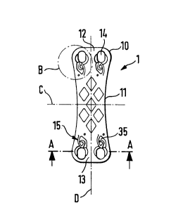
Fig. 1 shows a top view of the stabilizer plate;
Fig. 2 is an enlarged sectional view along line
A - A of Fig. 1;
Fig. 3 is an enlarged representation of the portion
B of Fig. 1;
Fig. 4 is a side view of a bone screw;
Fig. 5 is a top view of the head of the bone screw
of Fig. 4;
Fig. 6 is a sectional view showing a state of a bone
screw when screwed in but before being
finally secured;
Fig. 7 is a sectional view showing the bone screw in
the final screwed-in state.

As shown in Fig. 1 the stabilizer device comprises a
substantially rectangular stabilizer plate 1. In the further
description the center line of the plate extending in
longitudinal direction of the rectangle is referred to as D and
the center line extending transversally thereto in cross-section
of the rectangle is referred to as C.

The stabilizer plate 1 is shaped to have rounded corners 10 and
longitudinal sides 11 which are curved symmetrically towards the
center line D.

The plate comprises a first end 12 and an opposite second end 13
each having two bores 14 for receiving bone screws. The bores 14
are arranged to be in pairs symmetric with respect to the center
line C and to the center line D, respectively, of the plate.

h ~

As shown in Fig. 3 each bore 14 is an elongate hole having the
larger diameter thereof extending parallel to the center line D.
The elongate hole is superimposed by a circular hole having a
diameter which is equal to the smaller diameter of the elongate
hole, whereby the center M of the circular hole is located on
the longitudinal axis of the elongate hole and offset from the
center of the elongate hole in the direction towards the center
line C. The circular hole is provided with a countersink 16 for
fittingly receive the screw head of a bone screw 2 which will be
described in detail further below.

As shown in Fig. 1 the stabilizer plate 1 has a lock member 15
for locking the bone screw 2, the lock member being provided at
the end of each bore 14 facing the center line C of the
stabilizer plate 1.

The lock member 15 is formed as a resilient member being a part
of the stabilizer plate 1 and lying in the plane of the plate.
It is produced by cutting out the stabilizer plate and can be
deflected in direction of the plane of the plate in a recess 35
produced in the stabilizer plate 1 by this cut-out operation.

As shown in Fig. 3 the lock member comprises a curved web
portion 30 having one end passing over into the stabilizer plate
1. The other end thereof is joined, at the side facing the
center of curvature, to a straight web portion 31 including an
acute angle with the curved web portion and having a free end
bent towards the curved web portion 30. The curvature of the
curved web portion 30 is a left hand curvature when seen from
the connection to the stabilizer plate. The tip 17 of the lock
member 15 formed by the curved web portion 30 and the straight
web portion 31 has a distance from the center M of the circular
hole which is smaller than the radius of the circular hole, i.e.
the tip 17 slightly projects into the circular hole which can
also be seen in the sectional view of Fig. 2.

~ ~ B3% ~3

The straight web portion 31 extends in radial direction of the
circular hole and includes an angle of about 60 with the curved
web portion in the region of the tip 17. The lock member 15 is
resilient and can be deflected within the recess 35 of the
stabilizer plate 1 from the above-described unstressed position
(shown in full lines in Fig. 3) in direction of the center of
curvature of the curved web portion 30 (broken line in Fig. 3).
The side of the curved web portion opposite to the center of
curvature is adjacent to the plate body 60. In the deflected
position shown in broken lines the distance of the tip 17 of the
lock member from the center M of the circular hole is larger
than or equal to the outer radius of the countersink 16
surrounding the circular hole.

The stabilizer device further comprises bone screws 2 for
mounting the stabilizer plate 1, as shown in Fig. 4. The bone
screw 2 comprises a screw head 20 and a threaded shaft 21. At
one side thereof the screw head 20 is connected with the
threaded shaft and comprises an edge which is substantially
shaped as a spherical segment. The center of this segment is on
the side opposite to the threaded shaft and on the longitudinal
axis of the screw. The diameter of the screw head is equal to or
slightly smaller than the diameter of the countersink 16 of the
circular hole. The spherically curved edge of the screw head 20
is provided with a toothing 23 which may be engaged by the lock
member 15 for locking the screw.

As shown in Fig. 5 the toothing 23 is formed in such a way that
each tooth is defined by a first tooth flank 51 extending in
radial direction of the screw head and a second tooth flank 52
including an acute angle with this radial direction. The
arrangement of the second tooth flank is selected to precede the
first tooth flank in the first clockwise rotating direction.
When screwed in the screw head 20 is placed within the
countersink 16 of the circular hole and the straight web portion
31 of the lock member 15 abuts the first tooth flank 51 of the
toothing 23 for providing a lock.

5 2~,~32'~


At the side of the screw head 20 opposite to the threaded shaft
21 a hexagon hole 55 receiving a wrench for rotating the screw 2
is provided in the center of the screw head 20.

The stabilizer plate 1 and the bone screw 2 are made out of a
physically friendly material, preferably of titanium.

The operation of the locking device according to the Figures 1
to 5 is as follows: When screwing in the screw in the first
clockwise rotating direction each of the second tooth flanks 52
of the screw head 20 slide along the curved web portion 30 of
the lock member 15 as soon as the screw head 20 arrives in the
region of the countersink 16. Thereby the lock member is
deflected by the tooth flanks 52 sliding therealong in such a
manner that the straight web portion 31 is pushed out from the
lock position thereof by the first tooth flank 51. The tip 17 of
the lock member then has a respective distance from the center M
of the circular hole which is larger than the radius of the
circular hole. After the passage of each second tooth flank 52
the resilient lock member 15 snaps into the above-described lock
position thereof.

When attempting to rotate the screw in a second rotating
direction opposite to the first rotating direction for
unscrewing the screw the first tooth flank 51 of the toothing is
pressed against the straight web portion 31 of the lock member
and the tip 17 of the lock member is clamled in the toothing.
Thus, unscrewing the screw is impossible without using
additional auxiliary equipment for deflecting the lock member
into the position shown in broken lines.

The mounting of the stabilizer plate 1 will now be described
with reference to the Figures 6 and 7.

6 2~ S32 ~3


Figure 6 is a sectional view of a portion of the stabilizer
plate 1 comprising the hole 14 and the screw head in a position
before the final fixation. The screw is positioned at about the
longitudinal center of the elongate hole. Thereupon the threaded
shaft 21 is screwed in until the screw head 20 pushes against an
upper edge 18 of the edge of the elongate hole which is not
countersunk.

When further rotating the screw in the first rotating direction
the screw head 20 is pushed away from this upper edge 18 and
pulled into the fitting countersink 16 of the circular hole
superimposing the elongate hole. This centers the head 20 of the
bone screw 2 within the circular hole whereby the respective
vertebrae which are bolted to the first or second end,
respectively, of the stabilizer plate are pressed onto each
other. Fig. 7 is a sectional view of the stabilizer plate 1 and
of the bone screw 2 when completely screwed in.

The transverse diameter of the elongate hole and therefore the
diameter of the hole belonging to the center of the countersink
16 is selected in relation to the shaft of the screw 2 so that,
as shown in Fig. 6, the screw 2 may be inserted in an inclined
position which includes an angle of up to 15 from the axis of
the hole. Since as apparent from Fig. 4 or Fig. 7 the tooth
flanks extend over almost the entire height of the head in axial
direction the lock obtained in the above-described manner also
occurs if the screw is inserted in inclined position.

Representative Drawing
A single figure which represents the drawing illustrating the invention.
Administrative Status

For a clearer understanding of the status of the application/patent presented on this page, the site Disclaimer , as well as the definitions for Patent , Administrative Status , Maintenance Fee  and Payment History  should be consulted.

Administrative Status

Title Date
Forecasted Issue Date Unavailable
(86) PCT Filing Date 1995-03-01
(87) PCT Publication Date 1995-09-28
(85) National Entry 1995-11-17
Dead Application 2003-03-03

Abandonment History

Abandonment Date Reason Reinstatement Date
2002-03-01 FAILURE TO PAY APPLICATION MAINTENANCE FEE
2002-03-01 FAILURE TO REQUEST EXAMINATION

Payment History

Fee Type Anniversary Year Due Date Amount Paid Paid Date
Application Fee $0.00 1995-11-17
Registration of a document - section 124 $0.00 1996-02-15
Maintenance Fee - Application - New Act 2 1997-03-03 $100.00 1997-02-19
Maintenance Fee - Application - New Act 3 1998-03-02 $100.00 1998-02-09
Maintenance Fee - Application - New Act 4 1999-03-01 $100.00 1999-02-10
Maintenance Fee - Application - New Act 5 2000-03-01 $150.00 2000-02-15
Maintenance Fee - Application - New Act 6 2001-03-01 $150.00 2001-02-05
Owners on Record

Note: Records showing the ownership history in alphabetical order.

Current Owners on Record
BIEDERMANN MOTECH GMBH
Past Owners on Record
BIEDERMANN, LUTZ
HARMS, JURGEN
Past Owners that do not appear in the "Owners on Record" listing will appear in other documentation within the application.
Documents

To view selected files, please enter reCAPTCHA code :


To view images, click a link in the Document Description column. To download the documents, select one or more checkboxes in the first column and then click the "Download Selected in PDF format (Zip Archive)" or the "Download Selected as Single PDF" button.

List of published and non-published patent-specific documents on the CPD .

If you have any difficulty accessing content, you can call the Client Service Centre at 1-866-997-1936 or send them an e-mail at CIPO Client Service Centre.


Document
Description 
Date
(yyyy-mm-dd) 
Number of pages   Size of Image (KB) 
International Preliminary Examination Report 1995-11-17 21 696
Representative Drawing 1999-06-02 1 5
Description 1995-09-28 6 257
Cover Page 1996-04-02 1 20
Abstract 1995-09-28 1 22
Drawings 1995-09-28 2 30
Claims 1995-09-28 4 121
Fees 2000-02-15 1 41
Fees 1999-02-10 1 47
Fees 1998-02-09 1 50
Fees 2001-02-05 1 39
Fees 1997-02-19 1 140