Note: Descriptions are shown in the official language in which they were submitted.
2 1~3288
ENGINB DEMAND FUEL DBLIVERY 8Y8TEM
Field of the Invention
This invention relates to a method and apparatus for
controlling the delivery of fuel to an internal combustion engine
and more particularly to a method and apparatus for delivering fuel
as a function of engine fuel demand.
Background
In many small engine fuel delivery systems currently in
use, fuel is fed by a constant-delivery pump from a fuel tank to
the engine, and excess fuel is returned from the engine to the
tank. The returned fuel carries engine heat to the fuel supply
which can significantly increase the temperature and vapor pressure
of the fuel in the tank. Venting fuel vapor to the atmosphere to
relieve pressure caused by the heated returned fuel is undesirable
because it would release hydrocarbons that are carcinogenic or
which can form damaging oxidants such as ozone. Venting is also
undesirable because it significantly reduces fuel mileage. When
heated, the liquid fuel in the fuel tank can also vapor-lock the
fuel pump causing the engine to stop or not start until the fuel in
the tank has cooled. Constant fuel pump operation is also
undesirable because it increases electrical power consumption while
decreasing both pump life and fuel filter life.
Currently, fuel pumps that supply fuel to electronically
fuel injected internal combustion small engines are oversized so
- ~ 2163~8
they always provide an adequate amount of fuel to the engine, even
during worst case and maximum load engine operating conditions.
These worst case conditions can occur while the engine is operating
at wide open throttle such as during hard acceleration or during
towing, when heavily loaded, or while climbing a hill having a
steep incline. During worst case and maximum load conditions, the
engine requires significantly more fuel than while idling and
during normal load operation.
Although, it is desirable to supply more fuel to the
engine than it is using during operation for maintaining adequate
fuel pressure at each injector, oversizing the fuel pump causes the
pump to supply significantly more fuel to each injector than is
required during idle and normal engine operating conditions. The
result is also decreased filter life and increased electrical power
consumption.
Unfortunately, particularly for small engine
applications, because they utilize relatively small electrical
alternator and generator systems, they frequently have insufficient
power output at low speeds and increased electrical consumption can
detrimentally affect operation by excessively increasing the
electrical load on the alternator or generator thereby reducing its
life. If electrical power demands exceed the output capacity of the
alternator or generator, electrical power will be drawn from the
battery to make up the power deficit reducing battery life. With
present day electrical power demands rising due to an ever
increasing number of convenience devices being powered by the
engine, such as convenience lights, head lights, brake lights
~163~8
. ,
stereos, compact disc players and cellular phones on motorcycles,
fish-locators on boats, and lights, handlebar heaters, engine
operation monitoring instruments on snowmobiles, as well as other
electric power consuming devices and instruments, every effort is
being made by the design engineer to minimize the electrical power
consumption of all engine components requiring power.
Attempts have been made to reduce electrical consumption
by varying fuel pump output in response to engine demand as sensed
by fuel line pressure. This type of fuel delivery system varies the
speed of the fuel pump in response to the engine fuel demand and,
hence, fuel pressure downstream of the pump thereby lessening
electrical power consumption. Representative of this type of fuel
delivery system are U.S. Patents: Tuckey 4,728,264; Tuckey
4,789,308; Tuckey 4,926,829; Tuckey, et al. 5,044,344; Tuckey et
al. 5,120,201; Tuckey 5,148,792; and Tuckey 5,265,644.
However, these systems require at least one additional
component, such as a pressure sensor or regulator, that provides an
indication of fuel pressure downstream of the fuel pump to vary
fuel pump operation. Additionally, these systems can be slow to
react because sensing fuel pressure indicates present engine
demand, not anticipated future demand. As such, there can be a time
lag in delivering a sufficient amount of fuel should fuel demand
quickly rise dramatically possibly causing the engine to stumble
temporarily until sufficient fuel is supplied by the fuel pump to
meet demand.
~ First Inertia Switch, of Grand Blanc, Michigan, makes an
add-on fuel pump driver for variably controlling operation of a
~1632~8
fuel pump using only the fuel injector operating signal from the
engine control unit of an internal combustion engine. This fuel
pump driver is used in larger engine, automotive applications and
consists of a modular box that houses a fuel pump driver circuit
with external wiring connecting the driver to the fuel injector
control signal at the fuel injectors and external wiring connecting
the driver to the fuel pump. Both sets of external wiring can be
susceptible to conducted and radiated electromagnetic interference
(EMI) and radio frequency interference (RFI) creating "noise"
within the wiring which can undesirably affect fuel pump operation.
Furthermore, tapping the fuel injector control signal reduces the
signal level possibly negatively affecting fuel injector operation.
Additionally, because the engine compartment is crowded and for
aesthetic reasons, it is also undesirable to have the fuel pump
driver mounted near the engine in relatively close proximity to the
fuel injectors.
Although faster in response than the aforementioned
pressure sensing fuel delivery system references, the First Inertia
fuel pump driver module also adjusts fuel pump output in response
to actual demand. Even so, a lag in fuel delivery due to a
relatively sharp rise in fuel demand can also occur because the
First Inertia driver must first wait for the engine control unit
(ECU) to calculate and send the fuel injector control signal to
each fuel injector before it can determine and signal the fuel pump
how much fuel should be delivered. In some instances, this lag may
be significant, particularly when demand steeply rises during full
load or wide open throttle conditions, because the First Inertia
-- ~163288
-
fuel pump driver module has no way of sensing engine fuel demand
any earlier, such as by sensing throttle position, for increasing
fuel delivery to coincide with the rise in demand. To compensate
for any such time lag in increasing fuel delivery, the fuel pump
driver must cause the fuel pump to supply more excess fuel at
virtually all other times of operation than it would if it
determined engine fuel demand earlier so any rapid increase in
demand would not leave the engine without sufficient fuel.
~ummary of the Invention
A fuel delivery system for a fuel injected internal
combustion engine wherein operation of the fuel pump is controlled
to supply at least as much fuel as is being demanded by the engine
while reducing electrical power consumed by the fuel pump. The fuel
delivery system has an engine control unit (ECU) that communicates
with the engine to predetermine how much fuel the engine will need
based upon engine operating parameters, such as engine speed and
throttle position, mass airflow entering the engine, and/or engine
ignition. This engine fuel demand information is used to determine
a fuel pump control signal communicated by the ECU to a fuel pump
driver that controllably drives the pump to vary its fuel output in
response to the control signal generated by the ECU. Preferably,
the fuel pump control signal formulated by the ECU causes the fuel
pump driver to vary the duty cycle of the pump to provide as much
fuel to each fuel injector of the engine as is being demanded by
the engine for maintaining proper fuel pressure at each injector
~328~
while providing sufficient excess fuel to meet sudden increases in
fuel demand. Preferably, there is a fuel pressure regulator
downstream of the fuel pump to regulate the pressure of fuel
supplied to each injector to ensure each injector meters the
desired amount of fuel during its intake stroke of engine
operation.
Preferably, the ECU monitors engine operation to
determine how much fuel each injector must mix with air entering
the engine to ensure efficient engine operation. To do so, the ECU
uses the engine fuel demand information to generate a fuel injector
driver signal that is sent to each fuel injector for controlling
how long each injector will stay open dispensing fuel during its
next intake stroke of engine operation.
Preferably, in determining the fuel pump control signal,
the ECU multiplies engine speed by the duration that each fuel
injector will stay open for determining the rate that fuel should
be supplied to the engine to satisfy engine demand. Preferably, to
determine how much fuel to supply to the engine in formulating the
fuel pump control signal, the resulting calculated fuel demand is
further multiplied by a constant chosen to ensure that more fuel
will be supplied to the engine than will be consumed by the engine
to ensure that the desired fuel pressure at each injector is
maintained and that there is sufficient excess fuel to meet any
sudden increases in fuel demand. Preferably, the constant is
greater than unity so that more fuel is supplied to the engine than
demanded. For example, the constant can be chosen so that the fuel
pump always supplies at least five-to-ten percent more fuel than is
~1632~
demanded by the engine. Other constants of greater or lesser value
may be determined or selected if it is desirable to supply greater
or less excess fuel to the engine.
The fuel pump control signal generated by the ECU
controls the duty cycle of electrical power supplied by the fuel
pump driver to the fuel pump thereby controlling the duty cycle of
operation of the fuel pump. Preferably, if the calculated control
signal would cause the fuel pump to operate at less than a desired
minimum duty cycle, the control signal is automatically set so the
pump operates at the desired minimum duty cycle for maintaining
fuel pressure at each injector and providing sufficient excess fuel
to meet sudden increases in fuel demand. Preferably, the fuel pump
control signal is automatically set at a value that would cause the
fuel pump to operate at its maximum duty cycle if the calculated
value would cause the pump to operate at a level greater than the
maximum duty cycle to prevent damaging the pump. The maximum and
minimum duty cycle limits may be empirically determined and may
vary depending upon the type, size, application, intended operation
and use of the fuel pump.
Otherwise, if the calculated fuel pump control signal
would result in the pump operating at a duty cycle between the
desired minimum and maximum duty cycles, the fuel pump control
signal is set equal to the calculated control signal. After the
fuel pump control signal is determined, the signal is applied to
the fuel pump driver which accordingly adjusts the amount of power
supplied to the motor of the fuel pump for varying the duty cycle
~l63~as
of fuel pump operation to supply at least as much fuel as demanded
by the engine.
Objects, features and advantages of this invention are to
provide a fuel delivery system and method for delivering fuel to a
fuel injected internal combustion engine that provides at least as
much fuel to each injector as is being demanded by the engine to
assure an adequate supply of fuel during engine operation while
providing a sufficient amount of excess fuel so that each injector
has enough fuel to respond to sudden increases in fuel demand, more
closely matches fuel pump output to engine fuel demand, more
quickly varies fuel pump operation to supply fuel directly in
response to engine fuel demand, reduces the amount of electrical
power consumed by the fuel pump by varying the duty cycle of the
fuel pump in response to the fuel demand of the engine, can adjust
the amount of fuel supplied by the fuel pump in response to fuel
demand even before the fuel demanded is consumed by the engine,
quickly replaces fuel used by the engine, quickly responds to
sudden increases in fuel demand because the electronic control unit
determines both the fuel injector control signal and fuel pump
control signal based upon the same engine fuel demand information,
enables fuel injection and high pressure fuel pumps to be used on
engines only having a magneto or generator for supplying electrical
power, ensures that the fuel pump is always operating at a minimum
duty cycle so that a sufficient amount of excess fuel is available
to each fuel injector for responding to sudden increases in engine
fuel demand, ensures that the fuel pump is never operated at a duty
cycle greater than its maximum duty cycle to prevent damage to the
- 21B3~
pump, can be used with systems designed for use without a battery,
enables the ECU to independently control fuel pump operation
independently of the fuel injector driver signal, permits the ECU
flexibly control operation of the fuel pump during different
periods of engine operation including engine startup, idle, part
load and full load operating conditions, enables the ECU to control
fuel pump operation based on actual engine operation to provide
more precise control of fuel pump output, is of simple and
economical construction required for small engine applications and
is versatile being well suited for use with both two-stroke and
four-stroke engines, and, is reliable, flexible, durable and of
simple and compact design, rugged construction, and economical
manufacture.
Brief DescriPtion of the Drawin~s
These and other objects, features and advantages of this
invention will be apparent from the following detailed description
of the best mode, appended claims and accompanying drawings in
which:
FIG. 1 is a schematic diagram of a fuel delivery system
in accordance with one presently preferred embodiment of the
invention.
FIG. 2 is a partial sectional view of an internal
combustion engine taken along line 2--2 of FIG. 1.
FIG. 3 is a block schematic diagram of the fuel delivery
system of FIG. 1.
21~32~8
FIG. 4 is a block schematic diagram of the fuel delivery
system of FIG. 1 illustrating in more detail a preferred
construction and arrangement of a fuel pump driver for controllably
providing electrical power to the fuel pump.
FIG. 5 is a block schematic diagram of a fuel delivery
system in accordance with a second preferred embodiment of the
invention.
FIG. 6 is a block schematic diagram of the fuel delivery
system of FIG. 5 illustrating in more detail a preferred
construction and arrangement of an engine control unit and fuel
pump driver.
FIG. 7 is a flowchart diagram illustrating operation of
the fuel delivery system of this invention.
Det~iled DescriPtion of the Invention
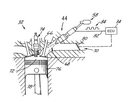
FIGS. 1 & 2 illustrate a fuel delivery system 30 for an
internal combustion engine 32 utilizing an engine control unit
(ECU) 34 that communicates with the engine 32 to control operation
of a fuel pump 36 delivering fuel from a fuel supply 38 to a
plurality of fuel injectors 40 of the engine 32 for directly
controlling fuel pump output to supply at least as much fuel to the
injectors 40 as is being demanded by the engine 32. The ECU 34
monitors actual engine operation and generates an electrical fuel
pump control signal 42, corresponding to engine fuel demand, that
is received by a fuel pump driver circuit 44 which provides
electrical power 46 to the fuel pump to controllably power an
electric motor 48 of the pump 36 in response to the fuel pump
216~8
control signal 42. Advantageously, the fuel pump output is
controlled to provide sufficient fuel to the engine 32 while
minimizing electrical power usage of the fuel pump 36. Further
advantageously, minimizing pump electrical power consumption
enables use of a fuel delivery system 30 of this invention with
systems designed for use without a battery.
The fuel pump 36 in FIG. 1 is an electric motor gear
rotor or turbine fuel pump and is shown installed inside a fuel
tank 52 that contains fuel for being supplied to the engine 32. If
installed inside the tank 52, the pump 36 can be carried by a
bracket (not shown) or received in an in-tank reservoir (also not
shown). However, a fuel delivery system 30 of this invention also
contemplates that the fuel pump 36 may be positioned outside the
tank 52, such as between the engine 32 and tank 36, in the fuel
rail 58, or in a vapor separator (not shown) such as for marine
applications. Examples of some of these types of aforementioned
fuel pump installations are disclosed in U.S. Patent Nos.
5,368,001, 5,263,459, 5,170,764, 5,038,741, 5,096,391, and
4,893,647, also assigned to the assignee hereof and incorporated by
reference herein.
To prevent particulate sediment in the fuel in the tank
52 from being pumped from the tank 52 and damaging the pump 36 or
fouling any fuel injector 40, a filter sock or bag 54 enshrouds the
fuel inlet of the pump 36. To the extent thus far disclosed, pump
36 is similar to those disclosed in U.S. Pat. Nos. 5,149,252, and
5,122,039, assigned to the assignee hereof, incorporated by
reference herein, and to which reference may be had for more
- Z163~88
detailed background discussion of such pump structure and
operation.
As is shown in FIGS. 1 & 2, the pump 36 supplies fuel to
a conduit or fuel line 56 that is connected to a fuel rail 58 at
the engine 32 that enables fuel to be distributed to each injector
40 during engine operation. Preferably, to further prevent fine
dirt and other smaller size particulate matter from reaching any
fuel injector 40, there is a fuel filter 60 downstream of the fuel
pump 36.
Preferably, during engine operation, the fuel pump 36
provides fuel to each injector 40 under a pressure of at least
twenty pounds per square inch (PSI). To maintain adequate fuel
pressure at each injector 40 so each injector 40 precisely meters
sufficient fuel to satisfy engine fuel demand and for efficient
engine operation, the fuel line 56 has a pressure regulator 62
downstream of the fuel pump 36. So that the pressure regulator 62
always provides sufficient fuel to each injector 40 at the desired
pressure for proper injector operation, even in times of heavy
demand, the ECU 34 causes the pump 36 to preferably supply an
amount of fuel to the pressure regulator 62 in excess of that being
demanded by the engine 32.
The fuel delivery system 30 illustrated in FIG. 1 has a
return 64 exten~ing from the pressure regulator 62 to the fuel tank
52 so that excess fuel supplied by the pump 36 can be returned to
the tank 52. Although not shown, the fuel return could be used to
return excess fuel to a vapor separator (not shown), if the engine
is an outboard engine used for marine applications, or the return
~1632~8
could extend from the fuel rail 58 to the tank 52 to return excess
fuel. Alternatively, a returnless fuel injection system may also be
used. If a returnless system is used, preferably the fuel pump has
a pressure relief valve for returning excessively pressurized fuel
from the pump back into the fuel tank. Such a fuel pump is
disclosed in U.S. Patent No. 5,248,223, the disclosure of which is
hereby incorporated by reference.
As is shown more clearly in FIG. 2, during engine
operation and while an intake valve 66 of an engine cylinder 72 is
in an open position during the intake stroke of the cylinder 72, a
metered charge 68 of fuel is sprayed from an injector 40 while it
is open and the fuel mixes with air entering the engine 32 through
the intake manifold 70. This air-fuel mixture enters the cylinder
chamber 72 and is compressed and ignited by a spark emitted by a
spark plug 74 after the intake valve 66 closes. Pressure within the
cylinder chamber 72 dramatically increases upon ignition exerting a
force against an engine piston 76 received in the cylinder 72. This
force is transmitted through a piston rod 78 to a crank (not shown)
that outputs power from the engine 32 to an external component
(also not shown) such as a vehicle transmission, lawn mower blade,
outboard engine propeller, snowmobile track, chain saw chain, weed
whip cutting line or another similar component.
Although a small displacement four-stroke engine is shown
in FIG. 2, having an intake stroke every other engine revolution, a
fuel delivery system 30 of this invention can also be used with a
two-stroke fuel injected internal combustion engine, having an
intake or suction stroke every engine revolution, to vary fuel pump
operation in response to engine fuel demand for reducing electrical
power used by the fuel pump 36. As such, it is preferred that the
fuel delivery system 30 of this invention can be used with fuel
injected two-stroke and four-stroke internal combustion engines.
En~ine Control Unit
The engine control unit (ECU) 34 monitors engine
operation to determine engine fuel demand for varying and
controlling operation of the fuel pump 36 to make at least as much
fuel available to the engine 32 as will be consumed by the engine
32 for closely matching pump operation to fuel demand thereby
increasing pump efficiency and minimizing electrical power usage of
the pump 36. During engine operation, the ECU 34 determines engine
fuel demand preferably by sensing engine speed and sensing or
approximating the amount of air entering the engine 32.
Preferably, engine fuel demand is determined by the ECU
34 by sensing the appropriate engine operating parameters and
selecting the appropriate engine fuel demand or fuel injector
opening duration, based on the value of these parameters, from an
engine control map accessible by the ECU 34 through its software.
Preferably, the engine control map is empirically determined
through routine experimentation and testing and is stored in the
ECU 34, such as in an erasable programmable read only memory
(EPROM) or another such storage device that is accessible by the
ECU 34.
Additionally, other engine operating parameters can also
be sensed or monitored by the ECU 34, such as water temperature,
Z 1 6 ~
ambient air temperature, and engine ignition 74, for adjusting
engine operation as well as determining and/or adjusting engine
fuel demand. For example, the ECU 34 may adjust engine operation by
monitoring engine combustion by communicating with the spark plug
74 and engine fuel demand may based in part on any such engine
operation adjustment made.
Engine fuel demand is used by the ECU 34 to control fuel
pump operation and to control operation of each fuel injector in
metering the appropriate amount of fuel to satisfy demand. The ECU
34 controls fuel injector operation for controlling how much fuel
that each injector 40 should mix with air entering its engine
cylinder chamber 72 by determining how long each injector 40 should
remain open during its intake stroke of engine operation (shown in
FIG. 2) so that a proper air-fuel mixture is achieved for efficient
engine operation. Since the principles of the construction, use and
operation of the fuel delivery system 30 of this invention are the
same for single or multi-cylinder internal combustion engines, only
a small displacement, single cylinder engine will be further
discussed in more detail.
Preferably, for small engine applications, the ECU 34
communicates with the engine 32 to sense the position of its
throttle 80, as is shown in FIG. 2, for determining how much air is
entering the engine 32, and communicates with an engine speed
sensor (not shown) to sense engine speed, all for use in
determining engine fuel demand. Alternatively, to sense the mass of
airflow entering the engine 32, the ECU 34 can communicate with an
airflow sensor or a mass airflow sensor, such as a hot-wire or hot-
3~$
film mass airflow sensor, in determining fuel demand. For example,engine speed can be sensed by the ECU 34 communicating with a
sensor such as a variable reluctance sensor that is in operable
communication with the engine flywheel. Alternatively, engine speed
may be sensed by communicating with the ignition coil of the engine
or through another engine speed sensor.
The ECU 34 uses engine fuel demand to formulate a fuel
injector control signal 82 and thereafter sends the signal 82 to
the injector 40 for controlling the duration of time the injector
40 stays open dispensing fuel during the intake stroke of the
engine 32 so that the proper amount of fuel is dispensed into the
airstream entering the cylinder 72. The signal 82 preferably takes
the form of a pulse width modulated signal 84, such as is depicted
in FIG. 2, with the injector 40 staying open for a duration of time
during the intake stroke corresponding to the width of the pulse of
the signal 84 sent from the ECU 34 to the injector 40. This is also
shown in block schematic form in FIGS. 3 & 4.
Advantageously, also in this manner, the fuel pump
control signal 42 can be formulated at least as quickly as the fuel
injector control signal 82 and, preferably, can be formulated and
communicated to the fuel pump 36 before delivering the fuel
injector control signal 82 to the fuel injector 40, for earlier and
more precisely varying fuel pump output to more closely match
engine fuel demand. As such, fuel pump operation can be more
quickly varied to react to large changes in fuel demand, such as
during wide open throttle (WOT) or substantially full load engine
operating conditions, enabling the amount of excess fuel that must
~163~88
be supplied at virtually all other times of engine operation to
handle such changes in fuel demand to be minimized significantly
decreasing pump power usage.
Preferably, the fuel pump control signal 42 is formulated
so that the fuel pump 36 will supply at least as much fuel to the
fuel injector 40 as the ECU 34 has determined will be consumed by
the engine 32. Preferably, the ECU 34 formulates the fuel pump
control signal 42 by first determining how much fuel the injector
40 will dispense into the engine cylinder 72 during an upcoming
intake stroke of engine operation and multiplies this value by the
engine speed to determine the approximate volumetric flow rate of
the fuel that will be used by the engine 32.
If desired, the ECU 34 can formulate the fuel pump
control signal 42 after or upon the occurrence of a certain number
of engine revolutions, a certain number of intake strokes of engine
operation, a fixed period of time, or a desired angular
displacement of crankshaft rotation. The number of engine
revolutions, intake strokes, time, or amount of rotation between
determining the fuel pump control signal 42 may vary depending upon
engine application, type and speed, as well as other factors.
Preferably, for a multi-cylinder engine, in determining
the fuel pump control signal 42, to determine how much fuel will be
dispensed by each injector 40 during each upcoming intake stroke of
each injector for a preferably predetermined number of engine
revolutions, the ECU 34 sums the duration of time that each
injector 40 is to stay open during its intake stroke. Preferably,
this also corresponds to the sum of how much time the ECU 34 will
2 ~ 8
instruct each fuel injector 40 to stay open through the injector
control signal 82 sent by the ECU 34 for each engine intake stroke
for the predetermined number of engine revolutions. To provide even
quicker response, the ECU 34 can determine engine fuel demand at
smaller increments of engine operation, such as preferably a
fraction of an engine revolution, or a fixed period of time of
engine operation independent of engine revolutions.
Therefore, since the size of the fuel injector 40 is
known and the pressure of the fuel at the injector 40 is regulated
and also preferably known, at least within relatively strict
limits, the volume of fuel that will be needed by the engine 32 and
dispensed by the injector 40 can be determined by the ECU 34 since
it determines how long the injector 40 will stay open dispensing
fuel during its intake stroke. Therefore, engine fuel demand is a
function of the duration of time that the ECU 34 calculates that
the fuel injector 40 is to stay open dispensing fuel during each
intake stroke of engine operation.
If the fuel injector control signal 82 is pulse width
modulated, the ECU 34 can utilize this signal to determine how much
fuel will be dispensed by summing the amount of time the injector
40 will be open during the upcoming intake stroke and thereby at
least substantially simultaneously formulate the fuel pump control
signal 42 so that it controls pump operation to at least replace
the fuel that will be consumed during that intake stroke. If the
fuel injector signal 82 is pulse width modulated, the ECU 34 can
determine the fuel pump control signal 42 by summing the calculated
width of the control pulses that will be sent to each fuel injector
18
21632~8
40 during its upcoming intake stroke to determine the duration of
time the injectors 40 will be open dispensing fuel. Alternatively,
the ECU 34 can independently use the engine fuel demand information
to determine the fuel pump control signal 42.
Preferably, the ECU 34 generates the fuel pump control
signal 42 based upon the following equation:
Fuel Pump Control Signal - (Engine Speed) * (Fuel Duration) * K
where:
Engine Speed is the speed of the engine 32 during the
engine revolution or revolutions or intake
strokes for which the fuel pump control
signal 42 is being calculated and,
preferably, is in revolutions per minute;
Fuel Duration is how long the fuel injectors 40 will stay
open during the desired time period of fuel
pump control signal determination; and
K is a constant to ensure that the fuel pump
control signal 42 causes the fuel pump 36
to supply more fuel than is being demanded
by the engine 32.
Preferably, K, is chosen to ensure that the fuel pump 36 supplies
excess fuel (ie. more fuel than demanded by the engine) so that the
pressure regulator 62 maintains adequate fuel pressure at each fuel
injector 40. Preferably, K, is greater than unity and is chosen so
that the fuel pump 36 supplies at least five-to-ten percent more
fuel than demanded by the engine 32 to maintain adequate fuel
pressure at each injector 40 and make available to the engine 32
sufficient excess fuel to meet fuel demand should fuel demand
suddenly rise. However, K, may be greater or less than five-to-ten
percent depending upon the engine type, engine application, fuel
19
21632~8
pump size and type and other design criteria. For example, K, may
be selected or empirically determined based upon the type and size
of fuel pump and intended engine application so that a specific
desired amount of excess fuel is supplied to the engine during
operation. Preferably, K, is determined by calibrating the fuel
delivery system 30 by monitoring fuel flow to the injectors 40 and
varying K until the fuel pump 36 is delivering the desired amount
of fuel in excess of the fuel required by the engine 32.
Fuel PumP Driver
The fuel pump driver 44 provides electrical power 46 to
the motor 48 of the fuel pump 36 in response to the fuel pump
control signal 42 provided to the driver 44 by the ECU 34.
Preferably, the fuel pump driver 44 provides electrical power 46 to
the fuel pump 36 in proportion to the fuel pump control signal 42
to vary the duty cycle of fuel pump operation in response to the
fuel requirements of the engine 32 as communicated to it by the
fuel pump control signal 42. Typically, during normal engine
operation, the fuel pump driver 44 applies an electrical potential
to the fuel pump 36 of preferably between twelve to fifteen volts.
As is depicted in FIGS. 3 ~ 4, the fuel pump driver 44 is
preferably located nearby the fuel pump 36 to minimize the distance
the electrical pump power signal 46 must travel to reach the motor
48 for minimizing the generation of electromagnetic interference
during operation as well as minimizing the susceptibility of the
signal to electromagnetic and radio frequency interference from
2163288
other sources. Preferably, the fuel pump driver 44 is carried by
the pump 36.
As is shown more clearly in FIG. 4, the fuel pump driver
44 preferably has a pulse width modulated signal amplifier 86 for
generating a pulse width modulated fuel pump power signal 88 and
delivering the power signal 88 to the fuel pump motor 48 for
driving the pump 36. Preferably, the number and width of pulses
during each unit of time of operation is proportional to the fuel
pump control signal 42 received from the ECU 34 so that the duty
cycle of pump operation is accurately controlled in response to the
fuel pump control signal 42 thereby also accurately controlling
fuel flow to the engine 32. Therefore, the pulse width modulated
fuel pump power signal 46 is a duty cycle signal that controls
operation of the fuel pump 36 in response to the fuel pump control
signal 42. Preferably, the fuel pump control signal 42 is also a
pulse width modulated signal 90 that controls the duty cycle of
pump operation by controlling the power signal 88 issued by the
fuel pump driver 44 to the pump motor 48.
To ensure that the fuel pump 36 is always running to
avoid any time lag in fuel delivery associated with overcoming
inertia of the pump components during an increase in fuel demand
and to ensure that there is excess fuel being supplied for the
injectors 40 to handle sudden increases fuel demand, after being
calculated by the ECU 34, the control signal 42 is automatically
set by the ECU 34 so that the pump 36 preferably operates at a
minimum duty cycle should the calculated fuel pump control signal
equation previously discussed produce a result less than a minimum
21632~8
signal limit that would otherwise cause the pump 36 to operate at
less than the minimum duty cycle. Preferably, the ECU 34
continually compares the calculated fuel pump control signal value
to the minimum duty cycle limit and sets the fuel pump control
signal 42 equal to the minimum duty cycle limit should the
calculated result be less than the minimum limit. Therefore, for
example, during periods of sufficiently low fuel demand, the
control signal 42 is preferably set to cause the fuel pump 36 to
operate at a duty cycle of preferably fifty percent.
However, this minimum duty cycle limit may be adjusted
upwardly or downwardly depending upon the size and type of fuel
pump as well as other operating factors that may need to be
empirically determined. For example, future fuel pump developments
may enable gear-rotor type fuel pumps to efficiently operate at
duty cycles of much less than fifty percent. For turbine-type fuel
pumps, the minimum duty cycle can be considerably lower; as low as
a thirty percent duty cycle or lower.
Conversely, the ECU 34 will set the fuel pump control
signal 42 to that which will cause the pump 36 to operate at a one-
hundred percent duty cycle should the calculated control signal
result (see equation above) produce pump operation at greater than
one-hundred percent duty cycle for preventing too large of a power
signal 46 to be sent to the pump 36. Otherwise, if the calculated
control signal result would produce pump operation between a fifty
and one-hundred percent duty cycle the fuel pump control signal 42
is set equal to the calculated value. After calculation and, if
necessary, duty cycle adjustment, the fuel pump control signal 42
~1 ~ 32~
is applied to the fuel pump driver 44 causing the driver 44 to
operate the pump 36 at a duty cycle set by the control signal 42.
Second Preferred Embodiment
FIGS. 5 & 6 illustrate a second preferred embodiment of a
fuel delivery system 30' of this invention. Fuel delivery system
30' is the same as the fuel delivery system 30 shown in FIGS. 1, 3
& 4, except that the fuel pump driver 44 is combined with the ECU
34 in a single unitary package 92, such as a circuit board module
having a common circuit board or the like, to minimize the number
of parts of the fuel delivery system required for assembly.
Preferably, the fuel pump power signal 46 is delivered to the fuel
pump motor 48 using coaxial cable to minimize pickup and generation
of electromagnetic interference. As is shown more clearly in FIG.
6, the fuel pump control signal is preferably delivered from the
ECU 34 directly to the fuel pump driver 44. Preferably, the fuel
pump driver 44 has a pulse width modulated amplifier 86 to provide
a pulse width modulated fuel pump power signal 88 to drive the
motor 48 of the fuel pump 36.
Use and O~eration
In use and operation of the fuel delivery system of this
invention, as is shown by the flowchart diagram in FIG. 7, at
startup 100, during a revolution of engine operation and preferably
for each or every other revolution of, respectively, two-stroke or
four-stroke engine operation, the ECU 34 determines the engine
speed 102 and the duration of time each fuel injector is to stay
open during the engine revolution 104 by determining fuel demand.
~16328~
Preferably, the ECU 34 determines fuel demand by reading the
position of the throttle 80 and sensing engine speed.
Upon determining engine speed and fuel demand, the fuel
pump control signal 42 is calculated using the previously discussed
equation 106:
Fuel Pump Control Signal ~ (Engine Speed) * (Fuel Duration) * K
If the calculated fuel pump control signal would produce a pump
duty cycle that is greater than the maximum duty cycle 108 of the
fuel pump 36, preferably a one-hundred percent duty cycle, the fuel
pump control signal 42 is set so that the pump 36 operates at the
maximum duty cycle and this signal 42 is applied 112 to the fuel
pump driver 44 causing the pump 36 to operate at the maximum duty
cycle. If the calculated fuel pump control signal would produce a
pump duty cycle that is less than a desired minimum duty cycle 114
of the pump 36, such as a fifty percent duty cycle, the fuel pump
control signal 42 is set 116 so that the pump 36 operates at the
desired minimum duty cycle and this fuel pump control signal is
applied 112 to the fuel pump driver 44 causing the fuel pump 36 to
operate at the desired minimum duty cycle. Should the calculated
fuel pump control signal produce a fuel pump-duty cycle between the
desired minimum and maximum duty cycle of the fuel pump 36, the
fuel pump control signal 42 will be set equal to the calculated
value and applied 112 to the fuel pump driver 44 causing the driver
44 to send the corresponding drive signal 46 to the fuel pump 36.
24
- 2163288
While the present invention has been disclosed in
connection with the preferred embodiments thereof, it should be
understood that there will be other embodiments which fall within
the spirit and scope of the invention and that the invention is
susceptible to modification, variation and change without departing
from the scope and fair meaning of the following claims.