Language selection

Search

Patent 2163412 Summary

Third-party information liability

Some of the information on this Web page has been provided by external sources. The Government of Canada is not responsible for the accuracy, reliability or currency of the information supplied by external sources. Users wishing to rely upon this information should consult directly with the source of the information. Content provided by external sources is not subject to official languages, privacy and accessibility requirements.

Claims and Abstract availability

Any discrepancies in the text and image of the Claims and Abstract are due to differing posting times. Text of the Claims and Abstract are posted:

  • At the time the application is open to public inspection;
  • At the time of issue of the patent (grant).
(12) Patent: (11) CA 2163412
(54) English Title: MACERATOR
(54) French Title: POMPE DILACERATRICE
Status: Deemed expired
Bibliographic Data
(51) International Patent Classification (IPC):
  • B02C 18/06 (2006.01)
  • B02C 18/14 (2006.01)
(72) Inventors :
  • STEVENSON, CHRISTOPHER (United Kingdom)
(73) Owners :
  • MONO PUMPS LIMITED (United Kingdom)
(71) Applicants :
  • MONO PUMPS LIMITED (United Kingdom)
(74) Agent: NORTON ROSE FULBRIGHT CANADA LLP/S.E.N.C.R.L., S.R.L.
(74) Associate agent:
(45) Issued: 2002-02-05
(22) Filed Date: 1995-11-21
(41) Open to Public Inspection: 1996-05-24
Examination requested: 1998-03-27
Availability of licence: N/A
(25) Language of filing: English

Patent Cooperation Treaty (PCT): No

(30) Application Priority Data:
Application No. Country/Territory Date
9423623.9 United Kingdom 1994-11-23

Abstracts

English Abstract

A macerator (32), e.g. for sewerage, including two stacks of interleaved contra-rotating cutters and spacers is mounted in a macerator chamber (30) having an inlet (60) and an outlet (62). The chamber (32) has a sump (80) upstream of the stacks of the cutters, which are mounted at such an angle that hard, solid material such as stones and metal fall under gravity through the influent into the sump.


French Abstract

Un désintégrateur (32) par exemple pour un système d'assainissement, comprenant deux empilements contrarotatifs de lames et d'espaceurs intercalés, est monté dans une chambre de désintégration (30) présentant une entrée (60) et une sortie (62). La chambre (32) présente un collecteur (80) en amont des empilements de lames, qui sont montés selon un angle tel que les matières solides et dures telles que des pierres et du métal tombent sous l'effet de la gravité dans l'influent jusque dans le collecteur.

Claims

Note: Claims are shown in the official language in which they were submitted.


5
The embodiments of the invention in which an exclusive
property or privilege is claimed are defined as follows:
1. A macerator comprising a macerating chamber, an
inlet and an outlet to said chamber for the inflow of
material to be macerated and the outflow of macerated
material, respectively, side walls of said chamber, a
macerator stack mounted in said chamber, said macerator
stack comprising first and second parallel contra-rotating
shafts extending through said chamber between said side
walls, a plurality of alternate cutters and spacers of the
same nominal axial thickness mounted on each of said first
and second shafts, to form a stack, the cutters of the first
shaft being interleaved with those of the second shaft, at
least one tooth formed on each cutter, each tooth having a
front cutting face, the portion of the macerator chamber
between the inlet and the macerator stack forming an inlet
chamber, said parallel shafts having axes included in a
plane which is inclined at an angle to the horizontal, with
the upper part of the plane nearer to the inlet than the
lower part of the plane and a sump forming a lower part of
said inlet chamber, said sump being at a location directly
below the inclined macerator stack within the macerator
chamber, effective to cause relatively heavy solid material
to be caused to drop or be rejected by the cutters and drop
into the sump, whereby it does not pass into the cutters
with the remainder of the inflowing material.

Description

Note: Descriptions are shown in the official language in which they were submitted.


CA 02163412 1998-OS-28
1
MACERATOR
The present invention relates to macerators.
Various forms of macerators have been proposed, for example
for inclusion in a sewerage treatment line. An early and
relatively simple form is that disclosed in GB-A-1569672 in
which the macerator comprises a macerating chamber,
including an inlet and an outlet for inflow of material to
be macerated and the outflow of macerated material, side
walls of said chamber, first and second parallel contra-
rotating shafts extending through said chamber between said
side walls, a plurality of alternate cutters and spacers of
the same nominal axial thickness mounted on each of said
first and second shafts, to form a stack, the cutters of the
first shaft being interleaved with those of the second shaft
and comprising at least one tooth. In this structure the
teeth are symmetrical, the idea being that the cutters can
be turned round when the leading edges wear.
A modified version of such a structure is
disclosed in EP-A-0454922 in which a rather different type
of cutter is disclosed providing improved results.
A further improvement is shown in EP-A-0532145 in
which the side rail, which may be incorporated in the
macerator chamber, is provided with angled slots to
facilitate the passage of excess fluid and yet prevent the
passage of relatively thin material, such as plastics films
or the like.
One problem which can occur with all these
arrangements when used in a sewerage treatment line, is that
sometimes very hard solid materials, such as stones, pieces
of metal etc. do get entrained, particularly when storm
water is involved. These can have a very damaging effect on
the cutters and can cause seizure of the macerator.
It is now proposed, according to the present
invention, to provide a macerator comprising a macerating


CA 02163412 1998-OS-28
2
chamber, an inlet and an outlet to said chamber for the
inflow of material to be macerated and the outflow of
macerated material, respectively, side walls of said
chamber, a macerator stack mounted in said chamber, said
macerator stack comprising first and second parallel contra-
rotating shafts extending through said chamber between said
side walls, a plurality of alternate cutters and spacers of
the same nominal axial thickness mounted on each of said
first and second shafts, to form a stack, the cutters of the
first shaft being interleaved with those of the second
shaft, at least one tooth formed on each cutter, each tooth
having a front cutting face, the portion of the macerator
chamber between the inlet and the macerator stack forming an
inlet chamber, said parallel shafts having axes included in
a plane which is inclined at an angle to the horizontal,
with the upper part of the plane nearer to the inlet than
the lower part of the plane and a sump forming a lower part
of said inlet chamber, said sump being at a location
directly below the inclined macerator stack within the
macerator chamber, effective to cause relatively heavy solid
material to be caused to drop or be rejected by the cutters
and drop into the sump, whereby it does not pass into the
cutters with the remainder of the inflowing material.
Such a structure enables the more heavy materials,
such as stones, pieces of metal etc. to drop under gravity
through the influent, which is usually not very viscous,
into the sump where it can, from time to time, be removed by
the provision of a suitable closeable discharge opening.
These hard materials therefore do not find their way into
the cutter bank of the macerator and therefore the problem
of damage to these cutters is alleviated. If some hard
materials do reach the cutters they will be rejected and
drop into the sump.
In order that the present invention may more
readily be understood, the following description is given


CA 02163412 2001-03-20
3
Merely by way of non-limitative example with reference to the
accompanying drawings, in which:-
Figure 1 is a side elevation of a known form of macerator as
disclosed in EP-A-0532145;
Figure 2 is a reduced cross-section on a plane perpendicular
to the axes of the stacks showing the relative position of the side rail ribs
and slots of the cutters; and
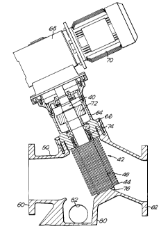
Figure 3 shows an arrangement of macerator according to
the present invention.
If reference is first made to Figure 1, two shafts 40 are
shown mounted above parallel axes and each carries a macerator stack 42
comprising a plurality of cutters 44 alternating with spacers 46, the cutters
and spacers being of the same thickness. There is an axial displacement
of the cutters on one shaft as compared with those on the other, so that the
cutters are interleaved one with the other. Side walls, which in this
embodiment are in the form of side rails 30 are located adjacent each
stack of cutters and includes upper and lower chamfered faces 30a, 30b
and angled ribs 32 defining slots 34 therebetween, the ribs 32 ensuring
that liquid borne solid material flowing through a slot crosses a plane of at
least two cutting elements 44. Each cutter 44 of a stack includes five
teeth 48 and each tooth has a front cutting face 48a and a tip of which
three 49a, 49b and 49c can be seen in Figure 1. Crossing the plane of
several cutting elements increases the likelihood that a piece of solid
material which might have passed down one of the slots 34 will contact
the cutting elements 44 several times and be adequately reduced to a
manageable particle size.
This is shown more clearly in Figure 2. In the embodiment
shown therein. The left-hand shaft 40 (Figure 2) rotates clockwise and
the right-hand shaft anticlockwise and hence material is fed vertically
downwardly, that is to say


CA 02163412 1998-OS-28
4
the inlet is at the top. This is a fairly standard
orientation and has the problems enumerated above.
As can be seen in Figure 3, according to the
invention, the casing 50 is provided with a horizontal inlet
60 and a horizontal outlet 62 on opposite sides of the stack
42. The upper surface of the housing 50 is angled at about
30° to the horizontal and a pull back bearing housing 64 is
retained in place by a bolt 66 so that the axis of the
shafts 40 are at an angle of 60° to the horizontal. This
angle can vary between 40° and 70°.
One of the two shafts 40 is driven via a gear box
68 which in turn has its drive provided by a motor 70 and
rotation of the other of the two shafts is effected by
transfer gears 72 in the form of a close ratio gear set to
give the driven shaft the correct differential speed to the
drive shaft.
Mechanical seals 74 are provided, two per machine
only, which provide a very adequate seal. It will be noted
that the lower end of the main shafts 40 abut an inclined
portion 76 of the housing and hence the main shaft is
cantilevered downwardly thereby eliminating the need for
bottom seals and bearings.
The lower part of the housing 50 is provided with
a sump 80, on the inlet side of the stack 42 and rejected
objects can be removed via clean-out ports indicated by the
reference numeral 82.
Material to be macerated is introduced via a
pipeline at 60 and flows through the stack of cutters 42 to
macerated thereby and the resulting macerated material exits
through the outlet 62 to a suitable location.
Rather heavy materials such as stones, pieces of
metal etc., which would normally damage the macerator
cutters, fall under gravity into the sump 80 and can readily
be removed.
.r'~.

Representative Drawing
A single figure which represents the drawing illustrating the invention.
Administrative Status

For a clearer understanding of the status of the application/patent presented on this page, the site Disclaimer , as well as the definitions for Patent , Administrative Status , Maintenance Fee  and Payment History  should be consulted.

Administrative Status

Title Date
Forecasted Issue Date 2002-02-05
(22) Filed 1995-11-21
(41) Open to Public Inspection 1996-05-24
Examination Requested 1998-03-27
(45) Issued 2002-02-05
Deemed Expired 2015-11-23

Abandonment History

There is no abandonment history.

Payment History

Fee Type Anniversary Year Due Date Amount Paid Paid Date
Application Fee $0.00 1995-11-21
Registration of a document - section 124 $0.00 1996-02-15
Maintenance Fee - Application - New Act 2 1997-11-21 $100.00 1997-10-30
Request for Examination $400.00 1998-03-27
Maintenance Fee - Application - New Act 3 1998-11-23 $100.00 1998-10-29
Maintenance Fee - Application - New Act 4 1999-11-22 $100.00 1999-10-29
Maintenance Fee - Application - New Act 5 2000-11-21 $150.00 2000-10-31
Maintenance Fee - Application - New Act 6 2001-11-21 $150.00 2001-10-29
Final Fee $300.00 2001-11-05
Maintenance Fee - Patent - New Act 7 2002-11-21 $150.00 2002-10-17
Maintenance Fee - Patent - New Act 8 2003-11-21 $150.00 2003-10-16
Maintenance Fee - Patent - New Act 9 2004-11-22 $200.00 2004-10-07
Maintenance Fee - Patent - New Act 10 2005-11-21 $250.00 2005-10-06
Maintenance Fee - Patent - New Act 11 2006-11-21 $250.00 2006-10-06
Maintenance Fee - Patent - New Act 12 2007-11-21 $250.00 2007-10-09
Maintenance Fee - Patent - New Act 13 2008-11-21 $250.00 2008-10-20
Maintenance Fee - Patent - New Act 14 2009-11-23 $250.00 2009-10-14
Maintenance Fee - Patent - New Act 15 2010-11-22 $450.00 2010-10-25
Maintenance Fee - Patent - New Act 16 2011-11-21 $450.00 2011-10-13
Maintenance Fee - Patent - New Act 17 2012-11-21 $450.00 2012-10-10
Maintenance Fee - Patent - New Act 18 2013-11-21 $450.00 2013-10-09
Owners on Record

Note: Records showing the ownership history in alphabetical order.

Current Owners on Record
MONO PUMPS LIMITED
Past Owners on Record
STEVENSON, CHRISTOPHER
Past Owners that do not appear in the "Owners on Record" listing will appear in other documentation within the application.
Documents

To view selected files, please enter reCAPTCHA code :


To view images, click a link in the Document Description column. To download the documents, select one or more checkboxes in the first column and then click the "Download Selected in PDF format (Zip Archive)" or the "Download Selected as Single PDF" button.

List of published and non-published patent-specific documents on the CPD .

If you have any difficulty accessing content, you can call the Client Service Centre at 1-866-997-1936 or send them an e-mail at CIPO Client Service Centre.


Document
Description 
Date
(yyyy-mm-dd) 
Number of pages   Size of Image (KB) 
Abstract 1996-04-01 1 12
Description 1996-04-01 4 190
Drawings 2001-03-20 3 97
Cover Page 1996-04-01 1 16
Representative Drawing 2002-01-07 1 19
Description 1998-05-28 4 190
Claims 1998-05-28 1 38
Drawings 1998-05-28 3 97
Claims 1996-04-01 1 39
Drawings 1996-04-01 4 110
Description 2001-03-20 4 188
Cover Page 2002-01-07 1 42
Representative Drawing 1998-03-18 1 40
Prosecution-Amendment 2000-09-26 2 37
Prosecution-Amendment 1999-07-30 2 44
Prosecution-Amendment 2001-03-20 6 202
Assignment 1995-11-21 7 215
Prosecution-Amendment 1998-03-27 11 365
Correspondence 2001-11-05 2 48