Note: Descriptions are shown in the official language in which they were submitted.
. 2163632
' High Efficiency Mixer For Mixing Pulp Material
And Treatment Substances
The invention refers to a mixer, particularly a high-efficiency mixer for
fluffing
shredded pulps and mixing them with treatment substances and/or additives,
particularly bleaching chemicals. Said mixer contains an annular mixing and
fluffing
zone, located between a disc rotor and an annular stator, and a central
material feed
channel in which a positive conveyor is located for conveying purposes.
Mixers are described in, for example, AT-PS 388 193 and show a material feed
channel in the form of a vertical chute, where the annular mixing and fluffing
zone is
located accordingly on a horizontal plane and the treated material is carried
off to the
side. The throughput of these mixers is limited because the diameter of the
chute
cannot be selected at will.
Also described in CH-PS 485 479 is a device for creating dispersions or
solutions
from a liquid component .and a solid or pasty component using a mixing
apparatus.
To achieve this the solid or pasty component is fed to the mixing apparatus
through a
conveying screw which ends directly in front of the rotor of the mixing
apparatus and
the liquid component, on i:he other hand, is discharged from a feed pipe at
the end of
the conveying screw. If this configuration is used to mix fibrous pulps with
treatment
substances, e.g. bleaching chemicals, the result would be inadequate
conveying, on
the one hand, since the material does not fill the conveying screw and uneven
penetration of the fibrous pulps on the other hand.
The invention thus suggests that the positive conveyor be designed as a ribbon
feeder and, on the one hand, that a baffle, in particular a baffle shaped like
the
envelope of a cone, that is firmly connected to the shaft of the ribbon feeder
be
provided at the end of thE: shaft of the ribbon feeder or, on the other hand,
a double
casing be provided roundl the ribbon feeder. Thus, the ring of fibrous pulp
forming
round the circumference of the pulp feed channel can be guided particularly
well, and
the feed and even distribution of treatment substances, particularly bleaching
chemicals, in liquid form on the one hand and in gaseous form on the other
hand, is
guaranteed in the vicinity of the mixing and fluffing zone.
This design also permits the possibility of a plant with a horizontal material
feed
channel and appropriate vertical arrangement of the mixing and fluffing zone
in which
the rotor and stator are mounted at right angles to the horizontal. A slanting
arrangement is thus also possible.
1
~~s~s~
In those mixer designs already known, additives, particularly bleaching
chemicals,
are dosed into the chute, for example, where problems can occur with even
distribution of the additives through the material, particularly if liquid
additives are
used. In the case of pulp; it is well known''-that its high capacity for
adsorption makes
liquid additives difficult to distribute if the pulp is not saturated. In
addition, there is
also the problem of non-uniform retention time and uneven reaction process
since
the aim is that the additives (only) take their full effect in the mixing and
fluffing zone
sector.
Positioning a positive conveyor in the feed channel now opens up the
possibility of
feeding the treatment substances and/or the additives centrally through the
positive
conveyor itself, thus the invention suggests that the positive conveyor is
provided for
feeding of treatment subsi:ances and/or additives and shows, in particular, an
axial
hollow shaft through which the treatment substances and/or additives can be
dosed.
In this case, for example, the hollow shaft of the positive conveyor can
contain
outlets along its entire length or in selected sections thereof, preferably,
above all, at
the end facing the mixing and fluffing device, i.e. as near as possible to the
disc
rotor.
The hollow shaft can servE: to feed in various additives, e.g. to feed in gas
over the
entire length of the shaft and/or to feed in liquid at the end of the shaft,
whereby at
least one separate pipe being included in the shaft for feeding in treatment
substances and/or additivEa may be provided. Such a pipe is easy to change and
can be removed for cleaning. This cleaning facility is important if, for
example,
silicate is added in a peroxiide bleaching process.
In order to achieve good diistribution of the additives added at the end of
the positive
conveyor before they come into contact with the material and to establish such
contact as close to the mixing and fluffing zone as possible, it is suggested
that a
baffle, particularly a baffle shaped like the envelope of a cone be mounted at
the end
of the positive conveyor next to the mixing and fluffing zone and that this
baffle
should deflect the solids towards the periphery of the material feed channel,
with said
at least one opening beings provided, particularly on the side of the baffle
facing the
mixing and fluffing zone.
Furthermore, the invention suggest to this end that said at least one opening
has a
discharge direction which runs at least generally parallel to the side of the
baffle.
Thus, the treatment substances and/or additives are guided towards the mixing
and
fluffing zone. A further possible configuration of the mixer is to place the
positive
2
216332
conveyor in a feed channel with a double casing and use the interspace between
the
two walls of the casing to feed gases and/or vapours to the mixing and
fluffing zone.
In this case the double G~sing can include a deflector rim at the end nearest
the
mixing and fluffing zone which deflects gases and/or vapours tovi~ards the
mixing and
fluffing zone. The interspace can also have an extension at the end facing the
mixing and fluffing zone.
With the mixer according too the invention it is possible to obtain optimum
distribution
of the treatment substances and/or additives in the pulp, as well as to
achieve
contact as close as possible to the mixing and fluffing zone. The positive
conveyor
can be cleaned easily.
The mixer according to thE: invention is intended particularly for treatment
of fibrous
material. By way of example, the starting material, e.g. groundwood, TMP or
CTMP,
is pre-dewatered on a wire belt press, usually a double wire belt press,
shredded in a
shredder and then fed to i:he mixer inlet by a conveyor screw. After going
through
the mixer, the pulp is transported to a bleaching tower and is removed from
there as
bleached pulp.
.-
2a
2163632
With the mixer according vto the invention a shredded pulp web is broken down
into
single fibres to a large extent. Due to the large fibre surface the bleaching
agent,
which can be applied either as a solution or in gaseous form, e.g. ozone,
penetrates
the fibres quickly and evenly. The mixing process does not cause any change in
the _ _
fibre fraction. By adding l:he chemicals immediately before the rotor, the
chemicals
do not take effect on the fibres until this point, where they are present as
more or
less single fibres, thus considerably enhancing the efficiency of the
(bleaching)
process. As a result, the retention time of the pulp can be reduced both in
the mixer
and in the bleaching tower, thus making a higher throughput possible.
In the following the inventiion is explained in more detail using two
different designs
of a mixer according to the invention and referring to the drawing in which
the same
components have the same reference markings and in which fig. 1 shows sections
of
a mixer with chemical feed through the hollow shaft of the positive conveyor
and fig.
2 sections of a mixer with chemical feed via the double casing of the pulp
feed
channel.
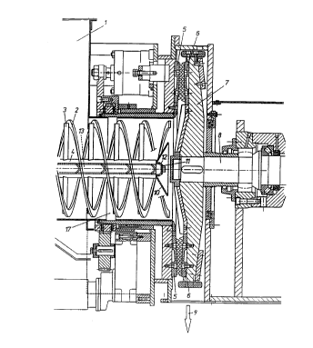
Fig. 1 shows a longitudinal section through a mixer according to the invention
in
which the pulp to be fluffed and bleached is fed in through inlet 1 and
positively
conveyed to the pulp feed channel 17 by a ribbon feeder 2. The screw flights
of the
ribbon feeder 2 are attached to a hollow shaft 4 by struts 3. The pulp is fed
to the
rotor 7 centrally by the ribbon feeder 2 and brought in between the grinding
segments 5 on the stator side and the grinding segments 6 on the rotor side.
Due to
the rotating movement by the rotor shaft 8 the pulp fibres are mixed and
fluffed
between the segments 5, 6 and permit the bleaching chemicals added to
penetrate
the pulp completely and thus, to bleach it fully. The pulp is then discharged
again at
9 and fed to a further treatment stage or the bleaching reaction is completed
in a
subsequent bleaching tower.
The bleaching agent is added to the rotor 7 through the hollow shaft 4 of the
ribbon
feeder 2. Peroxide, for example, is fed through the inner chamber 13 of the
hollow
shaft 4 to a discharge facility 11 which closes off the end of the hollow
shaft 14 and
contains openings, preferably drill holes 12. This discharge facility 11 is
mounted in
the conveying direction behind a baffle 10 shaped like the envelope of a cone.
The
conic frustum opens here ipointing in the direction of the rotor 7. Due to the
rotating
movement of the hollow shaft 4 the bleaching chemicals are guided by the
centrifugal force towards the inner side of the baffle 10, which is assisted
by the
orientation of the axes of the drill holes 12 in the direction of the
generatrix of the
conical envelope. At the end of the baffle 10 facing the rotor 7 the chemicals
are
3
263632
then distributed evenly over the circumference and thus brought close to the
mixing
and fluffing zone between the segments 5 and 6.
Fig. 2 illustrates a variant for gaseous bleaching chemicals in which the
chemicals,
e.g: ozone, are fed through a feed pipe 14 to a ring slot 15 formed by a
double
casing of the material feed channel 17. At the channel end facing the rotor 7
the
channel has a widening and/or a deflection rim 16 enabling the chemicals to be
brought in with as even a distribution as possible and close to the mixing and
fluffing
zone 5, 6.
The invention is not limited to the designs illustrated, with other designs .
of
distribution device, in parl:icular, being conceivable, and the characteristic
features
shown in figures 1 and 2 pan also be realised in combination.
, .-
4