Note: Descriptions are shown in the official language in which they were submitted.
2163752
Title of the Invention
ORAL HYGIENE INSTRUMENT
Technical Field
This invention relates to a portable oral hygiene
instrument such as an electric interdental brush, an electric
toothbrush or an electric gum massager.
Backqround Art
Various electric toothbrushes and electric interdental
cleaning brushes which have an interdental cleaning brush or
a toothbrush removably attached to one end of a substantially
cylindrical holder member and an electric motor and a battery
for powering the same mounted inside the holder member and
have the other end of the holder member watertightly sealed
by a cap member and have an eccentric weight fixed to the
rotary shaft of the electric motor and vibrate the
interdental cleaning brush by way of the holder member with
vibration generated by rotation of the eccentric weight have
been proposed.
Because electric toothbrushes and electric interdental
cleaning brushes are usually used in bathrooms and the like
they are required to be watertight, and in their
construction, for example as shown in Fig. 28, a female
thread portion 103 of a cap member 102 is screwed onto a male
21~3~S2
thread portion 101 of a holder member 100, a seal ring 104 is
fitted around the base of the male thread portion 101, and by
the cap member 102 being screwed onto the holder member 100
the seal ring 104 is pressed upon by the end of the cap
member 102 and the gap between the holder member 100 and the
cap member 102 is sealed; to supply electricity to an
electric motor, the positive pole of a battery 105 is
directly connected to one of the terminals of the electric
motor and the other terminal of the electric motor is
extended by way of a bandlike wiring plate 106 or the like to
the vicinity of an opening in the holder member 100, the
negative pole of the battery lOS is connected to a spring
terminal 107 mounted in the cap member 102, a bandlike
connecting plate 108 connected to the spring terminal 107 is
mounted between the wiring plate 106 and the circumferential
wall of the holder member 100 and electrically connects the
spring terminal 107 to the wiring plate 106, a switch is
interposed in this supply circuit and the motor is operated
by operating the switch.
However, with the kind of electric toothbrush or
electric interdental cléaning brush described above, because
even when the cap member has become somewhat loose the supply
circuit is closed and if the switch is operated the electric
motor will operate, there has been the problem that the
instrument is sometimes used without it being noticed that
2163~52
the cap member is loose and water or the like gets inside the
holder member and corrodes the electric motor and the battery
and the wiring, etc.
Also, after the switch is turned OFF without it being
noticed that the cap member is loose, the whole device is
sometimes washed in order to clean it or is just left with
toothbrushing water still on it. At such times, as well as
water getting in and corroding the wiring plate and the
electric motor and the battery, eventually causing the
instrument to break down, the problem has occurred that
hardening of the toothbrushing water causes the thread
portion of the cap member to get stuck, whereupon the cap
member cannot be opened and closed.
Also, in the electric interdental cleaning brush
described above, because a spring terminal is mounted on the
cap member side and for example a disclike fixing member
having a claw portion on its upper surface is provided and
with a base portion of the spring terminal held by the claw
portion of the fixing member the spring terminal and the
fixing member are fitted and fixed to the inner bottom
portion of the cap member together, the number of parts
increases and installation of the spring terminal in the cap
member is extremely complicated.
In order to removably attach an oral hygiene tool such
as a toothbrush or an interdental cleaning brush to the
21637~2
holder member the oral hygiene tool is usually provided with
a shaft portion and a fitting hole is formed in one end of
this shaft portion and the oral hygiene tool is removably
attached to the holder member by this fitting hole being
fitted over a projecting portion formed on the holder member,
or the oral hygiene tool is removably attached to the holder
member by the base portion of the shaft portion being plugged
into a bottomed cylindrical holding portion formed in the
holder member. Also, sometimes a plurality of axial slits
are formed in the holding portion so that the end of the
holding portion can expand and contract radially and absorb
dimensional errors in the outer diameter of the shaft portion
and also so that toothpaste powder adhered to the inner back
surface of the holding portion can be easily cleaned off.
However, when slits are thus provided in the holding portion,
if the slits are made long the force with which the shaft
portion is held decreases; consequently it is problematic to
have the slits extending as far as the vicinity of the inner
back surface of the holding portion and even when slits are
provided it cannot be said that toothpaste powder adhered to
the inner back surface of the holding portion can be
sufficiently effectively cleaned off.
An object of this invention is to provide an oral
hygiene instrument in which incursion of water and the like
into the holder member due to looseness of the cap member is
2163752
completely prevented, installation of the spring terminal is
simplified, and, while maintaining sufficient strength of
attachment of the oral hygiene tool to the holding member,
cleaning of the inner back surface of the holding member is
easy.
Disclosure of the Invention
An oral hygiene instrument according to claim
comprises: a holder member capable of accommodating a battery
and provided with a holder side thread portion at a first end
and watertightly closed at a second end; an oral hygiene tool
removably attached to the second end of the holder member and
comprising a toothbrush or an interdental cleaning brush or
a gum massaging tool or a nipple-type gum massaging tool
mounted on the end of a shaft portion; vibration generating
means housed in the second end of the holder member for
vibrating the oral hygiene tool by way of the holder member;
a cap member having a cap side thread portion meshing with
the holder side thread portion which cap member is removably
attached to the first end of the holder member and closes an
opening in the first end of the holder member; a seal ring
fitted on a portion of the holder member or the cap member at
the external end of the part where the two members mesh which
seal ring is pressed upon by either the cap member or the
holder member and seals the gap between the holder member and
2163~2
the cap member within a range of a predetermined angle of
screwing of the cap member with respect to the holder member
from a late stage to completion of said screwing; and a
holder side contact piece and a cap side contact piece
mounted in the holder member and the cap member respectively
which approach each other when the cap member is screwed with
respect to the holder member and in the range of the
predetermined angle make contact and close a circuit
supplying electricity to the vibration generating means.
In an oral hygiene instrument according to claim 1,
within the range of the predetermined angle of screwing of
the cap member with respect to the holder member from the
late stage to the completion of said screwing the seal ring
fitted on the holder member or the cap member is pressed upon
by the cap member or the holder member and the gap between
the holder member and the cap member is sealed, and in this
range of the predetermined angle the holder side contact
piece mounted on the holder member makes contact with the cap
side contact piece mounted on the cap member and the circuit
supplying power to the vibration generating means is thereby
closed and an electric motor or the like of the vibration
generating means is driven and the oral hygiene tool is
vibrated by way of the holder member. That is, because until
the cap member is screwed with respect to the holder member
as far as the range of the predetermined angle and the gap
2163~52
between the holder member and the cap member is sealed with
certainty by the seal ring the supply circuit cannot be
closed and the electric motor or the like cannot be driven,
and as a result it is made known to the user that sealing is
not being effected properly and the instrument can never be
used with the seal in an improper state.
Also, because the seal ring is fitted on a portion of
the holder member or the cap member at the external end of
the part where the two members mesh, the incursion of
toothbrushing water or the like into where the holder member
and the cap member mesh is prevented with certainty.
An oral hygiene instrument according to claim 2 is an
instrument according to claim 1 wherein the holder side
contact piece and the cap side contact piece constitute a
switch of the supply circuit, and the supply circuit is
opened and closed by the cap member being turned in the range
of the predetermined angle.
In an oral hygiene instrument according to claim 2, by
turning the cap member within the range of the predetermined
angle, the supply circuit can be opened and closed with the
gap between the holder member and the cap member sealed with
certainty.
An oral hygiene instrument according to claim 3 is an
instrument according to claim 1 wherein a switch for opening
and closing the supply circuit is provided in the holder
2163752
member or the cap member.
In an oral hygiene instrument according to claim 3, if
the gap between the holder member and the cap member is not
sealed properly it is impossible to close the supply circuit
even by operating the switch, and it is made known to the
user that sealing is not being effected properly.
An oral hygiene instrument according to claim 4 is an
instrument according to claim 1 wherein: an axial play is
provided between the holder side thread portion and the cap
side thread portion; a spring terminal pressed against one
electric pole of the battery is provided; and the urging
force of this spring terminal urges the cap member away from
the holder member.
In an oral hygiene instrument according to claim 4, when
the cap member is screwed with respect to the holder member
until just before the holder side contact piece and the cap
side contact piece make contact and the cap member is then
pushed, the supply circuit is closed, and when the pushing of
the cap member is ceased the urging force of the spring
terminal causes the holder side contact piece to move away
from the cap side contact piece and the supply circuit is
opened.
An oral hygiene instrument according to claim 5
comprises: a holder member capable of accommodating a
battery; a cap member capable of watertightly closing a first
21~3~52
end of the holder member; an oral hygiene tool comprising a
toothbrush or an interdental cleaning brush or a gum
massaging tool or a nipple-type gum massaging tool mounted on
the end of a shaft portion; a bottomed cylindrical holding
part watertightly closing a second end of the holder member
and capable of holding therein the base end of the shaft of
the oral hygiene tool and provided with a plurality of first
slits extending from the end to the vicinity of the inner
back surface of the holding part and a plurality of second
slits shorter than the first slits extending from the end
toward the inner back surface of the holding part; and
vibration generating means housed in the second end of the
holder member for vibrating the oral hygiene tool by way of
the holder member.
In an oral hygiene instrument according to claim 5, the
oral hygiene tool is fixed in the holding portion by the base
portion of the shaft portion of the oral hygiene tool being
inserted into the holding portion, the vibration generating
means is driven and the oral hygiene tool is vibrated by way
of the holder member and the holding portion. secause the
plurality of first slits and second slits are provided in the
holding portion, the end of the holding portion can
elastically expand and contract radially relatively greatly,
and even if there are relatively large variations in the
molding accuracy of the shaft portion the shaft portion can
`- 2 1 6 3 ~ ~ 2
be held with certainty and the oral hygiene tool prevented
from falling off, and because the first slits extend to the
vicinity of the inner back surface of the holding portion,
cleaning off of toothpaste powder and the like clogging the
inner back portion of the holding portion is easy.
An oral hygiene instrument according to claim 6 is an
instrument according to claim 5 wherein an engaging
projection for restricting axial movement of the shaft
portion of the oral hygiene tool is provided on the inner
circumferential side of a portion of the holding part near
the end thereof.
In an oral hygiene instrument according to claim 6, the
engaging projection provided on the inner circumferential
side of the portion of the holding part near the end thereof
engaging with the shaft portion of the oral hygiene tool
restricts axial movement of the oral hygiene tool and more
effectively prevents it from coming off, and also the
efficiency with which vibration is transmitted to the oral
hygiene tool is increased.
An oral hygiene instrument according to claim 7 is an
instrument according to claim 5 or 6, wherein a protrusion or
axial tongue projection for engaging with a first or second
slit is provided on the outer circumferential surface of the
shaft portion of the oral hygiene tool.
In an oral hygiene instrument according to claim 7, the
-
21~37~2
protrusion or axial tongue projection provided on the outer
circumferential surface of the shaft portion of the oral
hygiene tool engaging with the first or second slit restricts
the rotation of the oral hygiene tool about the shaft portion
and the operability of the oral hygiene instrument i.s further
improved.
An oral hygiene instrument according to claim 8
comprises: a holder member capable of accommodating a battery
and having a first end open and a second end watertightly
closed; a bottomed cylindrical cap member watertightly
closing the opening of the first end of the holder member and
having a projecting mounting portion provided on a central
portion of its inner back surface; an oral hygiene tool
removably attached to the second end of the holder member and
comprising a toothbrush or an interdental cleaning brush or
a gum massaging tool or a nipple-type gum massaging tool
mounted on the end of a shaft portion; vibration generating
means housed in the second end of the holder member for
vibrating the oral hygiene tool by way of the holder member;
a holder side contact piece extending axially along the inner
wall surface of the holder member and having one end disposed
in the vicinity of the first end of the holder member and
another end electrically connected to the vibration
generating means; a cap side contact piece mounted on the
mounting portion and having an annular brim portion fitting
21637~2
around the mounting portion and capable of making sliding
contact with the holder side contact piece and a contact
portion extending from the brim portion to the front side of
the end of the mounting portion; and a spring terminal having
a first end electrically connected to the vibration
generating means and a second end disposed contactably with
a first electric pole of a battery housed in the holder
member, wherein when the cap member is fitted to the holder
member the second end of the spring terminal is pressed
against the first electric pole of the battery and presses a
second electric pole of the battery against the contact
portion of the cap side contact piece.
In an oral hygiene instrument according to claim 8,
because the spring terminal is fitted to the vibration
generating means and the cap side contact piece comprising
the brim portion and the contact portion is fitted on the cap
member, the constitution of the cap member can be greatly
simplified and compared to a case wherein a spring terminal
is fixed to the cap member the work of installing the spring
terminal can be greatly simplified.
An oral hygiene instrument according to claim 9 is an
instrument according to claim 8 wherein an engaging
projection which engages with the mounting portion is
provided projecting inward at an opening portion in the brim
portion through which the mounting portion passes.
2163752
In an oral hygiene instrument according to claim 9, the
cap side contact piece can be fitted to the cap member by the
cap side contact piece being press-fitted onto the mounting
portion and the engaging projection being caused to engage
with the outer circumferential surface of the mounting
portion, and the installation of the cap side contact piece
is made much easier.
An oral hygiene instrument according to claim 10 is an
instrument according to claim 8, wherein the contact portion
straddles the end of the mounting portion and the cap side
contact piece is fixed to the cap member by a f]at portion
formed by melting portions of the mounting portion exposed on
either side of the contact portion.
In an oral hygiene instrument according to claim 10,
because with the cap side contact piece fitted to the
mounting portion a flat portion is formed by melting the
portions of the mounting portion exposed on either side of
the contact portion, it is possible to easily fix the cap
side contact piece to the cap member.
An oral hygiene instrument according to claim 11
comprises: a holder member provided at a first end thereof
with a holder side thread portion and capable of
accommodating a battery; a bottomed cylindrical cap member
fitted to the first end of the holder member and closing an
opening of the first end of the holder member and provided at
2163~i2
an end thereof with a cap side thread portion mating with the
holder side thread portion and having a mounting portion
projecting from a central portion of an inner back surface
thereof; an oral hygiene tool comprising a toothbrush or an
interdental cleaning brush or a gum massaging tool or a
nipple-type gum massaging tool or the like mounted on a shaft
portion; a bottomed cylindrical holding part watertightly
closing a second end of the holder member and capable of
holding therein the base end of the shaft of the oral hygiene
tool and provided with a plurality of first slits extending
from the end to the vicinity of the inner back surface of the
holding part and a plurality of second slits shorter than the
first slits extending from the end toward the inner back
surface of the holding part; vibration generating means
housed in the second end of the holder member for vibrating
the oral hygiene tool by way of the holder member; a seal
ring fitted on a portion of the holder member or the cap
member at the external end of the part where the two members
mesh which seal ring is pressed upon by either the cap member
or the holder member and seals the gap between the holder
member and the cap member within a range of a predetermined
angle of screwing of the cap member with respect to the
holder member from a late stage to completion of said
screwing; a holder side contact piece extending axially along
the inner wall surface of the holder member and having one
2163752
end disposed in the vicinity of the first end of the holder
member and another end electrically connected to the
vibration generating means; a cap side contact piece mounted
on the mounting portion and having an annular brim portion
fitted around the mounting portion and a contact portion
extending from the brim portion to the front side of the end
of the mounting portion, the cap member being screwed with
respect to the holder member causing the brim portion to
approach the holder side contact piece and in the range of
the predetermined angle make contact with the holder side
contact piece and close a circuit supplying electricity to
the vibration generating means; and a spring terminal having
a first end electrically connected to the vibration
generating means and a second end disposed contactably with
a first electric pole of a battery housed in the holder
member, wherein when the cap member is fitted to the holder
member the second end of the spring terminal is pressed
against the first electric pole of the battery and presses a
second electric pole of the battery against the contact
portion of the cap side contact piece.
In an oral hygiene instrument according to claim 11, as
in that of claim 1, because until the cap member is screwed
with respect to the holder member as far as the range of the
predetermined angle and the gap between the holder member and
the cap member is sealed with certainty by the seal ring the
-
2163752
16
supply circuit cannot be closed and the electric motor or the
like cannot be driven, as a result it is made known to the
user that sealing is not being effected properly and the
incursion of toothbrushing water or the like into where the
holder member and the cap member mesh is prevented with
certainty by the seal ring. Also, as in the instrument of
claim 5, because a plurality of first slits and second slits
are provided in the holding portion, the end of the holding
portion can elastically expand and contract radially
relatively greatly, and even if there are relat;vely large
variations in the molding accuracy of the shaft portion the
shaft portion can be held with certainty and the oral hygiene
tool prevented from falling off, and because the first slits
extend to the vicinity of the inner back surface of the
holding portion, cleaning off of toothpaste powder and the
like clogging the inner back portion of the holding portion
is easy. Also, as in the instrument of claim 8, because the
spring terminal is fitted to the vibration generating means
and the cap side contact piece comprising the brim portion
and the contact portion is fitted on the cap member, the
constitution of the cap member can be greatly simplified and
compared to a case wherein a spring terminal is fixed to the
cap member the work of installing the spring terminal can be
greatly simplified.
2163~2
Brief Description of the Drawinqs
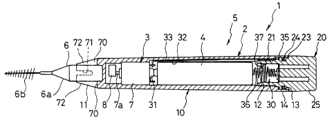
Fig. 1 is a vertical sectional view of an electric
interdental cleaning brush;
Fig. 2 is a vertical sectional detail view of the
electric interdental cleaning brush;
Fig. 3 is a perspective view of a cap member and members
fitted therein;
Fig. 4 is a view corresponding to Fig. 2 showing a
position of a seal ring having just started sealing;
Fig. 5 is a view corresponding to Fig. 2 showing the
state when a supply circuit has been switched ON;
Fig. 6 is a perspective view of the vicinity of a
holding portion of a holder member;
Fig. 7 is a vertical sectional view of a holding portion
and a modified shaft portion;
Fig. 8 is a vertical sectional detail view of modified
male and female thread portions;
Fig. 9 is a view corresponding to Fig. 2 showing part of
an electric interdental cleaning brush according to a first
other preferred embodiment;
Fig. 10 is a vertical sectional detail view of modified
male and female thread portions of the first other preferred
embodiment;
Fig. 11 is a view corresponding to Fig. 1 of an electric
interdental cleaning brush according to a second other
-
21~3~ 2
18
preferred embodiment;
Fig. 12 is a view corresponding to Fig. 2 of part of the
electric interdental cleaning brush according to the second
other preferred embodiment;
Fig. 13 is a sectional view on the line XIII-XIII in
Fig. 12;
Fig. 14 is a view corresponding to Fig. 9 of part of an
electric interdental cleaning brush according to a third
other preferred embodiment;
Fig. 15 is a view corresponding to Fig. 14 of a modified
cap member of the electric interdental cleaning brush
according to the third other preferred embodiment;
Fig. 16 is a perspective view showing a modified cap
side contact piece;
Fig. 17 is a perspective view showing a modified cap
side contact piece;
Fig. 18 is a view corresponding to Fig. 14 of a modified
cap side contact piece;
Fig. 19 is a perspective view of a toothbrush
constituting an oral hygiene tool;
Fig. 20 is a perspective view of a nipple-type gum
massager constituting an oral hygiene tool;
Fig. 21 is a perspective view of a gum massager
constituting an oral hygiene tool;
Fig. 22 is a perspective view of a floss unit
2163~S2
constituting an oral hygiene tool;
Fig. 23 is a view illustrating a vibration mode of an
interdental cleaning brush;
Fig. 24 is a view in the direction of the arrow A in
Fig. 23;
Fig. 25 is a view illustrating a vibration mode of an
interdental cleaning brush in a bent state;
Fig. 26 is a view in the direction of the arrow B in
Fig. 25;
Fig. 27 is a view illustrating a relationship between
holding position and vibration frequency; and
Fig. 28 is a vertical sectional detail view of an
example of a conventional electric interdental cleaning
brush.
Best Modes for Carryinq Out the Invention
Preferred embodiments of the invention will now be
described with reference to the accompanying drawings.
In these preferred embodiments the invention is applied
to a portable electric interdental cleaning brush.
Referring to Fig. 1, a portable electric interdental
cleaning brush 1 comprises a device proper 5 made up of
vibration generating means 3 and a battery 4 housed in a
watertight battery holder 2 and an interdental cleaning brush
6 constituting an oral hygiene tool removably fitted to the
2163~2
left hand end portion of the device proper 5. Other oral
hygiene tools which will be further discussed later such as
a tooth brush 90, a nipple-type gum massaging tool 91, a gum
massaging tool 92 or a floss unit 93 can be fitted to the
device proper 5.
The waterproof battery holder 2 comprises a
substantially cylindrical holder member 10 housing the
vibration generating means 3 and the battery 4, a cap member
20 removably fitted to the holder member 10 and wiring means
constituting a circuit supplying electricity to the
vibration generating means 3. The holder member 10 and the
cap member 20 are made of an insulating synthetic resin
material.
As shown in Fig. 1 and Fig. 2, the holder member 10 is
a cylindrical member closed near its left hand end; a holding
portion 11 for removably holding the interdental cleaning
brush 6 is formed at the left hand end of the holder member
10; a female thread portion 12 is formed on the inner wall of
a portion of the holder member 10 near the right hand end
thereof, and a seal portion 14 having a seal surface 13 of
larger diameter than the female thread portion 12 is formed
on the inside of the right hand end portion of the holder
member 10.
As shown in Fig. 1 to Fig. 3, the cap member 20 is a
substantially cylindrical member whose right hand end is
21637~2
21
closed; a male thread portion 21 which screws into the female
thread portion 12 is formed on a left portion of the cap
member 20; this male thread portion 21 is divided into two
halves by a pair of slits 22 extending in the left-right
direction; a fitting portion 23 of greater diameter than the
male thread portion 21 is formed to the right side of the
male thread portion 21 (the external side of the end of the
meshing of the female thread portion 12 and the male thread
portion 21); a seal ring 24 compressed to form a watertight
seal by the seal surface 13 is fitted in the fitting portion
23, and a grip portion 25 of greater diameter than the
fitting portion 23 for the user to grip when turning the cap
member 20 is formed on the right hand end of the cap member
20.
As shown in Fig. 1, the vibration generating means 3
comprises an electric motor 7 mounted in the left hand end
vicinity of the holder member 10 and an eccentric weight 8
fixed to a rotary shaft 7a projecting to the left from the
electric motor 7, and vibrates the interdental cleaning brush
6 by causing a centrifugal force exerted by the eccentric
weight 8 to act on the holder member 10.
Describing now the wiring means 30, as shown in Fig. 1
to Fig. 3 a cuplike contact piece 31 which makes contact with
the positive pole of the battery 4 is mounted on the right
hand end of the electric motor 7 covering the rotary shaft 7a
21637~2
22
and is connected to one of the terminals of the electric
motor 7; a groove portion 32 extending in the left-right
direction is formed in the inner wall of the holder member
10, a bandlike holder side contact piece 33 connected to the
other terminal of the electric motor 7 is mounted in the
groove portion 32, and the right hand end of the holder side
contact piece 33 extends into the seal portion 14 and engages
with an annular step 34 between the seal portion 14 and the
female thread portion 12.
A substantially disclike cap side contact piece 35 is
fixed to the cap member 20 at the base of the male thread
portion 21, and an outer circumferential portion of the cap
side contact piece 35 faces the right hand end portion of the
holder side contact piece 33; a spring terminal 36 consisting
of a coil spring of enlarged diameter around its central
portion is received in the male thread portion 21; a portion
of the spring terminal 36 part-way therealong is restrained
by a restraining piece 37 fixed in the vicinity of the left
hand end of the male thread portion 21; the right hand end of
the spring terminal 36 is electrically connected to the cap
side contact piece 35, and the left hand end of the spring
terminal 36 passes through a through hole 37a formed in the
restraining piece 37 and makes pressure contact with the
negative pole of the battery 4.
The holder side contact piece 33 and the cap side
~163~52
23
contact piece 35 constitute the contacts of a switch of the
supply circuit; as shown in Fig. 4, the distance l,1 between
the left end surface of the cap side contact piece 35 and the
center of the seal ring 24 is by design shorter than the
distance L2 between the right end surface of the holder side
contact piece 33 and the right end surface of the seal
portion 14; when the cap member 20 is screwed into the holder
member 10 and the periphery of the seal ring 24 in the seal
portion 14 is first pressed upon by the seal surface 13, the
holder side contact piece 33 and the cap side contact piece
35 are a clearance L3 apart; as shown in Fig. 5, when the cap
member 20 is screwed further into the holder member 10 the
cap side contact piece 35 is pressed against the holder side
contact piece 33 and the supply circuit is closed and the
electric motor 7 is driven.
It has been found in monitor tests that here the
required operation angle through which the cap member 20 must
be turned to bring the cap side contact piece 35 and the
holder side contact piece 33 into and out of contact, i.e.
the operation angle required to turn the supply circuit ON or
OFF, is 90 to 150, and the clearance L3 is set to above the
pitch of the thread portions multiplied by 150/360 and
preferably above the value of when the operation angle is set
to above 360 to 450. That is, by setting L3 as large as
possible within the range over which L3+L1 does not exceed
2163~ ~ ~
24
L2, the range of the sealing effect can be widened.
As shown in Fig. 1 and Fig. 6, the holding portion 11 is
a bottomed cylindrical member so formed integra]ly with the
holder member 10 that it closes off the left hand end of the
holder member 10 and is conelike, contracting with progress
toward the left; a pair of first slits 70 and a pair of
second slits 71 are formed alternately in the left portion of
the holding portion 11, uniformly circumferentially spaced
therearound; the first slits 70 are formed from the left hand
end of the holding portion 11 to the vicinity of the inner
back surface, and the second slits 71 are formed from the
left hand end of the holding portion 11 to part-way down the
holding portion 11; four claws 72 are formed by the slits 70
and 71 in the left portion of the holding portion 11. A
different number of slits from that described above may be
provided.
As shown in Fig. 1, the interdental cleaning brush 6
comprises a shaft portion 6a made of synthetic resin or
synthetic rubber or metal or the like which is removably
attached to the holding portion 11 and a brush portion 6b for
interdental cleaning extending to the left from the shaft
portion 6a; the brush portion 6b consists of synthetic resin
filaments embedded in a steel wire, and the brush portion 6b
is fixed to the shaft portion 6a by the right hand end of
this steel wire being embedded in the left hand end of the
2163752
shaft portion 6a.
Because the wall thickness of the holding portion 11
increases with progress toward the inner back surface of the
holding portion 11, and also because the second slits 71 only
extend to part-way along the holding portion 11, strength of
the base portions of the four claws 72 is amply secured.
Because the first slits 70 and the second slits 71 are
provided, the left hand ends of the claws 72 can radially
expand and contract elastically relatively greatly. As a
result, even if there is relatively large variation in the
molding accuracy of the shaft portion 6a, the ho]ding portion
11 can hold the shaft portion 6a firmly and effectively
prevent the interdental cleaning brush 6 from falling out.
Also, because the first slits 70 extend as far as the inner
back surface vicinity of the holding portion ]1, toothpaste
powder and the like clogging the inner back portion of the
holding portion 11 can be easily cleaned off.
Here, as shown in Fig. 7, a discontinuous annular
engaging projection 73 may be provided around the inner
surface of the left end vicinity portion of the claws 72, and
an annular groove 6c for engaging with the engaging
projection 73 may be formed part-way along the shaft portion
6a. In this case, engagement of the engaging projection 73
and the annular groove 6c effectively prevents the
interdental cleaning brush 6 held in the holding portion 11
21637~i2
26
from falling out, and falling out of the interdental cleaning
brush 6 is prevented even when the shaft portion 6a is made
of a hard synthetic resin or metal. When the shaft portion
6a is made of an elasto~er or rubber material, the annular
groove 6c can be dispensed with and falling out of the
interdental cleaning brush 6 effectively prevented by the
engaging projection 73 being allowed to bite into the shaft
portion 6a.
As shown in Fig. 7, tongue portions 6d which can engage
with the first slits 70 or the second slits 71 can be
provided on the base end portion of the shaft portion 6a. In
this case, the interdental cleaning brush 6 can be fitted to
the portable interdental brush 1 in such a state that it
cannot rotate and the operability of the interdental cleaning
brush 6 increases. Protrusions may be provided instead of
the tongue portions 6d.
Next, the operation of the electric interdental cleaning
brush l will be described.
When the cap member 20 is screwed into the holder member
10, first, as shown in Fig. 4, the seal ring 24 is pressed
upon by the seal surface 13 and the interior of the holder
member 10 is thereby watertightly sealed; when the cap member
20 is further screwed in through a predetermined angle, as
shown in Fig. 5, with the interior of the holder member 10
thus watertightly sealed, the cap side contact piece 3S is
21~37~2
pressed against the holder side contact piece 33, the supply
circuit is closed, the electric motor 7 is driven and the
interdental cleaning brush 6 is vibrated.
When the cap member 20 is turned through 90 to 150 in
the opposite direction, as shown in Fig. 2, the cap side
contact piece 35 moves away from the holder side contact
piece 33 and the electric motor 7 stops. At this time, the
seal ring 24 is kept pressed against the seal surface 13 and
the interior of the holder member 10 is kept watertight.
Furthermore, in this state, rotation of the cap member 20 is
restricted by the seal ring 24 being pressed upon by the seal
surface 13, and accidental operation of the electr;c motor 7
and detachment of the cap member 20 are prevented. From the
next time, the supply circuit is switched ON and OFF by the
cap member 20 being turned between the state shown in Fig. 5
and the state shown in Fig. 2.
Because thus over the range of turning of the cap member
20 which switches power to the electric motor 7 ~N and OFF
the gap between the cap member 20 and the holder member 10 is
sealed by the seal ring 24, the interior of the holder member
10 can be kept watertight at all times. Furthermore, when
the electric interdental cleaning brush 1 is being used, even
when the cap member 20 has become loose and the gap between
the cap member 20 and the holder member 10 is not being
sealed properly by the seal ring 24, to operate the electric
21637~2
28
motor 7 it is necessary to turn the cap member 20 as shown in
Fig. 5, and because the gap between the cap member 20 and the
holder member 10 becomes sealed as a result of this turning
of the cap member 20 the incursion of water or the like into
the interior of the holder member 10 while the electric
interdental cleaning brush 1 is being used can be prevented
with certainty. Also, even when the electric interdental
cleaning brush 1 is for example washed with the cap member 20
loose, as long as the cap member 20 is not so loose that the
sealing effect of the seal ring 24 is lost, incursion of
water or the like is prevented with certainty.
Also, because power to the electric motor 7 can be
switched ON and OFF by bringing the cap side contact piece 35
into and out of contact with the holder side contact piece
33, the switch structure of the supply circuit can be
simplified and the sealing structure thereof can be
simplified, and the constitution of the device proper 5 can
be greatly simplified.
Furthermore, the incursion of toothbrushing water and
the like to between the meshing portions of the female thread
portion 12 and the male thread portion 21 is prevented by the
seal ring 24, and problems such as toothbrushing water
hardening on the meshing portions of the thread portions 12
and 21 and making it difficult to turn the cap member 20 are
prevented.
2163~2
29
To reduce the frictional resistance between the cap
member 20 and the holder member 10, the seal ring 24 may be
made somewhat soft (hardness about 50) and its surface may be
coated with a friction reducer such as teflon.
As shown in Fig. 8, a play G can be provided between the
male thread portion 21 and the female thread portion 12 and
the cap member 20 brought to a state wherein it is screwed in
to a position such that the circuit supplying current to the
electric motor 7 is just about to be closed; then by pushing
the cap member 20 the cap side contact piece 35 can be moved
through the play G between the male thread portion 21 and the
female thread portion 12 and brought into contact with the
holder side contact piece 33, thereby closing the supply
circuit, and by ceasing pushing the cap member 20 the cap
member 20 can be allowed to return to its original position
under the spring force of the spring terminal 36 so that the
cap side contact piece 35 moves away from the holder side
contact piece 33 and the supply circuit is opened.
Next, a first other preferred embodiment consisting of
the electric interdental cleaning brush 1 with partial
modifications made thereto will be described. Parts of this
preferred embodiment which are the same as parts in the
preferred embodiment described above have been given the same
reference numerals and a detailed description thereof will be
omitted.
2163~2
This electric interdental cleaning brush 40, as shown in
Fig. 9, basically is so constituted that a female thread
portion 61 formed in a cap member 60 is screwed into a male
thread portion 51 formed on a holder member 50 and the cap
member 60 is thereby fitted to the holder member 50.
The male thread portion 51 is formed on the right hand
end portion of the holder member S0, a seal ring 52 is fitted
in the vicinity of the base end of the male thread portion
51, and the right hand end portion of a holder side contact
piece 53 is hooked around the right hand end portion of the
female thread portion 51.
The cap member 60 is a bottomed cylindrical member; the
male thread portion 61 which screws into the female thread
portion 51 is formed on the inner wall of the left hand end
vicinity of the cap member 60; a seal portion 63 having a
seal surface 62 of greater internal diameter than the male
thread portion 61 is formed on the left hand end portion of
the cap member 60; a disclike cap side contact piece 64 is
fixed to an inner back portion of the cap member 60 facing
the holder side contact piece 53, and a spring terminal 65
consisting of a coil spring narrowing toward the left is
fixed to the cap side contact piece 64.
In the electric interdental cleaning brush 40, the
distance Ll between the center of the seal ring 52 and the
right hand end of the holder side contact piece 53 is by
2 1 6 3 ~ 5 2
design shorter than the distance L2 between the left hand end
of the seal portion 63 and the left hand end surface of the
cap side contact piece 64, and when the cap member 60 is
screwed onto the holder member 50 and the seal ring 52 is
first pressed upon by the left hand end of the seal portion
63, a clearance is formed between the holder s;de contact
piece 53 and the cap side contact piece 64.
As in the preferred embodiment described earlier, in the
electric interdental cleaning brush 40 also the electric
motor 7 can be switched ON and OFF with the gap between the
cap member 60 and the holder member 50 sealed by the seal
ring 52, and there are the same actions and effects of the
earlier preferred embodiment such as that water and the like
can be effectively prevented from getting inside the holder
member 50 while the electric interdental cleaning brush 40 is
being used.
As shown in Fig. 10, a play G can be provided between
the male thread portion 51 and the female thread portion 61
and the cap member 60 brought to a state wherein it is
screwed in to a position such that the circuit supplying
current to the electric motor 7 is just about to be closed;
then by pushing the cap member 60 the cap side contact piece
64 can be moved through the play G between the male thread
portion 51 and the female thread portion 61 and brought into
contact with the holder side contact piece 53, thereby
216375~
closing the supply circuit, and by ceasing push;ng the cap
member 60 the cap member 60 can be allowed to return to its
original position under the spring force of the spring
terminal 65 so that the cap side contact piece 64 moves away
from the holder side contact piece 53 and the supply circuit
is opened.
The operation of turning the cap member 20 or 60 may be
given a sense of definiteness by forming long circumferential
grooves in the holder member 10 or 50 or the cap member 20 or
60 and forming engaging projections on the cap member 20 or
60 or the holder member 10 or 50 which engage with the long
grooves, restricting the range of turn of the cap member 20
or 60 by means of the engaging projections and the long
grooves and thereby preventing the cap member 20 or 60 from
being turned beyond the range of turn for switching the
electric motor 7 ON and OFF.
In these preferred embodiments, the supply circuit is
switched ON and OFF by the cap member 20 or 60 being turned;
however, a separate switch may be provided in the supply
circuit and the supply circuit may be switched ON and OFF by
operation of this switch.
Next, a second other preferred embodiment consisting of
the electric interdental cleaning brush 1 with partial
modifications made thereto will be described. Parts of this
preferred embodiment which are the same as parts in the
~l6~s2
preferred embodiments described above have been given the
same reference numerals and a detailed description thereof
will be omitted.
This electric interdental cleaning brush 80 consists of
the electric interdental cleaning brush 1 with the
constitution of the wiring means 30 modified; as shown in
Fig. 11 through Fig. 13, in the wiring means 30A used in this
electric interdental cleaning brush 80, a spring terminal 81
contactable with the positive pole of the battery 4 is
mounted on a substantially central portion of the right hand
end of the electric motor 7; the base end portion of the
spring terminal 81 is connected to one terminal of the
electric motor 7, and the other contact of the electric motor
7 is connected to a bandlike holder side contact piece 33 as
in the preferred embodiments described above.
A cap member 20A like the above-mentioned cap member 20
but without the slits 22 has formed on its inner back surface
a pillarlike mounting portion 82 projecting to the left
beyond the left hand end of the rest of the cap member 20A,
and a cap side contact piece 83 is mounted on the end of the
mounting portion 82.
The cap side contact piece 83 has an opening 83a through
which the mounting portion 82 passes, and is fi.tted over the
end portion of the mounting portion 82; the cap side contact
piece 83 is integrally made up of an annular brim portion 83b
2163752
extending from the vicinity of the mounting portion 82 to the
left hand end portion of the cap member 20A and a bandlike
contact portion 83c provided straddling the front side of the
end of the mounting portion 82 and formed by so pressing the
portion of the brim portion 83b corresponding to the opening
83a that it projects to the left; portions of the mounting
portion 82 exposed at the sides of the contact portion 83c
are melted to form a flat portion 82a, and the cap side
contact piece 83 is held on the end of the mounting portion
82 by the flat portion 82a engaging with the brim portion
83b.
In the wiring means 30A, the right hand end of the
spring terminal 81 makes contact with the positive pole of
the battery 4, the battery 4 is urged to the right by the
urging force of the spring terminal 81, and the negative pole
of the battery 4 makes contact with the left end of the
contact portion 83c. When the cap member 20A is screwed into
the holder member 10 until it is inside the above-mentioned
predetermined angle range, the right end of the holder side
contact piece 33 makes contact with the outer circumferential
edge portion of the left end surface of the brim portion 83b
and current is supplied to the electric motor 7.
Thus, in the electric interdental cleaning brush 80, it
is possible to fix the base end of the spring terminal 81 to
one terminal of the electric motor 7 by hang-fixing or
21fi3~i52
otherwise and the cap side contact piece 83 also can be
easily mounted by forming the flat portion 82a by melting the
portions of the mounting portion 82 which are exposed on
either side of the contact portion 83c. Furthermore, the
number of parts can be reduced, and because the constitution
of the cap member 20A becomes simple the constitution of
molds used to mold the cap member 20A can be greatly
simplified.
The wiring means of the electric interdental cleaning
brush 40 of the first other preferred embodiment may be
constituted in the same way as in the second other preferred
embodiment. That is, as shown in Fig. 14, a spring terminal
81 may be connected to one terminal of the electric motor 7,
a pillarlike mounting portion 82 projecting to the left
formed on the inner back surface of a cap member 60A, and a
cap side contact piece 83 fitted to the left end of this
mounting portion 82. As shown in Fig. 15, a cap member 60B
like the cap member 60A but without the right hand half may
be provided, a mounting portion 82 formed on the inner back
surface of this cap member 60B, and a cap side contact piece
83 fixed with a brim portion 83b in contact with the inner
back surface of the cap member 60B.
As shown in Fig. 16, engaging projections 84 may be
formed projecting inward around the opening 83a of the brim
portion 83b of the cap side contact piece 83, and when
216375~
36
fitting the brim portion 83b to the mounting portion 82 the
engaging projections 84 can be caused to engage with the
circumferential surface of the mounting portion 82 and the
cap side contact piece 83 thereby fixed to the cap member
20A, 60A or 60B. Also, as shown in Fig. 17, the contact
portion 83c may be of cantilever form. Also, as shown in
Fig. 18, the cap side contact piece 83 may be made hat-shaped
with a brim, an annular projecting portion 83e may be
provided projecting inward from a portion of the mounting
portion 82 near the end thereof, an annular groove 82b which
engages with the projecting portion 83e may be provided in
the vicinity of the end of the mounting portion 82, and the
cap side contact piece 83 may be fixed to the mounting
portion 82 by the projecting portion 83e being caused to
engage with the annular groove 82b. Instead of the flat
portion 82a, without melting the portions of the mounting
portion 82 exposed on either side of the contact portion 83c,
the contact portion 83c may be fixed to the mounting portion
82 with an adhesive such as a hot melt.
Next, oral hygiene tools which can be removably attached
to the holding portion 11 other than the interdental cleaning
brush 6 will be described.
As one such oral hygiene tool, as shown in Fig. 19, a
toothbrush 90 consisting of a bristle bed formed on the end
of a shaft portion 6a and a plurality of b~istles 90b
2163~52
embedded in this bristle bed 9Oa may be used.
As another such oral hygiene tool, as shown in Fig. 20,
a nipple-type gum massager 91 consisting of a circular head
portion 91a formed on the end of a shaft portion 6a and a
tapered rubber member 9lb mounted on this head portion 9la
may be used.
As another such oral hygiene tool, as shown in Fig. 21,
a gum massager 92 consisting of a baglike rubber member 92a
mounted on the end of a shaft portion 6a and a plurality of
protrusions 92b formed on the upper surface of this rubber
member 92a may be used.
As still another oral hygiene tool, as shown in Fig. 22,
a floss unit 93 consisting of a pair of arm portions 93a
formed on the end of a shaft portion 6a and a length of
dental floss 93b strung between the ends of the arm portions
93a may be used.
Next, the vibration state of the interdental cleaning
brush 6 induced by the vibration generating means 3 will be
described.
This vibration generating means 3 generates vibration by
rotating the eccentric weight 8; as shown in Fig. 23, when
the steel wire portion of the brush portion 6b is disposed
coaxially with the center axis of the shaft portion 6a, as
shown in Fig. 24 the end of the brush portion 6b rotates
clockwise or counterclockwise in a circle of diameter
'~16~7~2
(amplitude) Rl. When the brush portion 6b and the shaft
portion 6a are thus disposed coaxially, when the brush
portion 6b is inserted between teeth and vibrated, mainly the
interdental surrounding areas are cleaned. When with the
brush portion 6b vibrating it is moved back and forth in the
axial direction, the cleaning effect can be greatly
increased.
As shown in Fig. 25, when the steel wire Or the brush
portion 6b is bent at its base portion through ~0, as shown
in Fig. 26 the end of the brush portion 6b rotates clockwise
or counterclockwise in a circle of diameter (amplitude) R2.
When the brush portion 6b is bent like this, the brush
portion 6b moves back and forth between the teeth and mainly
cleans between the teeth.
In the vibration generating means 3, because vibration
acts on the interdental cleaning brush 6 through the holder
member 10, it is possible to adjust the amplitudes Rl, R2 and
the speed (the vibration frequency) of the end o~ the brush
portion 6b by way of what part of the holder member 10 is
held.
In other words, as shown in Fig. 27, because the
confining action of the user's hand on the vibration of the
tool becomes greater and the amplitude and frequency become
smaller the nearer toward the tool end the holder member 10
is held, by holding the holder member 10 near its rear end
21 63~ 2
when strong brushing is desired and holding the ho]der member
10 near its front end when gentle brushing is desired, it is
possible to adjust the brushing strength.
Industrial Applicability
In an oral hygiene instrument according to claim 1, by
means of a simple construction wherein until the gap between
the holder member and the cap member is sealed with certainty
by the seal ring the holder side contact piece and the cap
side contact piece are kept apart and the supply circuit is
open, supplying of power to the vibration generating means
when the cap member has become loose is prevented and the
user is made known of the lack of sealing and the incursion
of water and the like into the holder member is completely
prevented. Also, the incursion of toothbrushing water and
the like into where the holder side thread portion and the
cap side thread portion mesh can be prevented with certainty,
and problems caused by toothbrushing water hardening between
the two meshing thread portions and making it difficult to
turn the cap member can be prevented.
In an oral hygiene instrument according to claim 2,
because switch contacts are constituted by the holder side
contact piece and the cap side contact piece it is not
necessary to separately provide a switch for opening and
closing the supply circuit and furthermore it is possible to
2163~52
open and close the supply circuit with the gap between the
holder member and the cap member sealed with certainty and
the switch structure and the sealing structure thereof can be
simplified and the constitution of the oral hygiene
instrument can be greatly simplified. Also, when the supply
circuit is closed, even if the instrument is washed with
water, because watertightness is maintained, breakdowns and
hardening making opening and closing of the thread portions
difficult caused by the incursion of water do not occur.
Furthermore, with the supply circuit open, even when the
instrument is left between uses, frictional action of the
sealing ring prevents the threads from loosening or
tightening on their own.
In an oral hygiene instrument according to claim 3,
because if the gap between the holder member and the cap
member is not sealed properly it is impossible to close the
supply circuit by operating the switch, the lack of sealing
is made known to the user and the incursion of water and the
like into the holder member is completely prevented.
In an oral hygiene instrument according to claim 4, by
means of a simple constitution wherein an axial play is
provided between the holder side thread portion and the cap
side thread portion it is possible to close the supply
circuit by pushing the cap member, and by having the holder
side contact piece and the cap side contact p;ece double as
2163~52
41
the contacts of a push switch the switch structure and the
sealing structure thereof can be simplified and the
constitution of the oral hygiene instrument can be greatly
simplified.
In an oral hygiene instrument according to claim 5,
because the plurality of first and second slits are provided
in the holding portion, the end of the holding portion can
elastically expand and contract radially relatively greatly,
and even if there are relatively large variations in the
molding accuracy of the shaft portion the shaft portion can
be held with certainty and the oral hygiene tool prevented
from falling off, and because the first slits extend to the
vicinity of the inner back surface of the holding portion,
cleaning off of toothpaste powder and the like clogging the
inner back portion of the holding portion is easy. Also,
because the shaft portion of the oral hygiene tool can be of
a simple bar shape, manufacturing of the oral hygiene
instrument can be simplified.
In an oral hygiene instrument according to claim 6, by
providing a simple engaging projection on the inner
circumferential side of the holding portion in the vicinity
of the end thereof, axial movement of the oral hygiene tool
is restricted and it is more effectively prevented from
coming off.
In an oral hygiene instrument according to claim 7, by
2163752
42
providing simple tongue projections or protrusions on the
outer circumferential surface of the oral hygiene tool,
rotation of the oral hygiene tool about the shaft portion is
restricted and the operability of the oral hygiene instrument
is greatly increased.
In an oral hygiene instrument according to claim 8,
because a spring terminal is fitted to the vibration
generating means and a cap side contact piece comprising a
brim portion and a contact portion is fitted to the cap
member, the constitution of the cap member can be greatly
simplified and compared to a case wherein a spring terminal
is fixed to the cap member the work of installing the spring
terminal can be greatly simplified.
In an oral hygiene instrument according to claim 9, the
cap side contact piece can easily be fitted to the cap member
by the cap side contact piece being press-fitted onto the
mounting portion and the engaging projection being caused to
engage with the outer circumferential surface of the mounting
portion.
In an oral hygiene instrument according to claim 10,
because with the cap side contact piece fitted to the
mounting portion a flat portion is formed by melting the
portions of the mounting portion exposed on either side of
the contact portion, it is possible to easily fix the cap
side contact piece to the cap member by preventing the cap
7 ~ 2
43
side contact piece from falling by means of the flat portion.
In an oral hygiene instrument according to claim 11, as
in claim 1, because until the gap between the holder member
and the cap member is sealed with certainty by the seal ring
the supply circuit cannot be closed and the vibration
generating means cannot be driven, as a result it is made
known to the user that sealing is not being effected properly
and the incursion of toothbrushing water or the like into
where the holder member and the cap member mesh is prevented
with certainty by the seal ring. Also, as in the instrument
of claim 5, because a plurality of first slits and second
slits are provided in the holding portion, the end of the
holding portion can elastically expand and contract radially
relatively greatly, and even if there are relatively large
variations in the molding accuracy of the shaft portion the
shaft portion can be held with certainty and the or~l hygiene
tool prevented from falling off, and because the first slits
extend to the vicinity of the inner back surface of the
holding portion, cleaning off of toothpaste powder and the
like clogging the inner back portion of the holding portion
is easy. Also, as in the instrument of claim 8, because the
spring terminal is fitted to the vibration generating means
and the cap side contact piece comprising the brim portion
and the contact portion is fitted to the cap member, the
constitution of the cap member can be greatly simplified and
2163~5~
44
compared to a case wherein a spring terminal is fixed to the
cap member the work of installing the spring terminal can be
greatly simplified.