Language selection

Search

Patent 2164192 Summary

Third-party information liability

Some of the information on this Web page has been provided by external sources. The Government of Canada is not responsible for the accuracy, reliability or currency of the information supplied by external sources. Users wishing to rely upon this information should consult directly with the source of the information. Content provided by external sources is not subject to official languages, privacy and accessibility requirements.

Claims and Abstract availability

Any discrepancies in the text and image of the Claims and Abstract are due to differing posting times. Text of the Claims and Abstract are posted:

  • At the time the application is open to public inspection;
  • At the time of issue of the patent (grant).
(12) Patent Application: (11) CA 2164192
(54) English Title: EQUIPMENT FOR TRANSFER OF BULK MATERIAL
(54) French Title: EQUIPEMENT SERVANT A TRANSFERER DES MATERIAUX EN VRAC
Status: Deemed Abandoned and Beyond the Period of Reinstatement - Pending Response to Notice of Disregarded Communication
Bibliographic Data
(51) International Patent Classification (IPC):
  • B65G 65/28 (2006.01)
  • B65G 65/06 (2006.01)
(72) Inventors :
  • MUSTAKOSKI, JORMA (Finland)
(73) Owners :
  • JORMA MUSTAKOSKI
(71) Applicants :
(74) Agent: MCCARTHY TETRAULT LLP
(74) Associate agent:
(45) Issued:
(86) PCT Filing Date: 1994-05-25
(87) Open to Public Inspection: 1994-12-08
Examination requested: 2001-03-23
Availability of licence: N/A
Dedicated to the Public: N/A
(25) Language of filing: English

Patent Cooperation Treaty (PCT): Yes
(86) PCT Filing Number: PCT/FI1994/000209
(87) International Publication Number: WO 1994027898
(85) National Entry: 1995-11-30

(30) Application Priority Data:
Application No. Country/Territory Date
932503 (Finland) 1993-06-01

Abstracts

English Abstract


The invention relates to an appara-
tus for transferring loose material such as
peat, wood chips, coal and the like to fur-
ther processing. The said equipment is
comprised of a conveyor (1), a suspend-
ing element (2) for the conveyor, an el-
ement monitoring the suspension load (4),
and advantageously an element monitoring
the vertical deflection of the suspending el-
ement in the direction of the horizontal dis-
placement of the conveyor. The element
monitoring the suspension load (4) con-
trols the raising and lowering device (3)
connected to the suspending element (2)
in order to maintain the suspension load
of the conveyor (1) at a set value advanta-
geous for the efficiency of discharging.


French Abstract

L'invention concerne un appareil permettant le transfert de matières en vrac telles que de la tourbe, des copeaux de bois, du charbon et l'équivalent destinés à subir un traitement supplémentaire. Ledit équipement est doté d'un convoyeur (1), d'un élément suspendu (2) pour le convoyeur (1), d'un élément de contrôle de la charge suspendue (4) et d'un élément de contrôle de la déflexion verticale de l'élément suspendu dans le sens de déplacement horizontal du convoyeur. L'élément contrôlant la charge de suspension (4) commande le dispositif de levage et d'abaissement (3) relié à l'élément suspendu (2) de manière à maintenir la charge de suspension du convoyeur (1) à une valeur prédéterminée avantageuse pour l'efficacité du déchargement.

Claims

Note: Claims are shown in the official language in which they were submitted.

Claims:
1. An apparatus for transferring heaped loose material
such as peat, wood chips, coal and the like, the said
apparatus comprising a conveyor (1) acting upon the sur-
face of a heap of loose material, the conveyor being
hinged vertically turnable at least at one end, and sus-
pended at the opposite end by a suspending element (2) on
a raising and lowering device (3) so that it can be rais-
ed and lowered in a controlled manner, the conveyor fur-
ther being essentially horizontally displaceable at least
from its suspended end, characterised in that in order to
regulate the transfer load of the conveyor (1), the ap-
paratus contains an element (4) in connection with the
suspension device (2), the element (4) controlling the
raising and lowering device (3) by monitoring the suspen-
sion load to stay at a preset value.
2. An apparatus as claimed in claim 1, characterised in
that it further includes elements (5) for monitoring the
vertical deflection of the suspending element (2) in the
horizontal displacement direction of the conveyor (1).
3. An apparatus as claimed in claim 2, characterised in
that it includes processing means for providing control
commands for the raising and lowering device (3) and/or
the lateral displacement device on the basis of informa-
tion supplied by the element controlling the suspension
load (4) and the element monitoring the vertical deflec-
tion (5).

Description

Note: Descriptions are shown in the official language in which they were submitted.


~94/27898 ` PCT/~94/00209
F,quip~ent f~r transfer ~r bulk materlal.
The object of the invention is an apparatus for transfer-
ring loose material such as peat, wood chips, coal, sand
and the like from heaps or the like for further process-
ing. In order to be able to perform the transfer, the
apparatus is comprised of a conveyor, which preferably is
a drag conveyor influencing the surface of the heap, such
as a drag bar conveyor, for instance. Such a conveyor is
designed to be raised and lowered vertically so that the
conveyor is hinged at its discharge end in order to be
turnable at least vertically. At the opposite end, the
conveyor is suspended on a suitable raising and lowering
device.
In order to extend the conveyor's area of operation, it
is designed to be horizontally transferrable at least in
respect to its end suspended on the raising and lowering
device, whereby a sector equal to the horizontal dis-
placement can be managed by the conveyor. Alternatively,the discharge end of the conveyor may be constructed to
promote also a horizontal displacement in order to ex-
tend the area managed by the conveyor. From the point of
view of operation, it is advantageous also to have the
discharge end of the conveyor vertically displaceable in
order to be able to cope with different initial situ-
ations considering the size and shape of the material
heap.
Apparatuses of this kind are as such prior known and when
using them the flow of material removed from the heap can
be adjusted by lowering the conveyor in pace with the
receding of the surface of the heap. The horizontal dis-
placement of the conveyor is executed appropriately by
having the heap removed essentially one horizontal slice
at a time. The use of prior known control devices in
these apparatuses leads to abundant idle operation, when
the conveyor hangs on its lowering device too high with

W094/27898 ~ 2 PCT/~94/00209
respect to the surface of the heap. On the other hand the
control device may lower the conveyor too rapidly with
respect to the conveyor's discharge capacity and thereby
cause overloading of the conveyor.
The apparatus according to the invention provides im-
provements in regard to the shortcomings of prior known
apparatuses so that the apparatus comprises a device
which is connected to the suspension device, and controls
the raising and lowering device by monitoring the suspen-
sion load.
In accordance with a further characteristic of the inven-
tion, it is possible to eliminate the groping associated
with prior known apparatuses when being laterally dis-
placed. In such situations, the prior known conveyors
collide with the side of the heap too far up and operate
at less than full capacity or if embedded too far into
the heap they operate overloaded. This problem is elimin-
ated by providing the apparatus with elements for moni-
toring the vertical displacement of the suspending
element while the conveyor is being laterally displaced.
Another advantage of this further characteristic is that
it accounts for changes caused on the heap from outside.
An example of such a change is a supplementary load of
material being added to the heap.
The invention is described in more detail by means of an
equipment shown in the appended figures as one embodiment
of the invention. In the drawings:
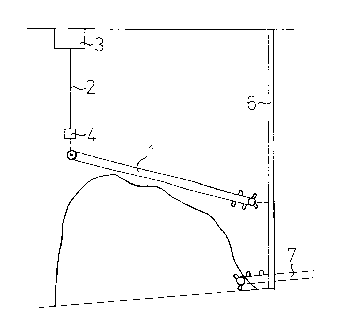
Figure 1 shows a side view of one recommended realis-
ation of the apparatus in accordance with the inven-
tion,5
Figure 2 shows a part of apparatus seen from the sus-
pended end of the conveyor and

h~
~94/27898 PCT/F~4/00209
Figure 3 shows a view from above of the apparatus
shown in Figure 1.
Figure 1 is a schematic presentation of the basic realis-
ation of the apparatus for the purpose of removing loose
fuel material from a heap of the said material. The basic
parts of the apparatus are the conveyor 1, attached from
its discharge end to a pillar 6. This attachment is ex-
ecuted in a hinged manner so that the conveyor 1 can beswung both vertically and horizontally. The conveyor 1 is
attached to a raising and lowering device 3 by means of a
suspending element 2 at the end opposite to its discharge
end. The discharge end of the conveyor 1 shows a dis-
charge conveyor 7 onto which the conveyor 1 surrendersthe material removed from the heap of material. The said
discharge conveyor can, for instance, convey the material
to a combustion plant.
The raising and lowering device 3 is used to lower the
pick-up end of the conveyor in pace with the receding of
the surface of the heap as material is removed. A sensor
4 for recognising the suspension load imposed by the con-
veyor 1 on the suspending element 2 is embodied in the
set of equipment in accordance with the invention for the
purpose of controlling the said lowering. The sensor 4
controls the raising and lowering device 3 so that the
suspension load sensed by the sensor stays at the set
value. The said control ensures that the conveyor 1 is
lowered to conform with the surface of the heap so that
the conveyor's transfer function is maximised, whereupon
idle operation and overload situations are avoided.
As another control sensor, the apparatus includes a sen-
sor 5 (Fig. 2) for monitoring the vertical displacement
of the suspending element 2 which controls the func-
tioning of the lateral displacement carriage of the

W094/27898 PCT/~94/00209
21~41~ 4
lowering and raising device 3. The purpose of the said
sensor is to inform the control device of the horizontal
displacement of the conveyor, and to prevent the conveyor
from becoming disadvantageously positioned with respect
to the side of the heap of material when the conveyor is
displaced horizontally. In the event that the conveyor
collides with the side of the heap of material at a point
unsuitably low, the said collision will cause the sus-
pending element 2 to be deflected from the vertical plane
and this deflection is recognised by the sensor 5. The
sensor 5 informs the control device of the occurrence
whereupon the control device issues a command to the
raising and lowering device 3 to raise the conveyor by a
certain amount prior to proceeding to continuing with its
horizontal displacement. If the conveyor still collides
with the side of the heap, the aforementioned function is
repeated until the sensor 5 no longer senses deflection
from the vertical of the suspending element as lateral
displacement proceeds. When this is the case, the control
mechanism assumes the conveyor to have reached the top of
the heap of material and commences the transfer function
by lowering the conveyor guided by the information re-
layed by the sensor 4 sensing the suspension load.
In the above situation, the heap of material may be
transferred using the conveyor 1 by allowing the conveyor
to come down a predefined distance after which it is
raised slightly, displaced laterally a predefined step,
lowered to the transfer position, allowed to come down
while executing the transfer function, etc. However, the
set of equipment in accordance with the invention also
makes possible essentially linear proceeding at a speci-
fic elevation thereby sweeping over the entire heap of
material. When this is done, the starting point is the
aforementioned top position and the conveyor sweeps away
a slice of certain thickness per lateral displacement. In
this function model, the sensor 4 sensing the suspension

~G4 1 ~
094/27898 PCT/~94/00209
load of the control element controls mainly the lateral
displacement of the transfer carriage of the raising and
lowering element 3 in such a manner that the load imposed
on the sensor 4 stays at a certain value, monitored by
the vertical deflection sensor 5. In accordance with
these function models, and by way of an example, the ap-
paratus is able to recognise supplementary loads added
onto the heap of material since the preceding sweeping
cycle and to control without any problems the conveyor
also when it reaches point where the supplementary load
was added.
The said basic set of equipment can, for instance, be
operated within a certain sector finally delimited by the
limit switches 8 of the transfer carriage of the raising
and lowering device 3. The control logic for the set of
equipment may also be thus construed that the movements
of the conveyor serve to indicate when the edge of the
heap of material has been reached and thereby avoid un-
necessary lateral displacement of the conveyor.
In Figure 3, the set of equipment shown in Figure 1 ispresented schematically as seen from above. In this ap-
plication, the discharge end of the conveyor 1 is
attached to the pillar 6 and the pick-up end is attached
to the raising and lowering device 3 which in turn moves
along a circular track with the pillar 6 as its centre.
The above basic apparatus can be supplemented by means of
modifications such as those shown in the appended draw-
ings. The hinged point of attachment to pillar 6 of the
discharge end of the conveyor 1 can be achieved so that
it can be moved vertically along the pillar 6. This fa-
cilitates the advantageous positioning of the conveyor 1
in readiness for dealing with material heaps of varying
sizes and shapes.

W094/27898 PCT/~94/00209
~ 9~ 6
Further, the invention facilitates the mounting of the
hinged point of attachment to pillar 6 of the discharge
end of the conveyor 1 can be executed so that it can be
moved laterally in which case the set of equipment can be
operated covering a rectangular area of heaped material
instead of a sector.
In the above, the invention is described as being appro-
priate for the discharging of loose material from heaps,
but the said equipment can also be applied for the oppo-
site purpose, that of forming heaps of loose material.

Representative Drawing
A single figure which represents the drawing illustrating the invention.
Administrative Status

2024-08-01:As part of the Next Generation Patents (NGP) transition, the Canadian Patents Database (CPD) now contains a more detailed Event History, which replicates the Event Log of our new back-office solution.

Please note that "Inactive:" events refers to events no longer in use in our new back-office solution.

For a clearer understanding of the status of the application/patent presented on this page, the site Disclaimer , as well as the definitions for Patent , Event History , Maintenance Fee  and Payment History  should be consulted.

Event History

Description Date
Inactive: IPC from MCD 2006-03-12
Application Not Reinstated by Deadline 2005-09-12
Inactive: Dead - No reply to s.30(2) Rules requisition 2005-09-12
Deemed Abandoned - Failure to Respond to Maintenance Fee Notice 2005-05-25
Inactive: Abandoned - No reply to s.30(2) Rules requisition 2004-09-13
Inactive: S.30(2) Rules - Examiner requisition 2004-03-12
Amendment Received - Voluntary Amendment 2001-06-20
Letter Sent 2001-04-10
Inactive: Status info is complete as of Log entry date 2001-04-10
Inactive: Application prosecuted on TS as of Log entry date 2001-04-10
Request for Examination Requirements Determined Compliant 2001-03-23
All Requirements for Examination Determined Compliant 2001-03-23
Application Published (Open to Public Inspection) 1994-12-08

Abandonment History

Abandonment Date Reason Reinstatement Date
2005-05-25

Maintenance Fee

The last payment was received on 2004-04-13

Note : If the full payment has not been received on or before the date indicated, a further fee may be required which may be one of the following

  • the reinstatement fee;
  • the late payment fee; or
  • additional fee to reverse deemed expiry.

Please refer to the CIPO Patent Fees web page to see all current fee amounts.

Fee History

Fee Type Anniversary Year Due Date Paid Date
MF (application, 4th anniv.) - small 04 1998-05-25 1998-05-08
MF (application, 5th anniv.) - small 05 1999-05-25 1999-05-12
MF (application, 6th anniv.) - small 06 2000-05-25 2000-03-28
Request for examination - small 2001-03-23
MF (application, 7th anniv.) - small 07 2001-05-25 2001-05-01
MF (application, 8th anniv.) - small 08 2002-05-27 2002-03-25
MF (application, 9th anniv.) - small 09 2003-05-26 2003-03-31
MF (application, 10th anniv.) - small 10 2004-05-25 2004-04-13
Owners on Record

Note: Records showing the ownership history in alphabetical order.

Current Owners on Record
JORMA MUSTAKOSKI
Past Owners on Record
None
Past Owners that do not appear in the "Owners on Record" listing will appear in other documentation within the application.
Documents

To view selected files, please enter reCAPTCHA code :


To view images, click a link in the Document Description column. To download the documents, select one or more checkboxes in the first column and then click the "Download Selected in PDF format (Zip Archive)" or the "Download Selected as Single PDF" button.

List of published and non-published patent-specific documents on the CPD .

If you have any difficulty accessing content, you can call the Client Service Centre at 1-866-997-1936 or send them an e-mail at CIPO Client Service Centre.


Document
Description 
Date
(yyyy-mm-dd) 
Number of pages   Size of Image (KB) 
Representative drawing 1998-07-16 1 5
Cover Page 1996-04-24 1 15
Abstract 1994-12-08 1 37
Description 1994-12-08 6 251
Claims 1994-12-08 1 38
Drawings 1994-12-08 3 20
Claims 2001-05-07 1 42
Reminder - Request for Examination 2001-01-29 1 118
Acknowledgement of Request for Examination 2001-04-10 1 178
Courtesy - Abandonment Letter (R30(2)) 2004-11-22 1 167
Courtesy - Abandonment Letter (Maintenance Fee) 2005-07-20 1 175
PCT 1995-11-30 10 393
Fees 2003-03-31 1 32
Fees 2001-05-01 1 36
Fees 2002-03-25 1 35
Fees 1998-05-08 1 40
Fees 1999-05-12 1 35
Fees 2000-03-28 1 37
Fees 2004-04-13 1 25
Fees 1997-04-14 1 37
Fees 1995-11-30 1 45