Note: Descriptions are shown in the official language in which they were submitted.
~~~E~ ~f~f~t'"~ T~'~ ~ ~ ~ ~P~"'u~~
T-'Tt'A~~~~"~''.a ~~'1
Building Element
The invention relates to a building element consisting
of two parallel welded wire grid mats with square or
rectangular meshes, of web wires which hold the wire grid
mats at a predetermined distance apart, extend obliquely to
the wire grid mats, and are joined at each end to the two
wire grid mats, and of a one-piece insulating body which is
arranged between and at predetermined distances from the wire
grid mats and through which the wire grids pass, wherein the
web wires are arranged in parallel rows between the wires of
the wire grid mats.
From AT-PS 372 886 a method and an apparatus for
producing a building element of this kind are known. For
this purpose two lengths of wire grid are first brought into
a parallel position at a distance apart corresponding to the
desired thickness of the grid body which is to be produced.
An insulating body is inserted into the gap between the
lengths of wire grid, at a distance from each of the lengths
of wire grid. Web wires are passed through one of the two
lengths of wire grid into the gap between the latter and the
insulating body, in such a manner that each web wire comes to
lie close to a grid wire of each of the two lengths of wire
grid, whereupon the web wires are welded to the grid wires of
the lengths of wire grid. Finally, the building elements of
appropriate length are separated off from the grid body
produced in this manner.
A similar building element is known from British Patent
GB 2 234 276, which relates to a lightweight building panel
that comprises two parallel wire grid mats, a plurality of
straight web wires joining the two wire grid mats, layers of
AMENDED PAGE
-1-
mortar that enclose the two wire grid mats, and a core
located between the mortar layers. The core is either
inserted into the finished grid body between the layers of
mortar applied in the region of the wire grid mats or is
thrust from the side into the grid body or, before the grid
body is manufactured is inserted in the production system for
the grid body between the two wire grid mats, with the aid of
spacers.
AMENDED PAGE
- 1 contd. -
From US-PS 3 305 991 a building element is known which
consists of a three-dimensional grid body in which a one-
piece insulating body is formed in situ by foaming. The grid
body comprises two wire grid mats which are arranged at a
distance from one another and which are joined by means of
zigzag web wires. On the building site the building element
is provided with a coating of concrete of mortar on each of
its two cover surfaces. It is here a disadvantage that
because of the complicated production process a modification
of the shape and dimensions of the building element,
particularly for the purpose of adaptation to different
static requirements, is possible only with difficulty, and
that only materials which can be foamed in situ can be used
as material for the insulating body. It is also a
disadvantage that the web wires can be connected at their
wave crests to the grid wires only at one point in each case.
From US-PS 4 104 842 a building element is known whose
three-dimensional grid body likewise comprises two wire grid
mats arranged at a distance from one another, together with
web wires of a zigzag configuration which join together the
wire grid mats. On the inner side of at least one wire grid
mat, spaced apart from the latter, a cover layer of building
paper is applied to serve as limiting layer for the concrete
shell subsequently to be applied. If two cover layers are
used, a cavity which can subsequently be filled with material
is formed in the interior of the building element. Here
again a disadvantage is the complicated production process,
which makes it difficult to modify the shape and dimensions
of the building element, and also the fact that the materials
for the insulating body are restricted to substances which
must be pourable or flowable in order to be able to fill the
AMENDED PAGE
-2-
r >
21107-243
CA 02164200 2001-03-13
- 2 contd. -
cavity which is formed in the building element and through
which the zigzag web wires pass. It is in addition a
disadvantage that the web wires are connected at their wave
crests to the grid wires only at one point in each case.
The problem underlying the invention is that of
providing a building element which is optimally suitable for
use in the industry of the type indicated in the preamble
above, and which can be produced in a simple manner and can
quickly be adapted to various static requirements. The
building element should at the same time permit the selection
of different materials for the insulating body and facilitate
the application of the concrete layer at the site where the
building element is to be used.
The invention provides a building component
comprising two parallel welded wire grid mats with square or
rectangular meshes, further comprising straight individual web
wires holding the wire grid mats at a predetermined mutual
spacing, extending obliquely to the wire grid mats and welded
thereto at each end, said individual web wires being disposed
between the wires of the wire grid mats formed as reinforcement
matting in parallel rows, and having a diameter greater in
comparison to the grid mat wires, so that they form shear
reinforcement members, the spacings between the web wires in
the direction of the longitudinal wires of the grid mat,and the
transverse wires of the grid mat coming to a multiple of the
division of the grid mat meshes, and further comprising a one-
piece dimensionally stable insulating body disposed between the
wire grid mats at predetermined spacings therefrom, which is
held between the wire grid mats only by the web wires which
pass
21107-243
CA 02164200 2001-03-13
- 3 -
through said insulating body, and extend obliquely in lattice
fashion in each row of web wires in alternate contrary
directions, at least one cover surface of the insulating body
being provided with a plaster-carrying grid, for an outer shell
consisting of load-bearing material, and a separating layer
covering the entire cover surface being provided between the
plaster-carrying grid and the cover surface of the insulating
body.
The building element according to the invention is
distinguished in that both wire grid mats are formed with a
mesh side length in the range from 50 to 100 mm, as known per
se, as building element reinforcement mats for shells to be
applied to them and comprising, on at least one side of the
building element, load-bearing material; that the grid mat
wires have a diameter in the range from 2 to 6 mm, while
conversely the web wires, preferably provided with an anti-
corrosion layer, have a larger diameter, by comparison with the
grid mat wires, in the range from 3 to 7 mm and form shear
reinforcement elements; that the distances of the web wires
from one another in the direction of the grid mat longitudinal
wires and the grid mat cross wires are a multiple of the
spacing of the grid mat meshes, where preferably from 50 to 200
web wires per square meter are provided; that the insulating
body is embodied as a dimensionally stable body and, as known
per se, is held between the wire grid mats solely by the web
wires that pass through them and that extend, inclined
alternately in opposite directions, in trelliswork fashion in
each row of web wires; and that in at least one cover surface
18 of the insulating body, a plurality of depressions are
formed, or the cover surface is provided with a plaster base
grid.
r
21107-243
CA 02164200 2001-03-13
- 3 contd. -
The combination of characteristics according to the
invention offers the substantial advantage over the prior art
that the building element according to the invention is
optimally dimensioned and suitable for practical use, since
both grid mats of the building element are formed as
reinforcement mats for load-bearing shells, because the web
wires that have larger diameters than the grid mat wires form
shear reinforcement elements, and because the insulating body,
embodied as a dimensionally stable body, is not only secured in
its predetermined position against unintended motion under the
rough conditions of building construction, but is also prepared
for good bonding to the outer shells to be applied to the
building element. The building element according to the
invention can easily be adapted to different static
requirements.
In comparison with the known building elements having
zigzag wires and only one weld point in the region of the wave
~1~~2~~
crest, the building element according to the invention has
the advantage that the web wires are in the form of
individual wires and therefore two weld points exist in the
region of the connection to the grid mat wires, so that
static safety is practically doubled.
It should also be noted that US Patent 3,879,908
discloses a modular building element that has a grid body, a
multiple-piece insulating body inside the grid body, and a
layer of material for fixing the insulating body parts inside
the grid body. The grid body is composed of striplike
substructures, which are each formed of an upper and lower
longitudinal wire as well as reinforcement wires extending
between them either obliquely or at right angles to the
longitudinal wires; the longitudinal wires of the individual
substructures are joined together with the aid of cross wires
located at right angles to the longitudinal wires. The
individual parts of the insulating body are inserted into the
gaps formed by the substructures. The insulating cores can
comprise solid insulating materials or hollow paper tubes.
The layer of material for fixing the insulating cores
comprises insulating material, such as insulating foam,
polystyrene, latex, and the like. In this building element,
however, none of the cover surfaces of the three-dimensional
grid body is formed as a wire grid reinforcement mat; the
insulating body does not have a cohesive one-piece structure;
and the web wires do not pass through the individual
insulating cores but rather extend in the gaps between
adjacent insulating cores. This building element is thus
already distinguished generically from the invention.
US Patent 4,702,053 also discloses a building element.
This reference addresses a concrete wall laminate having an
insulating core comprising a plurality of panels, at each of
AMENDED PAGE
- 3a -
the abutting faces of which ladders are disposed that support
the insulating cores. The design concept of the building
element is thus again already generally different from the
invention.
Within the scope of the invention, the dimensionally
stable, one-piece insulating body can contain a plurality of
cavities.
AMENDED PAGE
- 3a contd. -
According to the invention, however, two separating
layers, which are arranged covering the entire grid mat
surface at a predetermined distance from the wire grid mats,
are fastened by the web wires and/or the spacers an enclose a
gap of predetermined width, may also be provided, while in
order to form a central insulating layer the gap may
preferably be filled with heapable, pourable or flowable
materials which in turn preferably are acoustic and thermal
insulators.
For the practical use of the building element as a wall
or ceiling element it is particularly advantageous for at
least one wire grid mat to project laterally beyond the
insulating body or the central insulating layer at at least
one side surface of the insulating body or of the central
insulating layer, as known per se. In this case there may be
applied to the outer wire grid mat which is intended to form
the outer side of the building element ...
Continued on page 4 of the specification
AMENDED PAGE
- 3b -
CA 02164200 2001-05-16
21109-243
4
an outer shell of concrete, which adjoins the insulating body
or the separating layer adjoining the outer wire grid mat and
surrounds the outer wire grid mat and which, together with the
latter, forms the bearing component of the building element.
According to another feature of the invention there
is applied to the inner wire grid mat which is intended to form
the inner side of the building element an inner shell, which
adjoins the insulating body or the separating layer adjoining
the inner wire grid mat and surrounds the inner wire grid mat
and which, together with the latter, forms the bearing
component of the building element.
Further features and advantages of the invention will
be explained more fully with the aid of some exemplary
embodiments and with reference to the drawings, in which:
Figure 1 is an axonometric view of a building element
according to the invention;
Figure 2 is a plan view of the building element shown
in Figure 1;
Figure 3 is a side view of the building element shown
in Figure 1, viewed in the direction of the cross wires;
Figures 4 to 8 are side views of building elements
according to the invention with various
- 5 -
exemplary embodiments for the arrangement of the web
wires within the building element;
Figure 9 is a side view of a building element
with an asymmetrically arranged insulating body;
Figure 10 is a side view of a building element
with additional edge web wires extending at right angles
to the wire grid mats;
Figure 11 is a side view of a building element
with wire grid mats projecting laterally beyond the
insulating body at the edge of the building element;
Figure 12 is a side view of a building element
with square wires of the wire grid mats and square web
wires;
Figure 13 is a side view of a building element
with an insulating body provided with cavities;
Figure 14 is a schematic view in perspective of
a building element with an outer shell and an inner shell
of concrete;
Figure 15 shows part of a section through a
building element according to Figure 14;
Figure 16a is a section through a building
element with a reinforcement in two layers, an additional
reinforcement mat being provided in the outer shell and
the inner shell consisting of concrete;
Figure 16b is a section through a building
element with a reinforcement in two layers, an additional
reinforcement mat being provided in the inner shell and
the outer shell consisting of concrete;
Figure 17 is a section through a building element
with an outer shell of concrete and with a lining board
on the inner side of the building element;
Figure 18 is a side view of a building element
with an insulating body whose cover surfaces are provided
with depressions;
Figure i9 is a side view of a building element
with an insulating body whose cover surfaces are provided
with cross grooves;
Figure 20 is a side view of a building element
with a plaster base grid and with a separating layer on
- 6 -
a cover surface of the insulating body, and
Figure 21 is a side view of a building element
with two separating layers and two plaster base grids in
each case and with a layer of insulating material lying
therebetween.
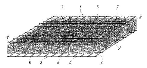
The building element shown in Figure 1 consists
of two flat wire grid mats 1 and 2, which are arranged
parallel to one another and at a predetermined distance
from one another. Each wire grid mat 1 and 2 consists of
a plurality of longitudinal wires 3 and 4 respectively
and of a plurality of cross wires 5 and 6 respectively,
which cross one another and are welded together at the
crossing points. The distance between the respective
longitudinal wires 3 and 4 and the respective cross wires
5 and 6 is selected in accordance with the static
regulations applicable to the building element. The
distances are preferably selected to be the same, for
example in the range from 50 to 100 mm, so that tie
longitudinal and cress wires lying next to one another in
each case form square meshes. Within the scope of the
invention the meshes of the wire grid mats 1, 2 may also
be rectangular and, for example, have short side lengths
of 50 mm and long side lengths in the range from 75 to
100 mm.
The diameters of the longitudinal and cross wires
are likewise selected in accordance with the static
requirements and are preferably in the range of 2 to
6 mm. Within the scope of the invention the surface of
the grid mat wires may be smooth or ribbed.
The two wire grid mats 1, 2 are joined together
by a plurality of web wires to form a dimensionally
stable spatial grid body. At their ends the web wires 7
are each welded to the wires of the two wire grid mats 1,
2, while within the scope of the invention the web wires
7 may either be welded to the respective longitudinal
wires 3, 4, as shown in the drawing, or be welded to the
cross wires 5, 6. The web wires 7 are arranged to slope
alternately in opposite directions, that is to say in
lattice fashion, so that the grid body is stiffened
against shear stresses.
The distances between the web wires 7 and the
distribution of the latter in the building element depend
on static requirements applicable to the building element
and for example amount to 200 mm along the longitudinal
wires and to 100 mm along the cross wires. The distances
of the web wires 7, 7' from one another in the direction
of the longitudinal wires 3, 4 of the grid mat and of the
cross wires 5, 6 of the grid mat expediently amount to a
multiple of the mesh pitch. The diameter of the web wires
is preferably in the range of 3 to 7 mm, while in the
case of building elements which have thin longitudinal
and cross wires the diameter of the web wires is
preferably selected to be larger than the diameter of the
longitudinal and cross wires.
Since the spatial grid body formed from the two
wire grid mats 1, 2 and the web wires 7 must not only be
dimensionally stable but, in the case of its preferred
use as a wall and/or ceiling element, must serve as a
spatial reinforcement element, that is to say has to take
shearing and compressive forces, the longitudinal and
cross wires are welded to one another, as is customary
for reinforcement mats, and the web wires 7 are also
welded to the grid mat wires 3, 4, 5, 6, while
maintaining a minimum strength of the weld nodes. In
order to be able to serve as a spatial reinforcement
element, the grid mat wipes 3, 4, 5, 6 and the web wires
7 must be made of suitable materials and have appropriate
mechanical strength values to be able to be used as
reinforcement wires for the wire grid mats 1, 2 which are
to serve as reinforcement mats, and, respectively, to be
used as reinforcement wires connecting the two wire grid
mats 1, 2.
Within the scope of the invention it is also
possible to connect the web wires 7, 7' at both their
ends by means of plastics cord knots or lashing, for
example. As an alternative the web wires 7, 7' may be
joined at one end in this manner and at their other end
by means of welding to the grid mat wires 3, 4, 5, 6.
_ g _
In the gap between the wire grid mats 1, 2 an
insulating body 8 is arranged at a predetermined distance
from the wire grid mats and centrally relative to the
latter, and series for thermal insulation and sound
deadening. The insulating body 8 consists for example of
foam plastics, such as polystyrene or polyurethane foam,
foam materials based on rubber and caoutchouc,
lightweight concrete, such as autoclave or aerated
concrete, porous plastics, porous substances based on
rubber and caoutchouc, pressed slag, pressed sludge,
gypsum plasterboard, cement-bound compressed boards
consisting of wood chips, jute, hemp and sisal fibres,
rice husks, straw waste, sugarcane waste, or mineral and
glass wool, corrugated cardboard, compressed waste paper,
bound stone chips, melted reusable plastics waste, tied
reed and bamboo canes.
The insulating body 8 may be provided with
predrilled holes to receive the web wires 7. The
insulating body 8 may also be provided on one or both
sides with a layer of plastics material or aluminium
serving as vapour barrier. The position of the insulating
body 8 in the building element is determined by the
obliquely extending web wires 7 which pass through the
insulating body 8.
The thickness of the insulating body 8 is freely
selectable and lies for example in the range from 20 to
200 mm. The distances from the insulating body 8 to the
wire grid mats 1, 2 are likewise freely selectable and
lie for example in the range from 10 to 30 mm. The
building element can be made in any desired length and
width, while because of the method of production a
minimum I ength o f 10 0 cm and standard widths o f 6 0 cm,
100 cm, 110 cm and 120 cm have proved advantageous.
As can be seen from the plan view of the building
element shown in Figure 2, at the edge of the building
element the longitudinal wires 3 and the edge
longitudinal wires 3' end in each case flush with the
edge cross wires 5', and the cross wires 5 and the edge
cross wires 5' end in each case flush with the edge
_ g _
longitudinal wires 3'. The same applies analogously to
the grid mat wires 4, 4', 6, 6' of the other wire grid
ma t 2 .
Figure 3 shows a side view of the building
element shown in Figure 1, viewed in the direction of the
set of cross wires. The web wires 7, which extend
obliquely alternately in opposite directions to one
another, here form a row and are in each case welded to
the corresponding longitudinal Wires 3 and 4, arranged
one above the other, of the wire grid mats 1 and 2
respectively.
Figures 4 and 5 each show an exemplary embodiment
with different angles between the web wires 7 and the
corresponding longitudinal wires 3, 4 of the wire grid
mats 1, 2, while in accordance with Figure 5 different
angles are also possible within a row of web wires within
a building element.
Figure 6 shows a building element in which the
web wires 7 in one row extend codirectionally obliquely
between the longitudinal wires 3 and 4 of the wire grid
mats 1, 2, while in the next row the web wires 7' shown
in dashed lines likewise extend codirectionally
obliquely, but in the opposite directional sense, between
the corresponding longitudinal wires, that is to say the
building element has a plurality of rows of
codirectionally oblique web wires with the directional
sense chaaging from row to row. Within the scope of the
invention the rows of web wires directed codirectionally
obliquely may also extend between the cross wires 5, 6 of
the wire grid mats 1, 2.
Figure 7 shows a building element having web
wires 7 extending obliquely in opposite directions for
each row, the distances between neighbouring web wires in
the row being so selected that the mutually facing ends
of the web wires come as close as possible to one
another, so that two web wires may optionally be welded
conjointly in one operation to the corresponding grid
wire.
Within the scope of the invention the web wires
- 10 -
7, as shown in Figure 8, may also be arranged at right
angles to the wire grid mats 1, 2. Since in this case the
position of the insulating body 8 in the grid body is
only inadequately fixed by the web wires 7, for the
purpose of fastening the insulating body 8 a plurality of
spacers 9 are provided, each of which is supported on the
corresponding grid mat wires of the wire grid mats 1, 2.
The spacers 9 are also used in building elements having
obliquely extending web wires 7 if, because of the nature
of the material of the insulating body, the fastening of
the latter in the grid body is not ensured by the web
wires. This applies for example to insulating bodies
consisting of tied reed or bamboo canes.
As Figure 9 shows, the insulating body 8 may also
be arranged asymmetrically to the two wire grid mats 1,
2. In this case the diameters of the grid wires 4, 4', 6,
6' of the wire grid mat 2 lying at the greater distance
from the insulating body 8 are advantageously larger than
the diameters of the grid wires 3, 3', 5, 5' of the wire
grid mat 1 lying closer to the insulating body 8.
In order to stiffen the grid body at its edges,
according to Figure 10 additional edge web wires 10 may
be provided, which preferably extend at right angles to
the wire grid mats 1, 2 and are welded to the
corresponding edge grid wires 3', 4', 5', 6' of the wire
grid mats 1, 2. The diameter cf the edge web wires 10 is
preferably equal to the diameter of the web wires 7, 7'.
In Figure 11 a building element according to the
invention is shown, in which at the side surfaces 11
extending parallel to the cross wires 5, 6 the insulating
body 8 does not end flush with the two wire grid mats
1, 2, but the latter project laterally beyond it. Hy means
of this embodiment, when two identical building elements
are joined together, the effect is achieved that the
insulating bodies of adjoining building elements can be
arranged without a gap, while the wire grid mats of the
two building elements overlap in each case and thus form
a bearing overlap joint.
The insulating body 8 may also end flush with the
- 11 -
inner wire grid mat 2 at its two side surfaces 11, and
only the wire grid mat 1 which will be on the outside in
practical use may project beyond it.
One or both of the wire grid mats may also
proj ect laterally beyond the insulating body 8 on all the
side surfaces. In these exemplary embodiments any edge
web wires 10 provided may be so arranged that they extend
outside the insulating body or laterally adjoin the
latter.
The longitudinal and cross wires of the wire grid
mats 1, 2 and also the web wires may have any desired
cross-section. The cross-sections may be oval,
rectangular, polygonal or, as illustrated in Figure 12,
square. The reference numerals of the corresponding wires
are 3" and 4" respectively for the square longitudinal
wires, 5" and 6" respectively for the square cross wires,
and 7" for the square web wires.
Figure 13 shows a building element which has a
two-part insulating body 8'. In this case the parts of
the insulating body may if necessary be bonded together
at their contact surfaces. The two parts of the
insulating body 8' enclose cavities 12 in order to save
material, but these may also be filled with other
materials, for example heapable, pourable and flowable
insulating materials, such as wood chips, foam plastic
chips, sand, plastic waste, rice waste, or straw waste.
The insulating body 8' may also consist of a plurality of
parts which can be joined together and for example have
a multilayer construction. It is in addition possible to
provide a one-piece insulating body 8 with cavities 12.
As schematically illustrated in Figures 14 and
15, there is applied to the outer wire grid mat 1
intended to form the outer side of the building element
an outer shell 13, for example of concrete, which adjoins
the insulating body 8, surrounds the outer wire grid mat
1 and together with the latter forms the bearing
component of the building element according to the
invention. The thickness of the outer shell 13 is
selected in accordance with the static, acoustic and
- 12 -
thermal requirements applicable to the building element,
and amounts for example to from 20 to 200 mm. If the
building element is used as a ceiling element, the
minimum thickness of the outer shell 13 must for static
reasons amount to 50 mm.
To the inner wire grid mat 2 intended to form the
inner side of the building element an inner shell 14 is
applied, which adjoins the insulating body 8, surrounds
the inner wire grid mat 2 and for example consists of
concrete or mortar. The thickness of the inner shell 14
is selected in accordance with the static, acoustic and
thermal requirements applicable to the building element
and amounts for exa..~iple to from 20 to 200 mm. The two
shells 13, 14 are preferably applied at the site where
the building element is used, for example sprayed on by
the wet or dry method.
Since the portions of the web wires 7, 7' which
lie in the inner region of the building element, and also
the edge web wires 10 when these are provided, are not
covered with concrete and are therefore exposed to
corrosion, the wires 7, 7' and 10 must be provided with
an anticorrosive layer. This is preferably achieved by
means of galvanising and/or coating of the wires 7, 7'
and 10. For reasons of cost it has proved advantageous
for galvanised wire already to be used, at least for the
web wires 7, 7', in the production of the grid body. The
wires 7, 7' and 10 may also be made of stainless steel
grades or ether non-corroding materials, for example alu-
minium alloys, which must be capable of being joined,
preferably by welding, to the grid wires of the wire grid
mats 1, 2. Within the scope of the invention, not only
the web wires 7, 7' and 10 but also the grid mat wires of
the wire grid mats 1, 2 may be provided with an anti-
corrosion layer or be made of stainless steel grades or
of other non-corroding materials.
For static reasons and/or in order to improve
sound deadening it may be necessary to provide the
building element, at least on one side, with a very thick
concrete shell having reinforcement in two layers. In
- 13 -
Figure 16a a part of a building element is shown which
has a very thick outer shell 13' of concrete, this outer
shell 13' being reinforced with an additional, outer
reinforcement mat 15 the distance between which and the
outer wire grid mat 1 is freely selectable in accordance
with the static requirements applicable to the building
element. The additional outer reinforcement mat 15
prevents cracking in the outer shell 13' caused by
temperature and shrinkage stresses.
For static reasons and/or in order to improve
sound deadening, the building element may also be
provided with a very thick inner shell 14', which is
reinforced either by an inner wire grid mat 2 or, as
shown in Figure 16b, with an inner wire grid mat 2 and an
additional, inner reinforcement mat 15'. The distance
between the additional inner reinforcement mat 15' and
the inner wire grid mat 2 is freely selectable in
accordance with the static requirements applicable to the
building element. The diameters of the grid wires of the
additional inner reinforcement mat 15' are preferably
larger than the diameters of the grid wires of the two
wire grid mats 1, 2 and lie, for example, in the range
from 6 to 6 mm. If the thick inner shell 14' is
reinforced only with the inner wire grid mat 2, the
diameters of the grid wires 4, 4', 6, 6' of the inner
wire grid mat 2 and of the web wires 7, 7' are preferably
larger than the diameters of the grid wires 3, 3', 5, 5'
of the outer wire grid mat 1 and lie, for example, in the
range from 5 to 6 mm.
The inner wire grid mat 2 and the additional
inner reinforcement mat 15' may be joined by a plurality
of spacer wires 24, which preferably extend at right
angles to the inner wire grid mat 2 and the additional
inner reinforcement mat 15' and the mutual lateral
spacing of which is freely selectable. The diameter of
the spacer wires 24 is preferably equal to the diameters
of the grid wires of the wire grid mats 1, 2.
Within the scope of the invention the additional
outer reinforcement mat 15 and the outer wire grid mat 1
- 14 -
may also be joined by spacer wires, which preferably
extend at right angles to the outer wire grid mat 1 and
to the additional outer reinforcement mat 15. These
spacer wires are arranged at selectable lateral distances
from one another and have diameters which are preferably
equal to the diameters of the grid wires of the two wire
grid mats 1, 2.
The thick concrete shells 13' and 14' provided
with reinforcement in two layers can also be poured with
site concrete at the place where the building element is
used, in which case the outer boundary of the concrete
shells 13', 14' is formed by shuttering (not shown).
As Figure 17 shows, there may be arranged on the
inner side of the building element, instead of the inner
concrete shell, a lining board 16 which lies on the inner
wire grid mat 2 and is fastened to a mounting aid device
17. The lining board 16 forms the r_on-bearing inner wall
of the building element and, as it has no static duties
to perform, can be made of light building material, such
as a plywood board, gypsum plasterboard and the like, and
have a decorative configuration complying with the
desired finish of the interior space. The mounting aid
device 17 is arranged between the insulating body 8 and
the inner wire grid mat 2 and consists for example of a
plurality of strips, which extend in the vertical
direction between the web wires when the building element
is used as a wal_ building element. The mounting aid
device 17 may, if necessary, be fastened to the wires 4
and 6 of the inner wire grid mat 2, for example by means
of staples (not shown), or to the insulating body 8, for
example by means of an adhesive coating. The mounting aid
device 17 must consist of suitable material, for example
wood, which ensures secure anchoring of the lining board
16 to the inner wire grid mat 2 lying therebetween. Hy
means of the configuration according to the invention the
lining board 16 is not fastened to the insulating body 8,
which obviously because of the nature of its material
does not permit secure attachment, but is firmly anchored
to or clamped fast against the inner wire grid mat 2.
- 15 -
In order to improve the adhesion to the two cover
surfaces 18 of the insulating body 8, 8' which face the
wire grid mats 1, 2 when the outer shell 13 and the inner
shell 14 of concrete are sprayed on, and to prevent the
material from flowing down undesirably during working,
the cover surfaces 18 of the insulating body 8, 8' may be
roughened. As shown in Figure 18, the cover surfaces may
be provided with depressions 19, which are formed in the
cover surfaces 18 of the insulating body, for example
with the aid of toothed wheels or rollers carrying spikes
or knobs on their periphery, during the production of the
building element.
Within the scope of the invention it is possible,
in accordance with Figure 19, to provide the insulating
body 8, 8' on its cover surfaces 18 with cross grooves
20, which extend in the horizontal direction when the
building element is used as a wall element. The
depressions 19 and the cross grooves 20 may also, within
the scope of the invention, already be produced during
the production of try insulating body.
With a view to improving the adhesion of the
outer concrete shell 13 to the insulating body 8, 8', as
illustrated in Figure 20 use may be made of a plaster
base grid 21, which lies on the cover surface 18 of the
insulating body 8, 8' and is fixed by the web wires 7 or
the insulating body 8, 8'. The plaster base grid 21
consists for example of a fine-mesh welded or woven wire
grid with a mesh wid~h of for example 10 to 25 mm and
wire diameters in the range from 0.8 to 1 mm. The plaster
base grid 21 may within the scope of the invention also
consist of expanded metal. Between the plaster base grid
21 and the cover surface 18 of the insulating body 8, 8'
an additional separating layer 22 may be arranged, which
consists for example of impregnated building paper or
cardboard and which at the same time serves as a vapour
barrier and is preferably joined to the plaster base grid
21.
In Figure 21 another exemplary embodiment of a
building element according to the invention is shown,
~~~~~.~d~
- 16 -
wherein two separating layers 22 are arranged in the
building element with selectable spacing from the
respective neighbouring wire grid mat 1 or 2, and are
spaced at a selectable distance from one another such
that a gap 23 is formed between the separating layers 22.
The separating layers 22 may for example consist of
cardboard, paperboard, plastics sheets, thin gypsum
plasterboard or concrete slabs with or without
reinforcement. The separating layers 22 are fastened in
position relative to the wire grid mats 1, 2 either by
the web wires 7 or with the aid of spacers. The gap 23
between the separating layers 22 is filled, either during
the production of the building element or only at the
site where the building element is used, with suitable
insulating material, whereby a central insulating layer
8" is formed in the building element. Since the
separating layers 22 accurately define the boundary
surfaces of the central insulating layer 8", for the
construction of the insulating layer it is possible to
use materials which do not need to be dimensionally
stable or self-supporting. The materials should, however,
be heapab_e, pourable or flowable and may for example
consist of plastics materials which can be foamed in
situ, plastics waste, rubber waste, wood waste, foam
plastics chips, sand, slag, expanded concrete, rice or
straw waste, or stone chips. In addition, a plaster base
grid 21 may be arranged on each of those surfaces of the
separating layers 22 which face the wire grid mats 1 and
2 respectively.
It is unders~ood that the exemplary embodiments
described can be variously modified within the scope of
the general principle of the invention; in particular it
is possible for the outer shell 13 and/cr the inner shell
14 or the lining board 16 to .e attached to the building
element already at the factory. The insulating body 8, 8'
and the central insulating Layer 8" as well as the
separating layers 22 may be made of flame-retardant or
non-flammable materials or may be impregnated or provided
with substances which make the insulating body 8, 8', the
- 17 -
central insulating layer 8" and the separating layers 22
flame-retardant or non-flammable. The insulating body 8,
8' and the separating layers 21 may in addition be
provided With a flame-retardant or non-flammable coat of
paint.
Within the scope of the invention it is further-
more possible for the insulating body 8, 8' or the
central insulating layer 8" to project laterally beyond
at least one wire grid mat 1, 2 at at least one side face
11 of the insulating body 8, 8' or of the central
insulating layer 8".