Note: Descriptions are shown in the official language in which they were submitted.
- 1- 2164463
UNIFORM SHELVING SYSTEM
FIELD OF THE INVENTION
The present invention relates to a totally modular shelving system
which is capable of being built in any desired configuration, and is easily
assembled and rli~m~ntled.
s
BACKGROUND OF THE INVENTION
Many types of modular shelving systems are available commercially.
The common elements of these systems include: 1) vertical posts; 2) hori-
zontal beams extending both lengthwise and widthwise; 3) connecting0 elements which connect the beams to the posts; and 4) shelving elements.
A truly modular system is one in which 1) the positions of the various
components are completely interchangeable; 2) the distances between the
vertical posts (and thus the size of the shelves) is easily and reversibly
altered; 3) the shelves can be extended in any direction; 4) there is only one
15 type of each component; and 5) the shelving unit can be easily assembled
and cli~m~ntled. Although the systems currently available claim to be
modular, in truth the number of permutations possible is limited due to
drawbacks in the design of the modular elements.
Thus, in some systems, the connector and horizontal beams form one
20 unit, as a result of which the beams cannot be replaced without dismantling
the connector from the vertical post. In other systems, the shelves and
~ - 2- 2164463
horizontal beams form one unit so that the shelves cannot be easily replaced.
In certain systems, the connections of the lengthwise and widthwise
horizontal beams to the posts differ, or there are dirrerellt types of shelves
for placement next to the posts ('end pieces') and away from the ends
5 ('center pieces'). In still other systems, the posts must be distanced one from
the other in order to insert or remove the horizontal beams. The above
disadvantages and others limit the modularity of these systems.
SUMMARY OF THE INVENTION
It is an object of the present invention to provide a shelving system
which is completely modular.
It is a further object of the present invention to provide a shelving
system which can be extended in all directions, forming an unbroken,
continuous shelf surface.
Additionally, it is an object of the present invention to provlde a
shelving system which is aesthetically pleasing to the eye.
According to the present invention, there is provided a modular
shelving system comprising: (1) vertical posts; (2) horizontal beams;
(3) side horizontal braces; (4) connectors capable of being mounted on the
vertical posts and having 1-4 identical ears protruding from the sides of the
connector capable of being coupled to the horizontal beams and braces; and
(5) shelf pieces which are positioned on the horizontal beams; wherein the
width of the side horizontal braces is substantially similar to the width of theconnectors.
In a preferred embodiment of the invention, the widths of the brace
and connector are substantially equal.
Further in accordance with the present invention, there is provided a
shelving system wherein the height of the side horizontal braces is
substantially similar to the height of the shelf pieces when the braces are
21 64463
- 3 -
coupled to the connectors and the shelf pieces are positioned on the
horizontal beams.
According to another aspect of the present invention, there is provided
a system wherein the height of the connectors is substantially similar to the
height of the side horizontal braces when the connectors are mounted on the
vertical posts and the braces are coupled to the connectors.
In a most preferred embodiment of the present invention, the
connectors, side horizontal braces and shelf pieces are all of the substantiallysame height, forming one continuous surface.
Although the present invention can be applied to various shelving
systems, a preferred application is to the shelving system described and
claimed in Applicant's co-pending Israel Patent Application No. 96339.
BRIEF DESCRIPTION OF THE DRAWINGS
The present invention will be better understood from the following
detailed description of preferred embodiments, taken in conjunction with- the
following drawings in which:
Fig. 1 is a perspective view of a shelving system according to a
preferred embodiment of the present invention;
Fig. 2 is a side view of a connector according to one embodiment of
the present invention;
Fig. 3 is a sectional side view of an adapter inserted into the end of a
horizontal beam, which is shown in a partial, cut-away view;
Fig. 4 illustrates the coupling of the adapter of Fig. 3 to the connector
of Fig. 2;
Fig. 5 is a partial side view of the shelving system, with part of the
horizontal brace cut away;
Fig. 6 is a plan view of a connector, split sleeve and nut mounted on
a verticle post;
4 21 64463
Figs. 7a and 7b are top sectional views of an alternate embodiment of
a connector;
Fig. 8 is a sectional view through line VIII-VIII of Fig. 1;
Fig. 9 is a top view through line IX-IX of Fig. 1;
Fig. 10 is a sectional view through line X-X of Fig. 1;
Fig. 11 is a perspective view of an extended shelving system according
to the present invention;
Figs 12a-c, 13a-b and 14a-b are perspective views illustrating various
methods for attaching perpendicularly positioned horizontal beams of the
shelving system of Fig. 11; and
Fig. 15 is a perspective view which illustrates the placement of a shelf
piece in the shelving system of Fig. 11.
DETAILED DESCRIPTION OF PREFERRED EMBODIMENTS
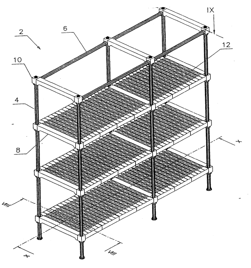
Reference is now made to Fig. 1, in which can be seen a two-unit
shelving system according to a preferred embodiment of the present
invention, generally designated 2. A number of vertical posts 4 are held
together by horizontal supports comprising lengthwise horizontal beams 6
and widthwise side horizontal braces 8. The horizontal beams and braces
are attached to the posts 4 by connectors 10, and a number of shelf pieces
12 are positioned on the beams 6. The shelf pieces are generally of standard
length and width, and the desired length of the system is obtained by using
the appropriate number of shelf pieces. The uppermost level of the system
is without shelf pieces in order to reveal the beams. The components of the
system can be made from metal or rigid plastic materials. Preferably, the
horizontal beams and vertical posts are made from metal, while all of the
rem~ining elements are made from plastic materials.
A connector 10 is illustrated in Fig. 2 as having a square shaped body
14 with projecting ears 16. The ears are of identical shape and can project
21 64463
from one, two, three or all of the sides of the body. The upper surface 18
of the connector is flat, and a slightly conical axial bore 20 extends through
the center of the connector. The diameter of the bore at its upper, narrower
end is slightly larger than the outer diameter of the vertical post 4. The
S connector can, of course, be of shapes other than square.
An adapter 22 inserted in the horizontal beam 6 is illustrated in Fig.
3. It comprises a cylindrical projection 24 extending from a shoulder 26.
The projection 24 has a diameter slightly smaller than the inner diameter of
the horizontal beam 6, so that it can be inserted into the ends of the beam,
10 as illustrated in the figure. The adapter will usually be secured to the beamby inserting the projection into the end of the beam and compressing the
beam end around the projection. This is done under pressure in the factory,
so that the beams are sold with the adapters already inserted in their ends.
The adaptors can also be secured to the beams by other means such as
15 screws, glue or compression bolts. A slot 28 in the shoulder 26 is
dimensioned so as to be tightly mounted on the ear 16 of the connector 10,
as illustrated in Fig. 4.
Fig. S illustrates the connection between the side horizontal brace 8 and
the connector 10. Referring to the cut-away left end of the brace 8, there is
20 shown a hook-like fastener 30 integral to the brace, coupled to the ear 16
of the connector. It can thus be seen that both the shoulder 26 of the
adapter 22 (Fig. 4) and the fastener 30 of the brace 8 are coupled to the ears
16 of the connector by lowering them onto the ears. This is advantageous
in situations where it is desired to replace the horizontal beams. There is no
25 need to tli~m~ntle the entire shelving, but rather the beams are simply lifted
up and removed, and the new beams are inserted.
Fig. 6 illustrates how the connector 10 is mounted on the post 4 in a
preferred embodiment. A split sleeve 32, is placed at a height on the post
where it is desired to position the shelves. In a preferred embodiment, the
21 64463
- 6 -
post has annular grooves 34 at spaced intervals along the length of the post,
and the split sleeve has a corresponding annular projection (not shown)
around the inner circumference of the sleeve. The sleeve is placed so that
the projection sits in the groove. The connector 10 is then mounted on the
S post and lowered onto the sleeve so that the sleeve enters the axial bore of
the connector. The grooves 34 act in counterbalance to the connector as it
is tightened on the sleeve, allowing the connector to be fixedly engaged to
the post by the sleeve. The grooves also contribute to supporting the weight
of the shelves, and stabilize the shelves from vibrations.
The connector can be further clamped in place by screwing on a nut
36 to the bottom side of the connector. The nut provides a counterbalance
to the connector when it is desired to remove a shelf piece or horizontal
beam by applying to them upwardly-directed blows.
The connector can be mounted on the post in other ways, as is well
15 known to the skilled man of the art. For example, the connector can be
screwed or bolted onto the post, thus obviating the need for a conical bore
and sleeve, as in the embodiment described above. Another variation is
illustrated in Figs. 7a and 7b, which show a split connector 10'. The two
lateral sections lO'a & lO'b of the connector are simply coupled together on
20 the post, so as to function as a whole connector. This type of connector can
be used with a split sleeve and a split nut, thus allowing replacement of a
connector without necessitating displacement of other connectors above or
below it.
After the horizontal braces and beams are assembled on the vertical
25 posts, the shelf pieces are placed on the beams as illustrated in Fig. 1. Fig.
8 shows a shelf piece 12 with inverted U-shaped hooks 38 on either end
supported by the horizontal beams 6. The shelf pieces can be easily placed
and removed without the need of tools.
21 64463
- 7 -
Fig. 9 illustrates a side horizontal brace 8 coupled by connectors 10 to
two vertical posts 4. Horizontal beams 6 extend from the connectors
perpendicularly to the brace. It can be seen that the width of the brace is
substantially equal to the widths of the connectors. This allows a shelf piece
5 to be positioned contiguously to the side brace 8. Thus there is no need for
having dirrerent types of shelf pieces, since the pieces positioned near the
posts do not have to 'wrap around' them.
In a preferred embodiment, the height of the side horizontal braces 8
when coupled to the connectors is subst~ntiAlly equal to the height of the
10 shelf pieces 12 when positioned on the horizontal beams, as illustrated in
- Fig. 10. In another preferred embodiment, the height of the connectors 10
when mounted on the vertical posts 4 is substantially equal to the height of
the side horizontal braces 8 when coupled to the connectors, as illustrated
in Fig. 5. In a most preferred embodiment, the heights of the connectors,
15 braces and shelf pieces are all substantially equal, thus forming a uniform,
continuous shelf surface within and between units, as illustrated in the three
levels of shelves in the system of Fig. 1. Other systems usually obtain this
effect by combining several elements, such as connectors, horizontal beams
and shelf pieces, into one integral unit. However, this results in less inter-
20 changeability between elements of the system. The advantage of the systemof the invention is that the uniform, continuous shelf surface is obtained
while each element remains independent, thus retaining the versatility of the
system.
Fig. 11 illustrates a shelving system according to an embodiment of the
25 present invention comprising several units extending in various directions.
This result is obtained by the use of connectors having two (40), three (42)
and four (44) ears. This demonstrates the exceptional versatility and
adaptability of the system of the invention.
2 1 64463
In the event that a first unit is positioned perpendicularly to a second
unit, as in the system illustrated in Fig. 11, the horizontal beams 46 of the
first unit may be perpendicularly attached to the intermediate area of the
beams 48 of the second unit by various methods.
S One method is illustrated in Figs. 12a-c. A coupler 50 is used to
connect between the end of a first horizontal beam 52 and the intermediate
area of a perpendicularly placed second horizontal beam 54. The coupler
50 comprises a short cylinder 56 having an outer diameter slightly smaller
than the inner diameter of the first beam 52. A short, cut-away cylinder 58
whose outer diameter is equal to that of the first beam 52 is attached to one
end of the cylinder 56. The outer end of the cylinder 58 is cut-away in a
semi-elliptical shape so that it can be mounted on the outer circumference
of the second beam 54.
The coupler is secured to the end of the first beam 52 by inserting the
short cylinder 56 into the end of the beam until the cut-away cylinder 58
abuts the~end of the first beam. The beam end is then compressed around the
coupler, as was done with the projection of the adapter 22 (see Fig. 3). The
opposite end of the coupler has a screw thread or nut (not shown) fixed in
the center of the cut-away cylinder 58. Two corresponding holes 60 are
drilled through the wall of the second beam 54 along its diameter, and a
screw 62 is inserted through the holes 60 and screwed into the screw thread
or nut to secure the second beam to the end of the first beam.
Figs.13a-b illustrate a second method for attaching two perpendicular-
ly placed beams. In this method, the coupler 64 comprises a short cylinder
66 similar to that of the coupler of Fig. 12. The cylinder is inserted into the
end of a first beam 52 as described above. In this method, however, the
cylinder projects from the lateral wall of an inverted U-shaped coupling
member 68. The inner diameter of the member is similar in size to the
~_ 9 2 1 64463
outer diameter of the beam 54, so that it can be securely mounted on the
circumference of the beam.
In the two methods described above, a special dedicated beam for the
perpendicular attachment of shelving units will usually be manufactured with
S the coupler inserted in one end under pressure. This somewhat limits the
modularity of the system. In the preferred method illustrated in Figs. 14 a-
b, the adapter 22 which was described above (and illustrated in Figs. 3 &
4) is used for the perpendicular attachment of shelving units.
The coupler 70 used in this method comprises an inverted U-shaped
coupling member similar to that illustrated in Fig. 13a, but having one
extended lateral wall 74 slightly longer than the height of the shoulder 26
of the adapter 22. An ear 76 projects from the outer surface of the extended
wall 74, similarly to the ears 16 projecting from the connector 10 (see Fig.
2). The adapter 22 is inserted into the end of a horizontal beam 52, as was
described above (Fig. 3). The member 70 is mounted on the circumference
of the beam 54, and the shoulder 26 of the adapter 22 is mounted on the ear
76 of the member, as described above with respect to the connector 10 (see
Fig. 4).
The advantage of this preferred method is that a beam having an
adapter inserted in its end can be used both for attachment to the end of a
second beam (by the connector) as well as for attachment to the intermediate
area of a second beam (by a coupler). It will be understood by the skilled
man of the art that methods of attachment other than those described above
may also be used.
The manner in which a shelf piece 12 can be mounted on a perpendic-
ular attachment site 78 as described above, is illustrated in Fig. 15. A small
slot 80 is cut in the vertical overhAn,~ing widthwise rim 82 of the shelf piece
12, at the location on the rim which will be mounted on the end of the beam
46 adjoining the attachment site 78. This slot 80 is in addition to the slots
21 64463
- 10 -
84 which are routinely cut in the ends of the lengthwise rims of the shelf
piece. The shelf piece is then mounted on the horizontal beam 48 with the
- end of the perpendicular horizontal beam 46 inserted through the slot 80.
Various modifications of the invention in addition to those shown and
5 described herein will become apparent to those skilled in the art. The scope
of the invention is therefore not to be construed as limited by the illustrativeembodiments set forth herein, but is to be determined in accordance with the
appended claims.