Note: Descriptions are shown in the official language in which they were submitted.
216~GO~
WO 94/29943 PCT/US94/06252
--1--
HEAD RAIL-MOUNTED MINI-BLIND ACTUATOR
FIELD OF THE INVENTION
The present invention relates generally to window covering peripherals and more
particularly to remotely-controlled mini-blind actuators.
BACKGROUND
Louvered blinds, such as LevellorR mini-blinds, are used as window coverings in a
vast number of business b~ lin~.c and dwellings. The typical blind has a number of
horizontal elongated parallelepiped-shaped louvers, i.e., rotationally-movable slats, which are
collectively oriented with their major surfaces parallel to the ground ("open") to permit light
to pass between adjacent slats, or with their major surfaces pe~yçn~ir~ r to the ground
("closed"), to block light from passing between adjacent slats, or any interm~di~te position
between open and closed. Stated dirrelc,llly, the slats can be rotated about their le;,l,ec~ive
longitl~-lin~l axes, i.e., about respective lines which are parallel to the ground, to open or
close the blind. Alternatively, the slats may be oriented vertically for rotation about their
respeclive longihl-lin~l axes (i.e., for rotation about respective lines that are perpentlirlll~r
to the ground), for opening and closing the blind.
Ordinarily, to provide for movement of the slats of a blind between the open andclosed positions, an elongated ~ct~ting baton is coupled to structure on the blind such that
when the baton is m~ml~lly rotated about its longibl~in~l axis, the slats move in unison
between the open and closed positions. It will accordingly be appreciated that by proper
manual operation of the baton, blinds can be used to effectively regulate the amount of light
which passes into the room in which the blind is located. Thus, blinds can be opened during
the day to permit snnlight to enter the room, or closed during particularly warm days to
prevent overheating of the room. Likewise, blinds can be closed at night for security
purposes, and to prevent heat within the room from dissipating through the window into the
cool evening air.
21G~ 09
WO 94/29943 PCT/US94/06252
,
- 2 -
While most existing m~ml~lly-operated blinds accordingly provide an effective means
for regulating the amount of light prop~g~ting into or out of a room, it is often advantageous
to provide for remote or automatic positioning of the blinds. For example, it would be
advantageous to provide for the automatic nighttim~ closing of blinds in a business premises,
for both security reasons and energy conservation, rather than to rely on personnel to
remember to m~nn~lly close all blinds before vacating the premises for the evening. Also,
remote operation of blinds would enable many invalid persons to regulate the amount of light
entering their rooms, without requiring the persons to m~ml~lly operate the ~ct~l~ting baton.
Not ~ul~risingly, several systems have been introduced for either lowering and raising
the slats of a blind, or for moving the slats between the open and closed positions. For
example, U.S. Patent No. 4,644,990 to Webb, Sr. et al. teaches a system for autom~ti~lly
moving a set of venetian-type window blinds in response to sensing a predetermined level
of sllnlight. Likewise, U.S. Patent No.3,860,055 to Wild teaches a system for autom~ti~lly
raising or lowering a shutter upon sensing a predelellllilled level of sllnlight Also, U.S.
Patent No. 4,096,903 to Ringle, III discloses a system for opening a blind, wheleill the
Ringle, III system is mounted in the head rail of the blind and opc~tes the blind in response
to an elec~lo",~gn~ti~ control signal.
Unfol Lunat~ly, the systems mentioned above, like many, if not most, automatic blind
control systems, are somewhat complicated in operation and cumbersome and bulky in
inct~ tion, and conceql~çntly are relatively e~ensive. For example, the Webb, Sr. et al.
system requires that a housing be mated with the blind structure for holding the various
components of the Fat~nt~d system, which includes, inter alia, ratchets, pawls, gears,
clutches, levers, and springs. In a similar vein, the Wild invention requires the use of,
among other components, a rather bulky gas-driven piston-and-cylinder to raise and lower
the shutter. Precisely how the piston-and-cylinder is mounted on an existing shutter assembly
is not dicc ~csed by Wild. The Ringle, III device consumes a relatively large amount of
power to sense its control signal, and thus exh~-~ctc its battery quickly, in part because of its
relatively complicated limit switch m.och~nicm and because Ringle, III does not provide any
electronic signal processing which would enable the Ringle, III device to sense a control
signal efficiently, with little power col~u.l.~ion.
WO 94129943 . 2 ~ ~ 4 fi ~ 9 PCT/US94/06252
Accordingly, it is an object of the present invention to provide a comparatively simple
device for opening and closing mini-blinds. It is another object of the present invention to
provide a remote control device for opening and closing blinds which is compact and easy
to install. Yet another object of the present invention is to provide a device for remotely and
automAti~lly opening and closing blinds. Still another object of the present invention is to
provide a device for remotely and automAtirAlly openillg and closing mini-blinds which
consumes relatively little power. Further, it is an object of the present invention to provide
a device for remotely and automAti~Ally opening and closing mini-blinds which is easy to use
and cost-effective to mAnllfa~tllre.
SUMMARY OF THE INVENTION
An actuator is disclosed for rotating the actuating baton of a mini-blind to open or
close the slats of the mini-blind. Typically, the mini-blind is mounted adjacent a surface,
e.g., a window sill.
The actuator of the present invention includes an electric motor which is operably
engaged with a coupling, and the coupling is engageable with the baton substantiAlly
anywhere along the length of the baton. A housing is provided for holding the motor, and
a fastening element is attArh~l to the housing and is connectable to a nearby surface, e.g.,
the window frame or the head rail of the blind, to prevent relative motion between the
surface and the housing. At least one direct current (dc) battery is mounted in the housing
and is electrically conn~octe~ to the motor for selectively e~ 5iGillg the motor to rotate the
baton.
Preferably, the rotor is conn~cte~l to a gear assembly, and the gear assembly in turn
is connlocte~ to the coupling. The coupling has a channel configured for closely receiving
the baton. In the presently l,iefelled embotlim~nt, the gear assembly includes a plurality of
reduction gears for causing the baton to rotate at a fraction of the angular velocity of the
rotor, and a rack gear for opeld~illg a limit switch to deactivate the motor when the blind is
in a predetermined configuration.
216460Y
WO 94/29943 ' PCT/US94/06252
In one presently plcfcllcd embodiment, a power switch is mounted in the housing and
is electrically connected between the battery and the motor. Preferably, the power switch
is an electronic circuit for sensing a control signal with comparatively little expenditure of
the battery energy. As intended by the present invention, the power switch has an open
configuration, wherein the electrical circuit from the battery to the motor is incomplete, and
a closed configuration, wherein the electrical circuit from the battery to the motor is
complete.
To provide for remote operation of the actuator, the power switch is moved between
the open and closed configuMtions by a control signal. In one embodiment, this control
signal is gelleldted by a daylight sensor which is electrically connect~d to the switch. The
daylight sensor generates the control signal in response to a predetermined amount of light
impinging on the daylight sensor.
Additionally, the control signal may be gell~ldted by a signal sensor which is
electrically connPcted to the power switch. The signal sensor gellelat~s the control signal
in response to a user co~ signal. To this end, a hand-held user COllllllZ~ signal
gene,dtor is provided which emits an optical user cc.lll-lland signal.
In another aspect of the present invention, a device is disclosed for moving theoperator of a window covering having slats to open or close the slats. The device includes
an actuator that has an electric motor and a coupling operably engaged with the motor. The
coupling contacts the ope.dt~,r to prevent rotational relative motion between the coupling and
the operator. A portable source of electrical power is included, and a control signal
generator is provided for geneldtillg a control signal to cause the source of electrical power
to be electrically co,~n~ with the actuator for enel~;i hlg the motor to move the opcldtor.
In yet another aspect of the present invention, a method is dlsclosed for moving the
slats of a mini-blind by rotating the actu~ting baton of the mini-blind. The method of the
present invention includes the steps of providing a motor, a dc battery, and a housing for
holding the battery and the motor, and then coupling the rotor of a motor with the baton.
Next, the housing is fastened to a nearby surface, e.g., a window sill or the head rail of the
WO 94/29943 216 ~ 6 0 ~9 PCT/US94/062~2
blind. Then, a predetermined electromagnetic signal is sensed to cause the battery to
energize the motor and thereby rotate the baton.
In still another aspect of the present invention, a device is disclosed for rotating the
operating baton of a blind to open and close the blind. As contemplated by the present
invention, the device includes an electric motor having a rotor and a direct current battery.
A coupling is operably engaged with the motor and is also coupled to the baton for
l,a~lsre~ g rotational motion of the rotor to the baton. A light sensor geneMtes a signal to
complete an electrical circuit between the battery and the motor when light having a
predetermined hltellsily hllpillges on the sensor. In accordance with the present invention,
the light sensor has a dark current equal to or less than about 10-5 alll~el~s.
In an alternate embodiment, an actuator is provided for rotating the tilt rod of a blind
having a head rail. The actuator includes a coupling which is engageable with the tilt rod
such that movement of the coupling causes rotation of the tilt rod. A reversible electric
direct current (dc) motor is operably engaged with the coupling to move the coupling, and
a dc battery is electrically co~ L~d to the motor to el~.gi;~e the motor. In this alternate
embodiment, a sensor detects a light signal and gel~lales a control signal in response to the
light signal. The control signal is sent to an electronic circuit which is electrically conn~cted
to the sensor and the battery for processing the control signal from the sensor to cause the
battery to energize the motor. The sensor and circuit are designed to sense the control signal
and process the signal in an energy efficient lllal~l~r to activate the motor, thereby conserving
battery energy and ma~imi7ing battery useful life.
Preferably, the sensor is a daylight sensor and the control signal is genel~ed by the
daylight sensor in response to a prede~ellllilled amount of light impinging on the daylight
sensor. Additionally, a signal sensor can gell~,ldte the control signal in response to a user
command signal. To this end, a hand-held user command signal generator can be provided
for selectively genel~Lillg the user command signal.
As intended by the pl~fcll, d embodiment, the electronic circuit has an edge detector
for delaying energi~tion of the motor for a predetermined time period after generation of
Wo 94/29943 21 G 16 ~ 9 PCT/US94/06252
the control signal by the daylight sensor. ~In other words, the edge detector prevents
operation of the blind in the event that a spurious light signal, e.g., from an automobile
h~llight momentarily impinges upon the daylight sensor at night.
Additionally, a m~ml~lly manipulable adjuster is engaged with the tilt rod. The tilt
rod has a closed position, wherein the blind is fully closed, and an open position, wheleh
the blind is open, and the open position is selectively established by manipulating the
adjuster.
In another aspect of the alternate embodiment, a device is disclosed for opening and
closing the slats of a window covering of the type having a head rail and an operator
disposed within the head rail. The device of the present invention includes an actuator which
has an electric motor and a coupling operably engaged with the motor, and the coupling
contacts the operator to preven~ rotational relative motion bcLweell the coupling and the
opelaLor. A source of electrical power and a control signal gellelator for genelaLing a control
signal are also provided, and an electronic circuit is electrically connected to the control
signal geneldLor and the source of electrical power for processing the control signal to cause
the source of electrical power to en~rgi~e the motor to move the operator. Preferably, the
electronic circuit includes at least one electronic component that is lcsponsive to the control
signal for energizing the actuator.
In yet another aspect of the ~lttorn~tt~ embodiment, a method is disclosed for moving
the slats of a blind by rotating the tilt rod of the blind. In accordance with the method of the
present invention, a motor, a dc battery, and an electronic circuit are provided for receiving
a control signal and proces.cin~ the control signal to cause the battery to ellelgi~e the motor.
With this purpose in mind, the rotor of the motor is coupled with the tilt rod, and a
predetermined electrom~gnPtic signal is sensed to genelaLe the control signal and cause the
electrical circuit between the battery and the motor to be completed to rotate the tilt rod.
In still another aspect of the present invention, an actuator is disclosed which is
couplable to an ope,d~ing component of a blind having an open configuration and a closed
configuration. The actuator includes a sensor for ~etecting a light signal and gelllldtillg a
wo 94129g43 ~ 1 fi 4 fi O 9 PCT/US94/06252
control signal in response thereto. Also, the actuator includes a coupling that is engageable
with the operating component of the blind such that movement of the coupling causes the
blind to move toward the open configuration or toward the closed configuration. A
reversible electric direct current (dc) motor is operably engaged with the coupling to move
the coupling, and a dc battery is provided for energizing the motor.
Furthermore, an electronic circuit is electrically conn~octed to the light sensor and to
the battery. As intended by the present invention, the electronic circuit processes the control
signal from the light sensor to cause the battery to ene,gi~e the motor. The electronic circuit
advantageously includes an edge detector for delaying ellelgi~ion of the motor for a
predetermin~cl time period after ge~ ion of the control signal by the sensor.
The details of the present invention, both as to its construction and operation, can best
be understood in lefelence to the accompanying drawings, in which like numerals refer to
like parts, and which:
BRIEF DESCRIPI ION OF THE DRAVVINGS
Figure 1 is a pelspe~;live view of the actuator of the present invention, shown in one
intended environment;
Figure 2 is another pel~l.e~ e view of the actuator of the present invention, shown
in one int~n~Pcl envirolllllellL;
Figure 3 is an exploded view of the actuator of the present invention;
Figure 4 is a perspective view of the gear assembly of the actuator of the present
invention, with portions broken away;
Figure 5A is a pel~pe~ e view of the main reduction gear of the actuator of the
present invention;
wo 94,2g943 2 ~ 6 ll ~ 0 3 PCT/US94/06252
Figure SB is a cross-sectional view of the rnain reduction gear of the actuator of the
present invention, as seen along the line 5B-SB in Figure SA;
Figure 6 is a p~ ec~ e view of the reed switch of the actuator of the present
invention;
Figure 7 is a sr~l~m~tir diagram of the electronic circuitry of the actuator of the
present invention;
Figure 8 is a perspective view of an alternate embodiment of the blind actuator
present invention, with portions of the head rail of the blind cut away for clarity; and
Figure 9 is a sc~ tir diagram of the electronic cil~;ui~l~r of the actuator shown in
Figure 8.
DETAILED DESCRIPTION OF THE PREFERRED EMBODIMENI
ReÇellillg initially to Figure 1, an actuator is shown, generally desi~n~t~cl 10. As
shown, the actuator 10 is in operable engagement with a rotatable ope~ lg baton 12 of a
mini-blind 14 having a plurality of louvered slats 16.
In the embodiment shown, the mini-blind 14 is a LevellorR-type mini-blind which is
mounted on a window frarne 18 to cover a window 20, and the baton 12 is rotatable about
its longit~ in~l axis. When the baton 12 is rotated about its longihldin~l axis, each of the
slats 16 is caused to rotate about its respective longitu-lin~l axis to move the mini-blind 14
between an open configuration, wherein a light passageway is established between each pair
of adjacent slats, and a closed configuration, wherein no light passageways are established
between adjacent slats.
While the embodiment described above ~ cllcses a mini-blind, it is to be understood
that the principles of the present invention apply to a wide range of window coverings that
have louvered slats.
Wo 94/29943 21~ 1~ 0 ~ PCT/US94/06252
As can be appreciated in reference to Figure 1, the baton 12 has a hexagonally-shaped
transverse cross-section, and the baton 12 is slidably engageable with a channel 22 of the
actuator 10. Accordingly, the actuator 10 can be slidably engaged with the baton 12
substantially anywhere along the length of the baton 12.
Figure 2 shows that the actuator 10 includes a f~ctening element, preferably a clip 23,
for f~ctening the actuator 10 to a head rail 24 of the mini-blind 14. In the embodiment
shown, the clip 23 engages the head rail 24 in a close hl~e,relellce fit to hold the actuator 10
onto the head rail 24. A support 25 is co.~ cled to or molded integrally with the actuator
10, and the support 25 extends below the head rail 24 and above the top slat 16a of the blind
14 to laterally support the actuator 10.
~ ltern~tively, the actuator 10 can be fastened to the window frame 18. In such an
embo~imPnt, a strip of tape (not shown) having adhesive material on both of its opposed
major surfaces is adhered to a portion of the actuator 10, and when the actuator 10 is gently
pressed against the window frame 18, the tape adheres to the window frame 18 to fasten the
actuator 10 to the window frame 18. It is to be understood that the actuator 10 ~llr~ /ely
may be ~tt~ch~cl to the frame 18 by bolts, screws, glue, nails, or other well-known factenPrs.
In cross-reference to Figures 2 and 3, the actuator 10 has a rigid solid plastic light
pipe 26 which, when the actuator 10 is mounted on the window frame 18 as shown, extends
between the window 20 and the mini-blind 14. Accordingly, a light passageway is
established by the light pipe 26 from the window 20 to the actuator 10. To facilitate the
tr~n~micsion of light through the light pipe 26, the light pipe 26 has an end 27 which has a
relatively rough, e.g., thirty micron (30,u) finish, while the rem~in-l.or of the surface of the
light pipe 26 has a three micron (3~) finish. It will be appreciated in lefe,e,~ce to Figures
1 and 2 that the light pipe 26 also provides lateral support to the actuator 10, in the same
manner as provided by the support 25.
A control signal generator, preferably a daylight sensor 28 (shown in phantom inFigure 3) is mounted on the actuator 10 by means well-known in the art, e.g., solvent
bonding. In accordance with the present invention, the daylight sensor 28 is in light
WO 94l2g9432 ~ 6 0 ~J PCT/US94/06252
communication with the light guide 26. -Also, the sensor 28 is electrically connected to
electronic components within the actuator 10 to send a control signal to the components, as
more fully disclosed below. Consequently, with the arrangement shown, the daylight sensor
28 can detect light that propagates through the window 20, independent of whether the mini-
blind 14 is in the open configuration or the closed configuration.
Further, the actuator 10 includes another control signal generator, preferably a signal
sensor 29, for receiving an optical, preferably visible red modulated user command signal.
Preferably, the user colnlllalld signal is genel~t~d by a hand-held user command signal
generator 31, which advantageously is a television remote-control unit. In one presently
ylc~lled embodiment, the generator 31 generates a pulsed optical signal having a pulse rate
of between about fifteen hundred microseconds and five thousand microseconds (1500,us-
5000~s).
Like the daylight sensor 28, the signal sensor 29 is electrir~lly conn~ct~l to electronic
components within the actuator 10. As ~ c~ e~l in greater detail below, either one of the
daylight sensor 28 and signal sensor 29 can genelaLe an electrical control signal to activate
the actuator 10 and thereby cause the mini-blind 14 to move toward the open or closed
configuration, as ayyluyliate.
Preferably, both the daylight sensor 28 and signal sensor 29 are light detectors which
have low dark ~;ull~llL~, to conserve power when the actuator 10 is deactivated. More
particularly, the sensors 28, 29 have dark ~;ull~llLs equal to or less than about 10-8 alllpe.es
and preferably equal to or less than about 2x10⁻⁹ anlye~s. In the p~esellLly yuerelled
embodiment, the daylight sensor 28 and signal sensor 29 are selected double-end type
phototransistors made by Sharp Electronics, part no. PT 460.
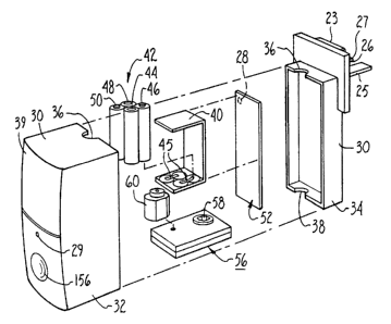
Referring now to Figure 3, the actuator 10 includes a hollow, generally
parallelepiped-shaped lightweight metal or molded plastic clamshell housing 30. As shown,
the housing 30 has a first half 32 which is snapyh~gly engageable with a second half 34.
Alternatively, the first half 32 of the housing 30 can be glued or bolted to the second half
34. Two openings 36, 38 are formed in the housing 30 to establish the channel 22 shown
WO 94/29943 ~ J ~i '1 t~ n .9 PCT/US94/06252
- 11 -
in Figure 1. As also shown in Figures 1 and 3, the housing 30 has a slightly convex front
surface 39.
As shown best in Figure 3, a molded plastic battery carriage 40 is positioned within
the housing 30. Preferably, the battery carriage 40 generally conforms to the inside contour
of the housing 30, i.e., the housing 30 "captures" the battery carriage 40 and holds the
carriage 40 stationary within the housing 30.
A power supply 42 is mounted in the battery carriage 40. In the ~lcfell~d
embodiment, the power supply 42 includes four type AA direct current (dc) ~lk~linP batteries
44, 46, 48, 50. The batteries 44, 46, 48, 50 are mounted in the battery carriage 40 in
electrical series with each other by means well-known in the art. For example, in the
embodiment shown, each of the batteries 44, 46, 48, 50 is positioned between respective
positive and negative metal clips 45 to hold the batteries 44, 46, 48, 50 within the carriage
40 and to establish an electrical path between the batteries 44, 46, 48, 50 and their respective
cllps.
Figure 3 further shows that an electronic circuit board 52 is positioned in the housing
30 adjacent the battery carriage 40. It is to be understood that an electrical path is
established between the battery clips and the electronic circuit board. Consequently, the
batteries 44, 46, 48, 50 are electrically connPctP-d to the electronic circuit board 52. The
electronic components of the circuit board 52 are di~c-lcsed in more detail in leferellce to
Figure 7 below.
Still l~fe.~ g to Figure 3, a lightweight metal or molded plastic gear box 56 is~tt~rhPd to or formed integrally with the battery carriage 40. The gear box 56 is formed
with a gear box opening 58 for receiving the baton 12 therein.
Figure 3 also shows that a small, lightweight electric motor 60 is ~tt~r~P~ to the gear
box 56, preferably by bolting the motor 60 to the gear box 56. In the presently pler~ ,d
embodimPrlt the motor 60 is a direct current (dc) motor, type FC-130-10300, made by
Mabuchi Motor America Corp. of New York. As more fully disclosed in reference to Figure
WO 94~299432 ~ 0 3 PCT/US94/06252
- 12 -
4 below, the gear box 56 holds a gear assembly which causes the baton 12 to rotate at a
fraction of the angular velocity of the motor 60. As further discussed below more fully in
reference to Figure 7, the motor 60 can be energized by the power supply 42 through the
circuit board 52. -
~
Now lcfelling to Figures 4, 5A, SB, and 6, the details of the gear box 56 can beseen. As shown best in Figure 4, the gear box 56 includes a plurality of lightweight metal
or molded plastic gears, i.e., a gear assembly, and each gear is rotatably mounted within the
gear box 56. In the pleselllly plefe,lcd embodiment, the gear box 56 is a clamshell structure
which includes a first half 62 and a second half 64, and the halves 62, 64 of the gear box 56
are snappingly engageable together by means well-known in the art. For example, in the
embodiment shown, a post 66 in the second half 64 of the gear box 56 engages a hole 68 in
the first half 62 of the gear box 56 in an illlel~lence fit to hold the halves 62, 64 together.
Each half 62, 64 includes a ~cspecli~re opel~,llg 70, 72, and the opel~illgs 70, 72 of the
gear box 56 establish the gear box opel~lg 58 (Figure 3) and are coaxial with the channel
22 of the housing 30 for slidably receiving the baton 12 thele~ ugh.
As shown in Figure 4, a motor gear 74 is conn~ctecl to the rotor 76 of the motor 60.
In turn, the motor gear 74 is engaged with a first reduction gear 78, and the first reduction
gear 78 is engaged with a second reduction gear 80.
As shown in Figure 4, the second reduction gear 80 is engaged with a main reduction
gear 82. To closely receive a hexagonally-shaped baton, the main reduction gear 82 has a
hexagonally-shaped channel 84. As int~n~ed by the present invention, the ch~nn~ol 84 of the
main reduction gear 82 is coaxial with the ol)elli,l~ 70, 72 (and, thus, with the gear box
opening 58 of the gear box 56 shown in Figure 3). Consequently, the channel 84 of the
main reduction gear 82 is also coaxial with the channel 22 of the housing 30, for receiving
the baton 12 thelc~ ugh.
It can be appreciated in lcfelcnce to Figure 4 that when the main reduction gear 82
is rotated, and the baton 12 is engaged with the channel 84 of the main reduction gear 82,
WO 94/29943 2 ~ 6 ~ fi 0 9 PCT/US94/06252
the sides of the channel 84 contact the baton 12 to prevent rotational relative motion between
the baton 12 and the main reduction gear 82. Further, the reduction gears 78, 80, 82 cause
the baton 12 to rotate at a fraction of the angular velocity of the motor 60. Preferably, the
reduction gears 78, 80, 82 reduce the angular velocity of the motor 60 such that the baton
12 rotates at about one revolution per second.
It is to be understood that the channel 84 of the main reduction gear 82 can have other
shapes suitable for conforming to the shape of the particular baton being used. For example,
for a baton (not shown) having a circular transverse cross-sectional shapes, the channel 84
will have a circular cross-section. In such an embodiment, a set screw (not shown) is
threadably engaged with the main reduction gear 82 for extending into the channel 84 to abut
the baton and hold the baton stationary within the channel 84. In other words, the gears 74,
78, 80, 82 described above establish a coupling which operably engages the motor 60 with
the baton 12.
In cross-lererel~ce to Figures 4, SA, and 5B, the main reduction gear 82 is formed
on a hollow shaft 86, and the shaft 86 is closely received within the opening 70 of the first
half 62 of the gear box 56 for rotatable motion therein. Also, a first travel limit reduction
gear 88 is formed on the shaft 86 of the main reduction gear 82. The first travel limit
reduction gear 88 is engaged with a second tMvel limit reduction gear 90, and the second
travel limit reduction gear 90 is in turn engaged with a third travel limit reduction gear 92.
Figure 4 best shows that the third travel limit reduction gear 92 is engaged with a
linear rack gear 94. Thus, the main reduction gear 82 is coupled to the rack gear 94 through
the travel limit reduction gears 88, 90, 92, and the rotational speed (i.e., angular velocity)
of the main reduction gear 82 is reduced through the first, second, and third travel limit
reduction gears 88, 90, 92. Also, the rotational motion of the main reduction gear 82 is
tr~n~l~fed into linear motion by the operation of the third travel limit reduction gear 92 and
rack gear 94.
Figure 4 shows that the second reduction gear 80 and second and third travel limit
reduction gears 90, 92 are rotatably engaged with respective metal post axles 80a, 90a, 92a
216~609
W O 94/29943 . PCTnJS94/06252
-14-
which are anchored in the first half 62 of the gear box 56. In contrast, the first reduction
gear 78 is rotatably engaged with a metal post axle 78a which is anchored in the second half
64 of the gear box 56.
Still lere,ling to Figure 4, the rack gear 94 is slidably engaged with a groove 96 that
is formed in the first half 62 of the gear box 56. First and second travel limiters 98, 100 are
connPcted to the rack gear 94. In the embodiment shown, the travel limiters 98, 100 are
threaded, and are threadably engaged with the rack gear 94. Alternatively, travel limiters
(not shown) having smooth surfaces may be slidably engaged with the rack gear 94 in an
interference fit thelewi~l, and may be m~nll~lly moved relative to the rack gear 94.
As yet another alternative, travel limiters (not shown) may be provided which are
formed with respective detents (not shown). In such an embodiment, the rack gear is for ned
with a channel having a series of openin~,~ for receiving the detents, and the travel limiters
can be manipulated to engage their detents with a preselected pair of the openings in the rack
gear channel. In any case, it will be appreciated that the position of the travel limiters of the
present invention relative to the rack gear 94 may be m~nll~lly adjusted.
Figure 4 shows that each travel limiter 98, 100 has a respective abu~ lll surface 102,
104. In cross-ler~.ellce to Figures 4 and 6, the abutment surfaces 102, 104 can contact a
reed switch 106 which is mounted on a base 107. The base 107 iS in turn anchored on the
second half 64 of the gear box 56. As intended by the present invention, the reed switch 106
inrludes electrically conductive, preferably beryllium-copper first and second spring arms
108, 112 and an electrically conductive, preferably beryllium-copper center arm 110. As
shown, one end of each spring arm 108, 112 is ~ chP~ to the base 107, and the opposite
ends of the spring arms 108, 112 can move relative to the base 107. As also shown, one end
of the center arm 110 is ?~tt~rh~ to the base 107.
When the main reduction gear 82 has rotated sufficiently counterclockwise, the
abutment surface 102 of the first travel limiter 98 contacts the first spring arm 108 of the
reed switch 106 to urge the first spring arm 108 against the stationary center arm 110 of the
reed switch 106. On the other hand, when the main reduction gear 82 has rotated clockwise
21fi~6~9
WO 94t29943 PCT/US94/06252
- 15 -
a sufficient amount, the abutment surface 104 of the second travel limiter 100 contacts the
second spring arm 112 of the reed switch 106 to urge the second spring arm 112 against the
stationary center arm 110 of the reed switch 106.
Figure 6 best shows that an electrically conductive, preferably gold-plated contact 114
is deposited on the first spring arm 108, and electrically conductive, preferably gold-plated
contacts 116a, 116b are deposited on opposed surfaces of the center arm 110. Also, an
electrically conductive, preferably gold-plated contact 118 is deposited on the second spring
arm 112.
Thus, when the first spring arm 108 is urged against the center arm 110, the contact
114 of the first spring arm 108 contacts the contact 116a of the center arm 110 to complete
an electrical circuit. On the other hand, when the second spring arm 112 is urged against
the center arm 110, the contact 118 of the second spring arm 112 contacts the contact 116b
of the center arm 110 to complete an electrical circuit. It can be appreciated in ~Çe~llce to
Figure 4 that the reed switch 106 is electrically conn~octecl to the circuit board 52 (Figure 3)
via an electrical lead 119.
.
As more fully disclosed below in lefelence to Figure 7, the completion of either one
of the electrical circuits ~ C -c~ed above causes the motor 60 to deellel~"~e and consequently
stops the rotation of the main reduction gear 82 and, hence, the rotation the baton 12. Stated
dirre~clllly, the travel limiters 98, 100 may be m~ml~lly adjusted relative to the rack gear 94
as applop,iate for limiting the rotation of the baton 12 by the actuator 10.
Refe~ lg briefly back to Figure 4, spacers 120, 122 may be molded onto the halves
62, 64 for structural stability when the halves 62, 64 of the gear box 56 are snapped
together.
Now lefe.lillg to Figure 7, the details of the electrical circuitry contained on the
circuit board 52 may be seen. In overview, the electrical circuit board 52 includes a pulse
modulation detector 130 and a beam and manual direction controller 132 for processing the
user command signal generated by the user command signal generator 31 and sensed by the
216~609
WO 94/29943 PCT/US94/06252
signal sensor 29 (Figure 1) for opening and closing the blind 14. Also, to operate the blind
14 in response to a predetermined level of sunlight as sensed by the daylight sensor 28
(Figure 3), the circuit board 52 includes a daylight detector 134, a daylight direction
controller 136, and an edge detector 138. The edge detector 138 prevents operation of the
blind 14 in response to spurious light signals, e.g., automobile h~light~. Additionally, the
circuit board 52 has an output amplifier 140 for pow~fillg the motor 60 shown in Figure 3.
For clarity of disclosure, the ~ c~lssion below focusses on the salient Con~o~ of
the electrical circuit board 52. Table 1 below, however, sets forth the values of all of the
resistors and capacitors of the circuit board 52 of the plcfellcd embodiment.
Figure 7 shows that the pulse modulation detector 130 includes a first type 4093Schmidt trigger 142 that is electrically conn~cte~ to the signal sensor 29 for receiving the
pulse mod~ tecl detection signal thelcrlulll. From the first trigger 142, the signal is sent to
first and second stages 144, 146 of a type 4538 activity sensor, and from thence to a first
type 4093 NAND gate inverter 148. The NAND gate hl~ el 148 functions as an inverter,
geneldlillg a FALSE signal output signal from two TRUE input signals and a TRUE signal
output otherwise. From the NAND gate inverter 148, the signal is sent through a first type
lN4148 diode 150 to a capacitor C2. Also, from the second stage 146, the signal is sent
through a second type lN4148 diode 152 to a capacitor C8.
When the first trigger 142 senses a pulsed optical signal from the signal sensor 29,
the first trigger 142 generates an output signal having the same pulse rate as the optical signal
from the signal sensor 29. When the output signal of the trigger 142 has a pulse rate greater
than 5000~4s, the output signal of the first stage 144 is FALSE. Consequently, the output of
the NAND gate inverter 148 is TRUE. A TRUE output signal from the NAND gate illVCl lel
148 m~int~in~ a positive voltage on the capacitor C2. As more fully ~i~c~lsse~ below, when
a positive voltage is m~int~in~d on the capacitor C2, energi~ation of the motor 60 is
prevented.
Additionally, when the output signal of the first trigger 142 has a pulse rate less than
fifteen thousand microseconds (1500~s), the output signal of the second stage 146 will be
WO 94/29g43 215 ~ ~ O 9 PCT/US94/06252
FALSE. Consequently, the capacitor C8 discharges, which causes the input signal of the
NAND gate inverter 148 from the second stage 146 to become FALSE. In response, the
output of the NAND gate inverter 148 is TRUE, which, as tli~cucse~ above, m~int~in~ a
positive voltage on the capacitor C2 to prevent energization of the motor 60.
In contrast, when the output signal of the first trigger 142 has a pulse rate between
fifteen hundred microseconds and five thousand microseconds (1500,us-5000~s) (in~ir~ting
reception by the signal sensor 29 of a proper optical control signal having a pulse rate of
between 1500~s-5000,us), the output signals of both the first and second stages 144, 146 are
TRUE. In turn, the output signal of the first NAND gate inverter 148 is FALSE, permitting
the capacitor C2 to discharge and thereby permit enelgiGdtion of the motor 60.
The skilled artisan will appreciate that the values of R2 and C2 are selected to require
that the output signal of the first NAND gate inverter 148 remains FALSE for at least three
hundred thirty milli~econds (330ms) before the capacitor C2 fully discharges to enable
enelgi~dLion of the motor 60. The skilled artisan will further appreciate that when a two-
position switch 154 having an "ON" position and an "OFF" position (Figures 1 and 7) is
m~m-~lly moved to the "OFF" position, voltage from the power supply 42 is con~luct~l to
the capacitor C2 to prevent the automatic el~rgiza~ion of the motor 60 described above. The
motor 60 may nevertheless be e~ gized when the two-position switch 154 is in the "OFF"
position, however, by m~nll~lly deplessillg a thumbswitch 156 (Figures 1 and 7), as more
fully disclosed below.
Figure 7 shows that the beam and manual direction controller 132 includes a second
type 4093 NAND gate h~v~ller 158, the input signal of which is the output signal of the first
NAND gate inverter 148. Upon receipt of a "FALSE" input signal from the first NAND
gate inverter 148 (in~ic~ting reception by the signal sensor 29 of a proper optical control
signal having a pulse rate of between 150011s-5000,us for at least 330ms), the second NAND
gate inverter 158 gene,dtes an output clocking signal. Also, Figure 7 shows that when the
thumbswitch 156 is de~,~ssed, a "FALSE" input signal is sent to the second NAND gate
inverter 158, and an output clocking signal is consequently geneldted by the inverter 158.
216~09
WO 94/29g43 PCT/US94/06252
The output clocking signal of the second NAND gate inverter 158 is sent in turn to
a type 4013 "D" motor run flip-flop 160. As shown in Figure 7, the flip-flop 160 is in the
so-called "toggle" configuration (i.e., pin 2 of the flip-flop 160 is electrically connected to
its pin 5). Accordingly, the flip-flop 160 changes state each time it receives a clocking
signal.
Figure 7 shows that the motor run flip-flop 160 is electrically conn~cte~l to a type
4013 "D" motor direction flip-flop 162. Like the motor run flip-flop 160, the motor
direction flip-flop 162 is in the "toggle" configuration.
In accordance with the present invention, the motor run flip-flop 160 genelates eithe
a "motor run" or "motor stop" output signal, while the motor direction flip-flop 162
geneldL~s either a "clockwise" or "counterclockwise" output signal. As ~iccllsce~ above,
each time the motor run flip-flop 160 receives a clocking signal, it changes state. Also, each
time the motor run flip-flop 160 is reset to a "stop motor" state, it toggles the motor
direction flip-flop 162 via a line 163 to change state.
Thus, with the motor direction flip-flop 162 initially in the clockwise state, to cause
the motor run flip-flop 160 to gelleldt~ a "motor run" output signal, the user signal ge,~ldtor
31 (Figure 1) is manipulated to gelleldL~ a first user collllllalld signal (or the thumbswitch 156
is depressed). Then, to cause the motor run flip-flop 160 to gellcldl~ a "motor stop" output
signal, the user signal generator 31 is manipulated to generate a second user command signal
(or the thumbswitch 156 is again depressed).
Upon receiving the second clocking signal, the motor run flip-flop 160 toggles the
motor direction flip-flop 162 to change state (i.e., to coun~elclockwise). Then, manipulation
of the user signal gel-eld~or 31 to g~lleldL~ yet a third user command signal (or again
depressing the thumbswitch 156) causes the motor run flip-flop to generate a "motor run"
signal. Yet a fourth signal causes the motor 60 to again stop, and so on.
Additionally, the state of the motor run flip-flop 160 is caused to change when the
motor 60 reaches its predetermined clockwise or counterclockwise limits of travel, as
216~9
wo 94/29943 PCT/uS94/06252
- 19 -
established by the positions of the travel limiters 98, 100 relative to the rack gear 94 (Figure
4). This prevents continued energization of the motor 60 after the motor 60 has reached a
travel limit, as sensed by the reed switch 106.
In describing this means of çh~nging the state of the motor run flip-flop 160 inresponse to travel motion limitations, the motor direction flip-flop 162 generates either a
clockwise ("CW") output signal or a counterclockwise ("CCW") output signal, as mentioned
above and in-lic~tP~ in Figure 7 by lines CW and CCW. In the presently prefell~dembodiment, clockwise rotation of the motor 60 colle~ol~ds to opening the blind 14, while
counterclockwise rotation of the motor 60 corresponds to closing, i.e., ~hllltin~, the blind 14.
In further disclosing the coopeMtion of the motor direction flip-flop 162 with the
motor run flip-flop 160, the "CW" output signal of the motor direction flip-flop 162 is sent
to a first type 4093 limit switch NAND gate 164, whe,eas the "CCW" output signal of the
motor direction flip-flop 162 is sent to a second type 4093 limit switch NAND gate 166.
The output signals of the first and second limit switch NAND gates 164, 166 are sent in turn
to a third type 4093 limit switch NAND gate 168, and the output signal of the third limit
switch NAND gate 168 is sent to the motor run flip-flop 160.
Figure 7 also shows that the first and second limit switch NAND gates 164, 166
receive respective upper limit reached ("USW") and lower limit reached ("LSW") input
signals. As shown in Figure 7, the "USW" signal is ge~ dted by a type 4093 USW NAND
gate 170, and the "LSW" signal is gel~ ed by a type 4093 LSW NAND gate 172.
Both NAND gates 170, 172 receive input signals from a type 4093 direction NAND
gate 174. In turn, the direction NAND gate 174 receives an input signal intlic~ting the
direction of actual rotation of the motor 60 (i.e., the "motor run CW" signal or the "motor
run CCW" signal. In Figure 7, the "motor run CW" signal has been designated "DRCW",
and the "motor run CCW" signal has been ~esign~tPcl"DRCCW", and the gen~ ion of both
the "DRCW" and "DRCCW" signals is ~ cll~s-p~l more fully below.
wO 94/2994~ 9 PcT/uss4/06252
- 20 -
The output signal of the direction NAND gate 174 is always "TRUE", unless it senses
that the motor 60 has been simultaneously given both a "motor run CW" ("DRCW") signal
and a "motor run CCW" ("DRCCW") signal, in which case the output signal of the direction
NAND gate is "FALSE". Thus, the "DRCCW" and "DRCW" signals are gated as described
above to prevent d~m~ging the output amplifier 140 if the motor 60 is erroneously
comm~n-lecl to ~imlllt~n~ously rotate in both the clockwise and counterclockwise directions.
Additionally, the USW NAND gate 170 receives an input signal from the reed switch
106 when the abutment surface 102 of the travel limiter 98 (Figure 4) urges the first arm 108
against the center arm 110 of the switch 106, indic~ting that the rack gear 94 (and, hence,
the motor 60) has reached the predetermin~d upper, i.e., clockwise, limit of travel. Also,
the LSW NAND gate 172 receives an input signal from the reed switch 106 when theabutment surface 104 of the travel limiter 100 (Figure 4) urges the second arm 112 against
the center arm 110 of the switch 106, intlir~ting that the rack gear 94 (and, hence, the motor
60) has reached the pre~L~ ;n~d lower, i.e., counterclockwise, limit of travel.
Accordingly, upon receipt of the appl~liate signal from the reed switch 106, theUSW NAND gate 170 gelleldles the USW signal. Likewise, upon receipt of the a~ropliate
signal from the reed switch 106, the LSW NAND gate 172 genelates the LSW signal.
Further, independent of the position of the reed switch 106, in the event that the
output signal of the direction NAND gate 174 is "FALSE", the USW NAND gate 170
gene.dles a USW signal, and the LSW NAND gate 172 geneldles a LSW signal.
Consequently, the motor 60 will be caused to stop if the direction NAND gate 174 senses
the simll~t~nPous existence of both a "motor run CW" (i.e., a "DRCW") signal and a "motor
run CCW" (i.e., a "DRCCW") signal.
As ~ cllsse~ above, the LSW and USW signals are sent to the first and second limit
switch NAND gates 164, 166, which geneldl~ input signals to the third limit switch NAND
gate 168. In turn, the third limit switch NAND gate 168 sends a clocking signal to the
motor run flip-flop 160 to cause the motor run flip-flop 160 to change state, i.e., to the
"motor off" state.
wo 94/29943 2 I 6 4 6 0 ~ PCT/US94/062~2
Accordingly, when the motor 60 is rotating clockwise and the upper (i.e., clockwise)
limit of rotation is reached, the reed switch 106 generates a signal which is sent via the
following path to change the state of the motor run flip-flop 160 to cause the motor 60 to
stop: USW NAND gate 170, first limit switch NAND gate 164, third limit switch NAND
gate 168.
Likewise, when the motor 60 is rotating counterclockwise and the lower (i.e.,
counterclockwise) limit of rotation is reached, the reed switch 106 gel~lates a signal which
is sent via the following path to change the state of the motor run flip-flop 160 to cause the
motor 60 to stop: LSW NAND gate 172, second limit switch NAND gate 166, third limit
switch NAND gate 168.
Figure 7 additionally shows that the "USW" and "LSW" signals are also sent to the
motor direction flip-flop 162 via le;,~e~ /e resistors R22, R23 to reset the flip-flop 162 to
the appropliate state. Stated dirr.,.~lllly, the "USW" signal is sent to the motor direction flip-
flop 162 via resistor R22 to reset the flip-flop 162 to the counterclockwise state, and the
"LSW" signal is sent to the motor direction flip-flop 162 via resistor R23 to reset the flip-
flop 162 to the clockwise state, when the ap~,lo~fldle travel limits have been reached.
The output signals of the flip-flops 160, 162 are each gated to type 4093 flip-flop CW
and CCW NAND gates 176, 178. More specifically, both output signals of the motor run
flip-flop 160 are gated to the NAND gates 176, 178, whereas only the "CW" output signal
of the motor direction flip-flop 162 is gated to the CW NAND gate 176, and the "CCW"
signal from the motor direction flip-flop 162 is gated to the CCW NAND gate 178.
As intended by the present invention, the flip-flop CW NAND gate 176 gel~ldtes a"motor run CW" (i.e., the "DRCW") output signal only when the motor run flip-flop 160
inputs a "motor run" signal to the CW NAND gate 176 and the motor direction flip-flop 162
inputs a "CW" signal to the NAND gate 176. Likewise, the flip-flop CCW NAND gate 178
generates a "motor run CCW" (i.e., "DRCCW") output signal only when the motor run flip-
flop 160 inputs a "motor run" signal to the CCW NAND gate 178 and the motor direction
flip-flop 162 inputs a "CCW" signal to the NAND gate 178.
216~0~
wo 94/29943 PCT/US94/06252
- 22 -
Now referring to the daylight detector 134 shown in Figure 7, the purpose of which
is to energize the motor 60 to open or close the blind 14 upon detection of a predetermined
level of light that is present at the daylight sensor 28, the daylight sensor 28is electrically
connPcted to a first type 2N3904 transistor Q2. Accordingly, when light impinges upon the
daylight sensor 28, the sensor 28 sends a signal to the transistor Q2.
If desired, energization of the motor 60 in response to signals geneld~ed by thedaylight sensor 28 can be disabled by applopliately manipulating a two-position daylight
disable switch 180. The switch 180 has an "AUTO" position, whel~ automatic operation
of the actuator 10 in response to signals from the daylight sensor 28is enabled, and an
"OFF" position, wherein automatic operation of the actuator 10 in response to signals from
the daylight sensor 28is disabled.
After receiving the signal from the daylight sensor 28, the first transistor Q2 turns on,
and consequently causes a first type 2N3906 transistor Q1 to turn on. The output signal of
the second transistor Q1 is sent via a resistor R4 to the base of the first transistor Q2, to
establish a hysterisis-based electronic signal latch. Also, the output signal of the second
transistor Qlis sent to a type 4093 light NAND gate 182. Whenever the light NAND gate
182 receives a signal from the second transistor Ql, the NAND gate 182 changes state.
Figure 7 shows that the output signal genelaled by the light NAND gate i~lvelLer 182
is sent to the so-called "D" input ports of type 4013first and second stages 184, 186 of the
daylight direction controller 136. The output signals of the stages 184, 186 are "motor run
CW("DRCW") and "motor run CCW" (DRCCW") signals, and are in turn respectively sent
to type 4093CW and CCW NAND gate motor controllers 188,190 of the output amplifier
Cil~ui~l~ 140.
To genel~te their motor run output signals, the stages 184, 186 of the daylight
direction controller 136 must also receive input signals from the edge detector 138. As
intended by the present invention, the edge detector 138 functions to prevent automatic
operation of the blind 14 in the ~lesellce of detection signals generated by the daylight
detector 136 in response to spurious light signals, e.g., automobile hP~fllight.~ at night.
wo 94/29943 2 ~ fi ~ ~ n ~ PCT/US94/06252
- 23 -
Figure 7 shows that the edge detector 138 includes a type 4077 exclusive exclusive
NOR gate 194. As shown, the exclusive NOR gate 194 receives a first input signal directly
from the light NAND gate 182 and a second input signal which origin~te~ at the NAND gate
182 and which is passed through the network established by a resistor R13 and a capacitor
C4. With this a"allgelllent, the exclusive NOR gate 194 geneldt~s a positive pulse output
signal each time the light NAND gate 182 changes state.
As further shown in Figure 7, the output signal of the exclusive NOR gate 194is sent
to a type 4020 fourteen (14) stage binary counter 196. The counter 196is associated with
an oscillator 198 that includes a type 4093 NAND gate 199, and the counter is also
associated with first and second type 4077 exclusive NOR gate inverters 200, 202. The
exclusive NOR gate inverters 200, 202 cooperate to ensure correct phasing of the oscillator
output clocking signal.
As disclosed above, when a detection signal is received from the light NAND gate182 of the daylight detector 134, this signal is sent to the exclusive NOR gate 194 in the
edge detector 138 and to the first and second stages 184, 186 in the daylight direction
controller 136. The first and second stages 184, 186, however, do not imm~ tely ge,~,dle
an output signal in response.
Tn~te~l, the exclusive NOR gate 194 imm~ tely sends an output signal to the
counter 196. In response, the counter 196 enables the oscillator 198 to generate output
clocking signals, and the counter 196 commences counting the output clocking signals from
the oscillator 198 until the first ~ een(13) stages of the counter have been filled with
clocking signals. Then, the counter 196 sends an output signal to each of the first and
second stages 184, 186 of the daylight direction controller 136.
In the embodiment shown, the oscillator 198 operates between about five Hertz and
ten Hertz (5Hz-lOHz), and the thirteen (13) stages of counter 196 can store a total of eight
thousand one hundred ninety two (8192) clocking signals. With this combination of
strucnlre, the counter 196 sends an output signal to the first and second stages 184, 186 of
216~639
WO 94/29943 . PCT/US94/06252
- 24 -
the daylight direction controller 136 about fifteen to twenty (15-20) minutes after receiving
its input signal from the exclusive NOR gate 194.
Figure 7 shows that the first and second stages 184, 186 of the daylight direction
controller 136 receive both the signal from the counter 196, and the signal from the light
NAND gate 182. Depending upon whether the blind 14 is to be opened at the onset of day
or vice-versa, based upon the state of the light amplifier 182 as in-lir~e~l by whether its
output signal is "TRUE" or "FALSE", one of the stages 184, 186 will send a motor run
signal to its associated NAND gate motor controller 188, 190 of the output amplifier
cil~;uill~ 140 to cause the blind 14 to be opened or closed.
In the embodiment shown, the first stage 184 sends an output DRCW signal to the
CW NAND gate motor controller 188 when the blind 14 is desired to be open. On the other
hand, the second stage 186 sends an output DRCCW signal to the CCW NAND gate motor
controller 190 when the blind 14 is desired to be shut. In either case, the blind 14 is
operated omy after a predel~llllined light level has been sensed continuously for 15-20
",i~..les by the daylight sensor 28.
Also, Figure 7 shows that the first stage 184 receives the "USW" signal, while the
second stage 186 receives the "LSW" signal. Upon receipt of the "USW" signal, inflic~ting
that the blind 14 is fully open, the first stage 184 stops se~ding its "motor run" output signal
to the NAND gate motor controller 188. Likewise, upon receipt of the "LSW" signal,
in-1ir~ting that the blind 14 is fully shut, the second stage 186 stops sending its "motor run"
output signal to the NAND gate motor controller 190.
The output amplifier 140 includes the two NAND gate motor controllers 188, 190.
As shown in Figure 7, the NAND gate motor controllers 188, 190 each receive inputs from
the beam and manual detection controller 132, for opening and closing the blind 14 in
response to user-generated signals from either the pushbutton 156 or the user signal generator
31, and from the daylight direction controller 136, for opening and closing the blind 14 in
response to predetermined levels of daylight.
2164fi~3g
Wo 94/29943 PcT/uss4/062s2
25 -
More particularly, the CW NAND gate motor controller 188 receives a DRCW input
signal from the flip-flop CW NAND gate 176 only when the motor run flip-flop 160 inputs
a "motor run" signal to the CW NAND gate 176 and when the motor direction flip-flop 162
inputs a "CW" signal to the NAND gate 176. Also, the CW NAND gate motor controller
188 can receive an input DRCW signal from the first stage 184.
On the other hand, the CCW NAND gate motor controller 190 receives a DRCCW
input signal from the flip-flop CCW NAND gate 178 only when the motor run flip-flop 160
inputs a "motor run" signal to the CCW NAND gate 178 and when the motor direction flip-
flop 162 inputs a "CCW" signal to the NAND gate 178. Also, the CCW NAND gate motor
controller 190 can receive an input DRCCW signal from the second stage 186.
Upon receipt of either of its input DRCW signals, the CW NAND gate motor
controller 188 sends the DRCW signal to a type 2N3904 CW gating transistor Q7 to turn on
the gating transistor Q7, and the gating ll~nsi~lor Q7 then turns on a type 2N4403 CW power
transistor Q6 and a type 2N4401 CW power transistor QS. Once e~ g~ed, the CW power
transistors Q6, Q5 complete the electrical path (star~ing at a le~ l 204) from the power
supply 42, to the motor 60, and to ground (re~leselll~d at a ground t~llllhlal 206) such that
the motor 60 is caused to rotate clockwise to thereby move the blind 14 toward the open
configuration.
In contrast, upon receipt of either of its DRCCW input signals, the CCW NAND gate
motor controller 190 sends the DRCCW signal to a type 2N3904 CCW gating transistor Q4
to turn on the gating transistor Q4. In turn, the gating transistor Q4 turns on a type 2N4403
CCW power transistors Q3 and a type 2N4401 CCW power transistor Q8. Once ellelgi~ed,
the CCW power transistors Q8, Q3 complete the electrical path (starting at a terminal 204)
from the power supply 42, to the motor 60, and to ground (represented at a ground tellllillal
206) such that the motor 60 is caused to rotate cuunlelclockwise to thereby move the blind
14 toward the closed conflguration. Thus, the circuitry described above essentially functions
as an electronic power switch having an open configuMtion and a closed configuration for
selectively energizing the motor 60.
216~9
WO 94/29943 PCT/US94/06252
- 26 -
To conserve power when it is not desired to move the blind 14, power conservation
resistors R15, R17, R20, R21 are provided to m~int~in the transistors Q3, Q5, Q6, Q8 off
in the absence of a signal from the NAND gate motor controllers 188, 190.
The skilled artisan will appreciate that with the combination of structure disclosed
above, the life of the power supply 42 is prolonged. More particularly, under normal
operating conditions, with the use of light sensors 28, 29 that have low dark ~;ullcllL~, and
the use of the power conservation resistors R15, R17, R20, R21, as well as the rern~inrlPr
of the electronic circuit, the four batteries 44, 46, 48, 50 can operate the blind 14 for a
relatively prolonged period because the optical signal is sensed and processed energy-
efficiently. The skilled artisan will further recognize, however, that the use of a larger
power supply in turn facilitates the use of light sensors having high dark ~:UllClll~. Also, the
use of relatively sophi.ctic~t~cl electronics (e.g., transistors) in the sensor cil.;uiLly further
prolongs the life of the power supply. As will accordingly be recognized by the skilled
artisan, the plescll~ly plere~ d embodiment achieves a relatively long life for the
inexpensive, simple, and convenient dc power supply 42, with colllpal~ ely simple
electronic components.
wo 94,2g943 2 ~ fi ~ ~ ~ 9 PCT/US94/06252
- 27 -
TABLE 1
Resistors Value (Ohms) Capacitors Value (Farads)
0.111
R1 3.3M C1 O. l,u
R2 3.3M C2 0.1~4
R3 lOM C3 0.01~4
R4 lOM C4 3300p
R5 1.5M C5 3300p
R6 3.3M C6 0.01
R7 lOM C7 0.01
R8 lOM C8
R9 1.5M
R10 lOM
R11 lOM
R12 22M
R13 lOOK
R14 l.OK
R15 lOOK
R16 220
R17 100K
R18 l.OK
R19 220
R20 lOOK
R21 lOOK
R22 1.5M
R23 1.5M
R24 l.5M
R25 470K
R26 3.3M
R27 100
R28 3.3M
WO 94/29 2 16 g ~ ~ ~ PCT/US94/06252
- 28 -
Now referring to Figures 8 and 9, an alternate embodiment of the actuator of thepresent invention is shown, generally designated 3Q0, which is adapted to rotate a tilt rod 302
that is rotatably mounted by means of a block 304 in a head rail 306 of a mini-blind 308 to
open and close the blind 308. The mini-blind 308 is in all other essential respects identical
in construction and operation to the blind 14 shown in Figure 1.
The actuator 300 shown in Figure 8 is essentially ifl~nti~l to the actuator 10 shown
in Figure 1, except that the actuator 300 engages the tilt rod 302 of the blind 308 vice the
operating baton (not shown) of the blind. Accordingly, the actuator 300 has a gear box 310
that is in all essential respe.;L~ identical to the gear box 56 shown in Figure 4, and a channel
312 of the gear box 310 engages the tilt rod 302.
A dc motor 314 is coupled to the gear box 310, and dc batteries 316 are electrically
connected to the motor 314 through the electronic Cil.;uiL~y of a circuit board 318. It can be
appreciated in refelellce to Figure 8 that the circuit board 318 can be f~ctçn.oll to the head
rail 306, e.g., by screws (not shown) or other well-known method, and the motor 314, gear
box 310, and batteries 316 mounted on the circuit board 318.
A daylight sensor 320 and a signal sensor 322 are mounted on the circuit board 318
and electrically connPcted thereto. The sensors 320, 322 are preferably identical in
construction to the sensors 28, 29 shown in Figures 1 and 2.
Also, a m~ml~lly manipulable opel2ltillg switch 324 is electrically conn~ctçd to the
circuit board 318. The switch 324 shown in Figure 8 is subst~nti~lly similar to the switch
156 shown in Figure 1. Further, a three-position mode switch 326 is electrically conn~ct~d
to the circuit board 318. The switch 326 has an "off" position, wh~leill the daylight sensor
320 is not enabled, a "day open" position, wherein the blind 308 will be opened by the
actuator 300 in response to daylight impinging on the sensor 320, and a "day shut" position,
wherein the blind 308 will be shut by the actuator 300 in response to daylight impinging on
the sensor 320.
wo 94/29943 2 i ~ ~ 6 ~ ~ PCT/US94/062~2
- 29 -
Figure 8 further shows that a m~ml~lly manipulable adjuster 328 is rotatably mounted
on the circuit board 318 by means of a bracket 330. The periphery of the adjuster 328
extends beyond the head rail 306, so that a person can turn the adjuster 328.
As intended by the present invention, the adjuster 328 has a metal strip 332 ~tt~rll.od
thereto, and the strip 332 on the adjuster 328 can contact a metal tongue 334 which is
mounted on the tilt rod 302 when the tilt rod 302 has rotated in the open direction.
When the strip 332 contacts the tongue 334, electrir~l contact is made ~lcleb~lween
to signal the electrical circuit shown in Figure 9 to deel~ iG~ the motor 314. Accordingly,
the adjuster 328 can be rotationally positioned as appropliate such that the strip 332 contacts
the tongue 334 at a predelellllilled angular position of the tilt rod 302. Stated dirrelelltly, the
tilt rod 302 has a closed position, wherein the blind 308 is fully closed, and an open position,
wherein the blind 308 is open, and the open position is selectively established by
manipulating the adjuster 328.
Figure 9 shows that the circuit board 318 of the actuator 300 has an electrical circuit
336 that, with the following exceptions, is in all esselllial le~ye~ entir~l to the circuit
shown in Figure 7, i.e., the electrical circuit 336 facilitates the energy-efficient detection and
processing of an optical signal.
More particularly, an upper electric~l limit switch 338 is closed when the strip 332
contacts the tongue 334 (Figure 8), to in-lic~te that the tilt rod 302 has rotated to the
predetermined open position established by the angular position of the adjuster 328, and,
hence, that the blind 308 has reached its m~ximllm open position. When this occurs, the
electrical path between the batteries 316 and the motor 314 is h~luyted. As was the case
with the circuit shown in Figure 7, however, the fully closed position of the blind 308 is
established by an electrical switch 340 which is in turn closed by a rack gear (not shown) of
the gear box 310, or by a stop (not shown) that can be fastened to one of the gears within
the gear box 310.
216~
W094/29943 PCT~S94/06252
-30-
Also, the mode switch 326 has been integrated as shown in two places in the electrical
circuit 336, designated switch positions 341, 342. When the switch 326 is in the "day open"
or "day shut" position, the position 341 is open, as shown. Otherwise, the position 341 is
shut. A ten million ohm resistor R30 and a type 4093 NAND gate 344 are connected as
shown to the position 341 of the mode switch 326.
When the switch 326 is in the "day open" position, the position 342 is open, as
shown. Otherwise, the position 342 is shut. A ten million ohm resistor R29 is connected
as shown to the position 342 of the mode switch 326.
The architecture of the circuit 336 shown in Figure 9 is in all essential respects
identical to the archit~chlre of the circuit shown in Figure 7, with the following exceptions.
Type 4070 Exclusive OR gates 346, 348, 350, 352 (with apl)lopliate connections to ground
and/or the battery 316 voltage) have been inserted in the circuit as shown in Figure 9, in
place of the exclusive NOR gates 194, 202, 200, and NAND gate 182, respectively, shown
in Figure 7.
While the particular head rail-mounted mini-blind actuator as herein shown and
described in detail is fully capable of ~ ining the above-described objects of the invention,
it is to be understood that it is the plcsellLly l~lcl~llcd embodiment of the present invention
and is thus representative of the subject matter which is broadly contemplated by the present
invention, that the scope of the present invention fully enco,.~ ses other embodiments which
may become obvious to those skilled in the art, and that the scope of the present invention
is accordingly to be limited by nothing other than the appended claims.