Note: Descriptions are shown in the official language in which they were submitted.
21~~68~ ,~
- 1 - 94-PDC-281
SUPPORT PLATE FOR A CIRCUIT BREAKER
BACKGROUND OF THE I1WENTION
1. Field of the Invention
This invention relates to circuit breakers, and more particularly to an
improved design for a support plate and its mounting in a base of a housing of
the
circuit breaker.
2. Background Information
A common type of circuit breaker used to automatically interrupt
abnormal currents in an electrical system incorporates a thermal trip device
which
responds to persistent low levels of overcurrent and a magnetic trip assembly
which
responds instantly to higher levels of overcurrent. In such circuit breakers
the thermal
trip device comprises a bimetal which flexes in response to the persistent low
level
overcurrent passed through it to unlatch a latchable operating mechanism. The
latchable operating mechanism is spring operated to open electrical contacts
which
interrupt the current. Typically, the circuit breaker mechanism is mounted in
a
housing comprising a base section forming a cavity in which the circuit
breaker
mechanism is assembled, and a cover which is secured in place over the base to
enclose the circuit breaker mechanism. Industry standards require that the
thermal trip
device in these circuit breakers be calibrated to trip the breaker in response
to an
overcurrent of a predetermined magnitude within a specified time interval.
Commonly,
this calibration of the thermal trip is performed "on the half shell." That
is, the circuit
breaker mechanism is assembled within the cavity of the breaker housing, and
the
thermal trip is calibrated before the mechanism is enclosed by the cover.
216~68~1 r_
- 2 - 94-PDC-281
A common type of circuit breaker in which the thermal trip is calibrated
in this manner is shown by way of example in U.S. Patent No. 3,849,747. Such
circuit breakers have been in use for many years and their design has been
refined to
provide an effective, reliable circuit breaker which can be easily and
economically
manufactured on a large scale. This type of circuit breaker has a metal
support plate
with an integral tab extending laterally from one end to which the bimetal of
the
thermal trip device is secured. The end of the support plate from which the
tab
extends is partially separated from the remainder of the support plate which
is fixed in
the housing by a transverse slot. The bimetal is calibrated by closing the
circuit
breaker and applying the prescribed overcurrent. A tool is inserted in the
transverse
slot in the support plate and when the specified time has expired, the tool is
rotated to
distort the free end of the support plate thereby adjusting the position of
the support
for the bimetal to cause the bimetal to trip the breaker. This calibration is
presently
carried out automatically, "on the half shell" by a machine. With the
calibration set,
the cover is installed and riveted in place. The circuit breaker is then
tested to validate
the calibration. Circuit breakers which do not pass the calibration test are
reworked
by inserting a hook through a slot in the end of the circuit breaker to engage
the free
end of the bimetal to attempt to bring it within tolerance. Such reworking is
done
manually, and being difficult to perform, only results in bringing about half
of the
rejected circuit breakers into tolerance.
It has been determined that the number of circuit breakers which fail the
calibration test performed after the cover has been installed is in part due
to minor
changes in position and distortion of the mechanism resulting from
misalignment of the
housing parts causing the breaker to fall out of calibration. In order to
overcome these
effects, U.S. Patent No. 4,148,004 proposes a circuit breaker of this type
which is
fully assembled with the cover riveted in place, and is then calibrated by a
plug
rotatably mounted in the wall of the housing and having a bifurcated stem
which
engages the tab on the support plate and the fixed end of the bimetal. A tool
is
inserted in apertures in the external face of the calibrating plug and rotated
to set the
calibration. Thus, the circuit breaker is calibrated after it has been fully
assembled and
the parts are fixed in their final position. However, it also allows one to
change the
calibration which is not in conformance with electrical codes in the United
States.
2164680
- 3 - 94-PDC-281
U.S. Patent No. 5,008,645 proposes a circuit breaker which overcomes
the shortcomings of U.S. Patent No. 4,148,004 which provides an indication
that an
attempt has been made to change the calibration once it has been set. In a
preferred
embodiment of the invention of U.S. Patent No. 5,008,645, the circuit breaker
assembly includes a support plate mounted in a cavity in the circuit breaker
housing
and extending along a planar wall of the housing. This support plate has a
main
portion fixed in the housing and a free end partially separated from the main
portion
by a transverse slot. The free end of the support plate supports the bimetal
of the trip
assembly. The calibration opening extends through the planar wall of the base
of the
housing and is aligned with the transverse slot in the support plate through
which a tool
is inserted to engage the transverse slot and rotate the free end of the
support plate
carrying the bimetal to calibrate the circuit breaker at the selected
persistent current
overload with the circuit breaker assembled and enclosed within the housing.
The
calibration opening of this embodiment of the invention is provided with
tamper
indicating seal means.
The support plate of this U.S. Patent No. 5,008,645 has a length such
that it substantially extends along the width of the planar wall of the base
of the
housing with the main portion being fixed in the housing by way of an opening
which
is keyed to and engaged by a projection of a cradle support post molded into
the planar
wall of the housing base. A further opening which is oval-shaped and located
near the
transverse slot fits snugly over a pin molded on the planar wall of the base,
and
cooperates with the opening of the main portion and its mounting on the cradle
support
post to firmly fix the position of the support plate within the housing base.
In this U.S. Patent No. 5,008,645 the anchoring of the support plate
onto the cradle support post to firmly fix the support plate into position was
necessary
in that the material for the base and the cover of the circuit breaker was
subjected to
changes in the temperature causing the circuit breaker components to expand or
contract, including the support plate, which resulted in a disturbance of the
calibration
setting. Since the base and cover are now being made of a fiberglass material
which
is a better quality plastic material which does not contract and/or expand
during the
changes in temperature in the circuit breaker, it is not necessary to provide
a support
plate extending the length of the planar wall of the base for its mounting on
the cradle
~1~46~~1
- 4 - 94-PDC-281
support post. The support plate in a base made of fiberglass need only support
the bi-
metal of a trip mechanism.
From the above, it can be appreciated that a support plate is necessary
for calibration purposes. The demands of the electrical industry are for
smaller and
cheaper circuit breakers, and higher current interruption ratings. These
criteria can be
realized to some extent in view of the base and cover now being made of a
glass
polyester material such as fiberglass, which is dimensionally a more stable
and a much
stronger kind of plastic than previously available, and which does not
contract and/or
expand due to temperature fluctuations. Another factor which may help realize
these
criteria are smaller components for the circuit breaker assembly.
The circuit breaker which meets these criteria may still require a support
plate for supporting a bimetal of a trip mechanism which is bent for
calibration
purposes.
There remains, therefore, a need for a circuit breaker which is cheaper
to manufacture, which is smaller and more compact, and which has a higher
interruption current rating than present-day circuit breakers.
More particularly, since the circuit breakers will be required to be
smaller and thinner there is a need for such a circuit breaker to have a
smaller and
more shallow cavity for supporting the circuit breaker assembly than the
cavity of
present-day circuit breakers and, therefore, a need for an improved design for
a
support plate used for calibration purposes and for supporting the bimetal of
the trip
mechanism.
These and other needs are satisfied by the present invention.
S~TM1VIARY OF THE INVENTION
The present invention provides an improved support plate which is
smaller, which extends only about half the width dimension of the planar wall
of a
housing base, and which, therefore, contains substantially less material than
prior art
support plates.
Briefly, the support plate of the present invention is comprised of a
planar surface with a longitudinal slot centrally located in its main portion
in which a
tool is inserted for calibration purposes. The support plate has a free end
with a tab
to which an elongated bimetal of a trip mechanism is attached and a
longitudinal edge
disposed opposite to the free end running substantially parallel to the
longitudinal slot
2164680
- 5 - 94-PDC-281
and terminating in close proximity to the latch ledge of a cradle of an
operating
mechanism for the circuit breaker assembly. The support plate further has
spaced-apart
lobes, each having a transverse edge with an opening along the transverse edge
and
located in close proximity to the longitudinal slot. Each opening fits snugly
over a pin
projection molded into a planar wall of a housing base to firmly fix the
position of the
support plate within the housing base. The pin projections are structured such
that they
space the cradle of the operating mechanism away from the support plate. The
support
plate of the invention is smaller and, therefore, has less metal material than
prior art
support plates.
It is, therefore, an object of the present invention to provide an improved
design for a support plate for a circuit breaker which is less costly to
manufacture,
which contains less metal, and which is reduced in size compared to prior art
support
plates for circuit breakers.
It is a further object of the present invention to provide an improved
designed for a support plate for a circuit breaker assembly which still
provides for a
calibration feature for the circuit breaker system.
It is still a further object of the present invention to provide a design for
a support plate for a circuit breaker assembly which saves space in the cavity
of the
housing base and which may be used in a more compact circuit breaker
mechanism.
These and other objects of the present invention will be more fully
understood from the following description of the invention on reference to the
drawings
attached hereto.
BRIEF DESCRIPTION OF THE DRAWINGS
Figure 1 is an isometric view of a circuit breaker employing the support
plate of the present invention;
Figure 2 is a side view of the circuit breaker of Figure 1 with the cover
removed and the circuit breaker mechanism shown in a closed position;
Figure 3 is an isometric view of the support plate of the present
invention and its mounting pins molded onto a planar wall of the housing base
of the
circuit breaker of Figure 1; and
Figure 4 is a side view of the support plate of Figure 3 showing in
phantom a calibration adjustment for the bimetal of a trip mechanism of the
circuit
breaker.
2164~8~
- 6 - 94-PDC-281
DESCRIPTION OF THE PREFERRED EMBODIMENT
Referring first to Figure 1, the circuit breaker 1 in which the present
invention is employed comprises an electrically insulating housing 3 having a
molded
insulating base 5 and a molded insulating cover 7 which is secured to base 5
by rivets
9.
Referring to Figure 2, base 5 has a planar wall 11 and edge walls 13
forming a cavity 15. A circuit breaker assembly, indicated generally at 17 in
Figure
2, is supported in the cavity 15 of the base 5 of housing 3. Circuit breaker
assembly
17 includes a stationary support plate 19 of the present invention, a set of
electrical
contacts 21, a latchable operating mechanism 23, and a trip assembly 25.
The set of electrical contacts 21 includes a stationary contact 27 secured
to a plug-in type line terminal 29, a movable contact 31 secured to a small
flange 33
on one end of a flat metallic, generally C-shaped contact arm of switch arm 35
which
forms part of the latchable operating mechanism 23. The contact arm 35 is
provided
at the upper end with a depression 37. A molded insulating operating member 39
has
a molded part 41 which engages the depression 37 in the contact arm 35 to
provide a
driving connection between the operating member 39 and the contact arm 35. The
operating member 39 is molded with a pair of pins 43 extending outwardly on
opposite
sides (only one shown) which fit into bearing openings (not shown) in the base
5 and
the cover 7 of the housing 3 to support the operating member 39 for pivoted
movement. The operating member 39 includes a handle part 45 which extends
through
an opening 47 on top of the housing 3 as shown in Figure 1 to enable manual
operation
of the circuit breaker 1.
Referring again to Figure 2, the latchable operating mechanism 23 also
includes a cradle 49 supported at one end for pivoted movement on a molded
post part
51 of the insulating housing base 5. The other end of the cradle 49 has a
latch ledge
53 which is latched by the trip assembly 25 which will be described in detail.
An over
center tension spring 55 is connected, under tension, at one end to a
projection 57 near
the lower end of the contact arm 35, and at the upper end thereof to a bent
over
projection 59 on the cradle 49.
The trip assembly 25 comprises an elongated bimetal member 61
secured, in proximity to its upper end, to a bent over tab part 63 on the
support plate
19. A flexible conductor 65 is secured at one end to the upper end of the
bimetal
CA 02164680 2002-02-07
- 7 - 94-PDC-281
member 61 and at the other end to a conductor 67 that extends through an
opening 69
in the housing 3 and is part of a solderless terminal connector 71 that is
externally
accessible and supported in the housing 3 in a well-known manner. Another
flexible
conductor 73 is secured at one end to the free, lower end 75 of the bimetal
member 61
and at the other end thereof to the contact arm 35 to electrically connect
that contact
arm 35 with the bimetal member 61.
The electrical circuit through the circuit breaker 1 extends from the line
terminal 29, through the stationary contact 27, the movable contact 31, the
contact arm
35, the flexible conductor 73, the bimetal member 61, the flexible conductor
65, the
conductor 67, and the solderless terminal connector 71.
As more fully described in detail in U.S. Patent
No. 3,849,747, the circuit breaker 1 may be manually operated
to open and close the set of electrical contacts 21 by operation of the
operating member
39 through the handle portion 45. The circuit breaker 1 is also operated
automatically
in response to overload conditions by the trip assembly 25.
The trip assembly 25 includes a thermal trip capability which responds
to persistent low level overcurrents and a magnetic trip capability which
responds
instantaneously to higher overload currents. The trip assembly 25 includes the
bimetal
member 61, a magnetic yoke 77 and a magnetic armature 79. The magnetic yoke 77
is a generally U-shaped member secured to the bimetal member 61 at the bight
portion
of the magnetic yoke 77 with the legs thereof facing the armature 79. The
magnetic
armature 79 is secured to a supporting spring 81 that is in turn secured, at
its lower
end, near the free end 75 of the cantilevered bimetal member 61. Thus, the
armature
79 is supported on the bimetal member 61 by the spring 81. The armature 79 has
a
window opening 83 through which the one end of the cradle 49 extends with the
latch
ledge 53 on the cradle engaging the edge of the window 83 to latch the
latchable
operating mechanism 23 in the latched position as shown in Figure 2.
With the circuit breaker in the on position shown in Figure 2, a
persistent overload current of a predetermined value causes the bimetal member
61 to
become heated and deflect to the right to effect a time delayed thermal
tripping
operation. The armature 79, which is supported on the bimetal member 61 by
means
of the leaf spring 81, is carried to the right with the bimetal member 61 to
release the
cradle 49. When the cradle 49 is releasai, the spring 55 rotates the cradle
clockwise
CA 02164680 2002-02-07
- 8 - 94-PDC-281
on the post 51 until this motion is arrested by the engagement of the cradle
49 with a
molded part 85 of the housing base 5. During this movement, the line of action
of the
spring 53 moves to the right of the point at which the contact arm 35 is
pivoted on the
operating member 39 to rotate the contact arm 35 counterclockwise to snap the
set of
electrical contacts 21 open. In addition, the operating member 39 is rotated
to position
the handle 45 to a position intermediate of the "on" and "off" positions to
provide a
visual indication that the circuit breaker 1 has tripped open.
The tripped position of the various parts as discussed in the preceding
paragraph is shown and discussed in U. S. Patent No. 5,008,645.
The circuit breaker is reset by moving the handle 45 to the
full clockwise off position (not shown) to relatch the cradle 49 and is then
rotated
counterclockwise to the on position shown in Figure 2 which moves the upper
end of
the contact arm 35 to the right of the line of action of the spring 55 to snap
the
contacts to the closed position.
The circuit breaker 1 is magnetically tripped automatically and
instantaneously in response to overload currents above a second predetermined
value
higher than the predetermined value for the thermal trip. Flow of overload
current
above this higher pr~etermined value through the bimetal member 61 induces
magnetic flux around the bimetal. This flux is concentrated by the magnetic
yoke 77
toward the armature 79. Overload current above the second predetermined value
generates a magnetic force of such a strength that the armature 79 is
attracted toward
the magnetic yoke 77 resulting in the flexing of the spring 81 permitting the
armature
79 to move to the right to release the cradle 49 and trip the circuit breaker
open in the
same manner as described with regard to the thermal tripping operation.
Following a
magnetic trip operation, the circuit breaker is reset and relatched in the
same manner
as described above.
The bimetal member 61 is designed to respond to persistent low level
overcurrents inversely as a function of time. That is, the greater the
magnitude of the
current the shorter the time for the thermal trip. While the construction of
the bimetal
unit is such that it conforms to the inverse current characteristic reliably,
the circuit
breaker 1 must be calibrated to assure that this inverse current response
characteristic
produces a trip at code specified conditions. Typically, the circuit breaker 1
is
calibrated so that at 250 % of rated current it trips within 15 to 25 seconds.
The circuit
2164686 ~~
- 9 - 94-PDC-281
breaker 1 is calibrated by applying the specified overcurrent to the circuit
breaker, and
then adjusting the circuit breaker mechanism so that it trips within the
specified time
period. Thus, for example, in the case of a 20 amp circuit breaker, 50 amperes
are
applied to the circuit breaker in the closed position, and the circuit breaker
mechanism
is adjusted so that a trip occurs within 15 to 25 seconds.
Calibration of the circuit breaker 1 is effected through adjustment of the
support plate 19 which is shown in more detail in Figures 3 and 4.
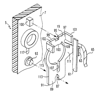
The support plate 19 of the present invention has a key-shaped opening
87 in a lobe 89 formed along a transverse edge 91 and engages a key-shaped pin
93
molded into the planar wall 11 of housing base 5. A rectangular opening 95 is
spaced
opposite from key-shaped opening 87 in lobe 97 and is formed along a
transverse edge
99 and engages a rectangular shaped pin 100 also molded into the planar wall
11 of
housing base 5. Openings 87 and 95 fit snugly over pins 93 and 100,
respectively, to
firmly fix the position of support plate 19 within housing base 5. Bent over
tabs 101
and 102 in upper lobe 97 of support plate 19 butt against the cover 7 of
housing 3 to
further maintain the fixed position of support plate 19 when the circuit
breaker 1 is
assembled.
Both pins 93 and 100 are formed in planar wall 11 of housing base 5
such that when support plate 19 is fixed thereto, pins 93 and 100 extend
beyond
support plate 19 to space cradle 49 away from support plate 19 when breaker
assembly
17 is assembled in base 5 so that cradle 49, which generally is made of a
metal
material, is spaced away from support plate 19 which, preferably, is made of a
metal
material such as steel. As is apparent, this spacing of metal support plate 19
and metal
cradle 49 is necessary in order to eliminate current travelling through plate
19 to cradle
49 and tension spring 55, thereby bypassing bimetal member 61.
A large aperture 103 approximately centrally located in support plate 19
accommodates an annular flange 105, shown in Figures 2 and 3, which is molded
on
planar wall 11 of base 5 through which a cam may extend when the circuit
breaker 1
is coupled with a similar circuit breaker to form a two-pole breaker in which
simultaneous tripping of both poles is affected by the cam extending through
flange
105. For a two pole operation, the portion of planar wall 11 aligned with
flange 105
is knocked out to accommodate the cam, in a manner well-known in the art.
21~64~8~
- 10 - 94-PDC-281
Aperture 103 and an intersecting slot 107 extend longitudinally and
centrally through support plate 19 from lobe 97 to lobe 89 as shown in Figure
3. As
is apparent, this spacing of metal support plate 19 and metal cradle 49 is
necessary as
to eliminate the possibility of current travelling through plate 19 to cradle
49 and
tension spring 55 thereby bypassing bimetal member 61. A notch 109 in the
peripheral
edge of aperture 103 helps weaken the connection of the free end 111 from the
remainder of support plate 19. Tab 63 to which bimetal 61 is secured extends
laterally
from the free end portion 111 of support plate 19 as shown in Figures 3 and 4.
Opposite to free end 111 of support plate 19 and running generally
parallel to aperture 103 and intersecting slot 107 is a longitudinal edge 113
having
portions which aid to form lobes 89 and 97 and an arcuate portion 115 adjacent
to
aperture 103 of support plate 19.
As shown particularly in Figure 2, longitudinal edge 113 of support plate
19 near lower lobe 89 terminates toward the latch ledge 53 of cradle 49 when
both
support plate 19 and cradle 49 are assembled in cavity 15 of base 5.
Referring again to Figures 3 and 4, rectangular opening 95 is slightly
wider than the width of rectangular pin 100 so that the free end 111 of plate
19 can
freely be bent during the calibration process. Whereas, opening 87 is slightly
smaller
than pin 93 for a press fit.
The calibration process for the circuit breaker 1 of Figures 1 and 2 may
be similar to that disclosed in the aforementioned U.S. Patent No. 5,008,645
and may
be performed prior to cover 7 being placed over base 5 to enclose cavity 15,
or after
cover 7 has been placed over base 5 to enclose cavity 15. If cover 7 has
already been
placed over base 5 to enclose cavity 15, an opening 117 shown only in Figure 1
may
be provided in the planar wall 11 of housing base 5 in alignment with slot 107
in
support plate 19.
A tool 110 shown in Figure 4 is inserted through opening 117 into slot
107, and is rotated to distort the free end 111 of the support plate 19
thereby rotating
tab 63 carrying the bimetal 61 and forcing the breaker to trip. As shown in
Figure 4,
the distortion causes bimetal 61 to rotate from the phantom position to the
full line
position. This calibration is performed automatically by a machine which
applies
current to the terminals, inserts the tool into opening 117 and slot 107, and
rotates the
tool to force the breaker to trip upon expiration of the prescribed time.
~1~4~8'~~
- 11 - 94-PDC-281
If cover 7 has not been placed over base 5 to enclose cavity 15, then the
machine inserts the tool into slot 107 of support plate 19 and rotates the
tool to force
the breaker to trip. Once the cover 7 is placed over base 5 and is secured in
place by
rivets 9, the circuit breaker is tested by again applying the calibrating
current and
observing whether the breaker trips at the prescribed time within specified
tolerances
in a manner similar to that described in the aforementioned U.S. Patent No.
5,008,645.
In referring to Figure 1, manual calibration can be done by inserting a hook
through
opening 119 of Figure 1 to engage the free end of the bimetal and either push
or pull
the bimetal in an attempt to bring the thermal trip within calibration limits
and/or a
tamper indicating seal 121 may be installed over opening 117 to provide a
visual
indication of any attempt to change the calibration setting as taught in the
aforesaid
U.S. Patent No. 5,008,645.
From the above, it can be appreciated that the present invention provides
a support plate which needs to extend only partially along the planar wall 11
of housing
base 5 for calibration purposes, whereas the support plate of the prior art
needs to
extend fully along the planar wall of the housing so that the plate is fixedly
secured for
calibration purposes for the circuit breaker.
While specific embodiments of the invention have been described in
detail, it will be appreciated by those skilled in the art that various
modifications and
alternatives to those details could be developed in light of the overall
teachings of the
disclosure. Accordingly, the particular arrangements disclosed are meant to be
illustrative only and not limiting as to the scope of the invention which is
to be given
the full breadth of the appended claims and any and all equivalents thereof.