Note: Descriptions are shown in the official language in which they were submitted.
2164718
WO 94/29075 PCT/US94/06816
Apparatus For Repairing Cracks
Technical Field
The following invention relates to methods and devices for repairing cracks
in materials. More specifically, the present invention relates to methods and
5 devices for crack repair in casted parts by drilling holes in the crack, threading the
holes and screwing threaded pins into the holes, especially pins having threads
which extend outward away from a central axis of the pin and upward, toward a
head of the pin.
Background Art
l 0 Materials often exhibit a variety of different failure mechanisms. Onoccasion, materials are loaded beyond a tensile strength of the material and thematerial fractures abruptly and completely. In these circumstances the material is
usually irreparable and must be replaced. However, often materials do not fail in
an abrupt complete manner, but rather fail due to fatigue or localized stresses which
l 5 exceed design criteria, causing cracks to form in the material. Often when these
cracks initially form, the material is still functional for its desired purpose. For
instance, a reciprocating machine may receive cracks in its structural material and
yet continue to operate, albeit at perhaps a lesser efficiency. Cracks thus serve as
indicators that a material is being over stressed and yet also provides an opportunity
for remedial measures to be taken without requiring entire replacement of the
affected materials.
While crack repair methods have become well known in the art, they have
traditionally been looked upon as primarily a temporary or stopgap measure whichusually cannot be relied upon to permanently repair a crack-damaged material.
2 5 Usually "repaired" cracks are still weaker than surrounding material and thus are
subject to recracking or other failure in the same location. However, crack repair is
attractive in that it can often extend the life of the material without requiring
significant downtime for the machinery which utilizes the material. Thus, crack
repair can result in the avoidance of significant replacement costs.
3 0 Accordingly, a need exists for a method and apparatus for crack repair which
can be performed in a low-cost, timely manner and yet repair the crack to a level
which makes the material as strong as (or stronger than) it was before the crackoccurred.
Crack repair pins or "plugs" have been known in the art which are threaded
3 5 into holes drilled in the cracks to prevent cracks from continuing to propagate.
These "plugs" have also been somewhat effective in resealing materials such as cast
iron casings which require that they maintain a somewhat pressurized
environment without allowing fluids to escape therefrom.
SU8ST1TUTE SHEET (RULE 26)
WO 94/29075 PCTrUS94/0681f
216 ~7 18 -2-
In addition, locks are known in the art which can draw cracks together
somewhat and extend the life a material which is cracked.
However, neither of these solutions can effectively strengthen the material to
a level which makes it stronger than it was before the crack occurred and also
5 effectively seal up the crack to establish a pressure-withstanding seam. The device
of this invention, when used in accordance with the method of this invention,
includes pins which have threads that angle upward toward the head of the pin.
These upwardly angled threads engage with complementally formed threads in
holes drilled into the crack. When the pins are advanced into the crack, the
10 upwardly sloped threads draw opposite sides of the crack toward each other. Thus,
the crack is actually drawn closed and sealed by the pins located within the crack.
The following prior art reflects the state of the art of which applicant is aware
and is included herewith to discharge applicant's acknowledged duty to disclose
relevant prior art. It is stipulated, however, that none of these rerer~llces teach
15 singly nor render obvious when considered in any conceivable combination the
nexus of the instant invention as disclosed in greater detail hereinafter and as particularly claimed.
INVENTOR PATENT NO. ISSUE DATE
Harvey 154,864 September 8,1874
Harman 2,011,484 August 13,1935
Hays 2,121,692 June 21,1938
Kirby 2,291,162 July 28,1942
Michaels 2,361,701 October 31,1944
Murphy 2,506,233 May 2,1950
Javor 2,649,650 August 25,1953
Diperstein 2,951,506 September 6,1960
Diperstein 2,998,645 September 5,1961
Forsythe 3,066,400 December 4,1962
Dalke, et al 3,660,233 May 2,1972
3 0 Diperstein 4,599,781 July 15,1986
Reed 4,662,806 May 5,1987
7~ 4,824,279 April 25,1989
Reed 4,845,828 July 11, 1989
Giannuzzi 4,892,429 January 9,1990
3 5 FOREIGN PATENT DOCUMENTS
DOCUMENT SUB- FILING
NUMBER DATE NAME CLASS CLASS* DATE
AT 154,074 11/1953 Metalock of Australia Pty., Ltd. 71.6 05/1952
GB 350,141 06/1931 Arenz 411 411 04/1930
4 0 IT 456,431 04/1950 411 411
SIJBSTITU~E SHEET (RULE 26)
~VO 94/29075 21 6 4 71 8 PCT/US94/06816
_ --3--
Various devices are known in the art which include threads which extend
upwardly. However, none of these threaded devices are configured to include all of
the features of the pins of this invention. Furthermore, none of the threaded
devices having upwardly sloping threads have been utilized in conjunction with a5 method for sealing cracks within a material.
Disclosure of Invention
In a preferred form, the pin of this invention includes a head with a means
to apply torque thereto, a neck below the head, a shoulder below the neck and a
threaded shaft below the shoulder. The head can include any of a variety of torque
10 receiving configurations. For instance, the head can have multiple facets
dimensioned to be addressed by facets of a wrench, slots formed complemental to
slots of a screw driver, or other similar structure. The head thus receives torque
and causes the pin to rotate about a central, long axis thereof.
The neck is interposed between the head and the shoulder and defines an
15 area of the pin having a weakest tensile strength when experiencing torsional loads.
Thus, when torque is applied through the head at greater and greater magnitudes,the pin fractures at the neck before fracturing in any other location.
The shoulder is interposed between the neck and the threaded shaft and
defines a greater diameter portion. As the pin is threaded into a complementally2 0 formed hole, the shoulder abuts against an outer surface of the hole, identifying a
point at which the pin can translate no`~further along the central, long axis.
The threaded shaft is a substantially cylindrical construct having a top
adjacent the shoulder and a bottom defining a surface of the pin opposite the head.
The threaded shaft has threads circumscribing an outer periphery thereof. The
25 threads include a crest defining a major dianleter thereof and a root defining a
minor diameter thereof. An upper surface extends from a bottom edge of the root
to an upper edge of the crest. A lower surface extends from a top edge of the root to
a lower edge of the crest.
The upper surface extends upward linearly from the bottom edge of the root
3 0 to the upper edge of the crest. Similarly, the lower edge extends linearly upward
from the top edge of the root to the lower edge of the crest. Thus, the upper edge of
the crest is closer to the head than the adjacent bottom edge of the root.
In mending a crack, holes are drilled such that a central axis of the hole
extends between opposite sides of the crack. Each hole is configured such that the
3 5 diameter and the threads thereof are substantially complemental to the threaded
shaft of the pins. However, a major diameter of the hole is slightly greater than a
major diameter of the pin. A pin is threaded into the hole by applying torque
through the head until the shoulder abuts the surface of the material. At that point,
the pin can no longer translate along the central axis and into the material.
SUBSTITUTE SHEET (RUI E 26)
2t6i718;
'CT,"JS ~ 4 / 06 8 16
~4~ ~6~ec~PCTJPT013JANl995
Further torque is applied to the head causing the pin to rotate and causing the
upper surface of the threads to slide along the complementally formed threads ofthe hole drawing opposite sides of the hole toward each other and hence oppositesides of the crack toward each other. The application of torque is continued until a
maximum torsional force for the neck is reached causing the head to shear off at the
neck.
Multiple threaded holes are located along the length of the crack and filled
with pins to mend the crack. In addition, locks may first be placed transverse to the
crack which fit within complementally formed lock receiving holes having a
slightly greater length than the locks. Thus, when the locks are placed within the
lock receiving holes, the crack is drawn closed somewhat.
Brief Description of Dl.lw;.~
Figure 1 is an elevational view of a pin of this invention screwed into a hole
in the material being mended, the hole shown in section.
l S Figure 2 is a elevational view of the pin of figure 1 before threading into the
hole of figure 1.
Figure 3 is a partial section detail view of the pin of figure 2 taken along theline 3 - 3 of figure 2.
- Figure 4 is a sectional view of the hole shown in figure 1.2 0 Figure 5 is elevational view of a taping bit configured to form the threads
shown in the hole of figure 4.
Figure 6 is a detail of a portion of the teeth shown in figure 5.
Figure 7 is bottom view of that which is shown in figure 5.
Figures 8 through 11 reveal steps in the crack repair method of this invention
showing the sequence of pin application preferred for mending a crack in a
material.
Figure 12 reveals an alternative crack mending arrangement including locks.
Figure 13 is a flow chart revealing the steps involved in the method of crack
repair of this invention.
3 0 Figure 14 is an elevational view of an alternative embodiment of that which
is shown in figure 2 with some features shown in section and some hidden features
revealed.
Figure 15 is an elevational view of an alternative embodiment of that which
is shown in figure 14 with some hidden features revealed.
3 S Figure 16 is an elevational view of an alternative embodiment of that which
is shown in figure 14 with some hidden features revealed.
Figure 17 is a sectional view of an alternative embodiment of that which is
shown in figure 2 in place within a hole which is an alternative embodiment of the
hole shown in figure 4.
~ME~DED SHEE~
8 PCT/US c 4 / o 6 8 1 6
~5~$~ ?~ P~T~TG13JANl995
Figure 18 is a schematic view of the pin of figure 17 revealing how the pin of
figure 17 would mend a crack in a corner of a material.
Figure 19 is an elevational view of a series of pins, representing an
alternative embodirnent of this invention, within a hole shown in section.
Figure 20 is a front view of an alternative embodiment of the pin of this
invention.
Figure 21 is a sectional view of an alternative embodiment of the hole shown
in figure 1.
Figure 22 is an isometric view of the pin of figure 20 entering the hole of
1 0 figure 21.
Figure 23 is an isometric view of that which is shown in figure 22 with the
pin seated within the hole.
Figure 24 is an isometric view of that which is shown in figure 23 with a
portion of a head of the pin ground flush with the surface.
I S Figure 25 is an isometric view of a bit utilized to form the hole of figure 21
with the hole shown in section.
Figure 26 is an alternative embodiment of the bit shown in figure 25.
Figures 27 through 29 are perspective views revealing successive steps in
- utilizing an alternative cusped pin within a hole formed by the bit shown in figure
26.
Figure 30 is an isometric view of a roughing tap utilized in forming the hole
of figure 21.
Figure 31 is an isometric view of a finishing tap utilized after the roughing
tap of figure 30 in forming threads within the hole of figure 21.
2 S Figure 32 is an isometric view of a bottoming tap utilized after the finishing
tap of figure 31 in forming the threads within the hole of figure 21.
Best Mode(s) For Carrying Out The Invention
Referring to the drawings wherein like referellce numerals represent like
parts throughout, reference numeral 10 (figure 1) is directed to a pin for repairing a
3 0 crack C in a material M. The pin 10 is threaded into a hole H drilled into the crack C
and utilizes upwardly directed threads 60 to draw opposite sides of the crack C
toward each other, thus strengthening and sealing the material M surrounding thecrack C.
In essence, and referli,.g to figures 1 through 4, the pin 10 includes a head 203 5 at an uppermost portion thereof, a neck 30 below the head 20, a shoulder 40 below
the neck 30 and a threaded shaft 50 extending below the shoulder 40. The threaded
shaft 50 includes threads 60 thereon which include an upper surface 66 and a lower
surface 68 (figure 3) which extend upward toward the head 20 from a minor
diameter 64 to a major diameter 62. Thus, a crest 70 of each thread 60 is closer to the
216471~
PCTIUS 9 4 / 06 8 16
4~ Ti-7 1 3 J A N l995
head 20 than a portion of the thread 60 between adjacent roots 80 at the minor
diameter 64.
The hoLe H (figure 4) is drilled into the material through a plane which is
coincident with an exposed portion of the crack C. The hole H is threaded with
threads T by a tapping bit 550 (figures 5 through 7) which causes the threads T to be
substantially complemental to the threads 60 of the pin 10. The threads T of thehole H thus are closer to a surface S of the material M at a major diameter A of the
threads T than at a minor diameter B of the threads T.
The head 20 is coupleable to a torque applying instrument which can thread
1 0 the pin 10 into the hole H. The shoulder 40 has a greater diameter portion 42 which
has a diameter greater than a diameter of the threaded shaft 50. When the threaded
shaft 50 has been screwed entirely into the hole H, the greater diameter 42 of the
shoulder 40 abuts against the surface S of the material M. This abutment prevents
the pin 10 from translating along a central long axis 2 any deeper into the hole H.
1 S Upon further rotating of the pin 10, the upper surface 66 of the threads 60
engage the threads T of the hole H forcing a first curved wall G of the hole H on one
first side D of the crack C toward a second curved wall I of the hole H on a second
side E of the crack C. The first side D and the second side E of the crack C are thus
- drawn toward each other.
2 0 The neck 30 includes a necked down crease 32 which fractures, shearing the
head 20 off of the pin 10 when a magnitude of torque applied to the pin 10 reaches a
maximum torque to be applied to the threads 60. Thus, the neck 30 prevents the
threads 60 from being overly stressed torsionally.
More spe~ifi~ ~lly~ and refer~ing in detail to figures 1 through 4, the pin 10 and
2 S associated hole H are shown in detail. The pin 10 includes the head 20 at an
uppermost end thereof. The head 20 preferably includes multiple facets 22 arranged
to allow a torque applying device to effectively engage the head 20. Preferably, the
facets 22 are arranged in a hexagonal pattern to be engaged by a variety of commonly
available torque applying tools. Alternatively, various other facet arrangements3 0 could be utilized or slots such as those receiving a screw driver or other tool could
also be used. The head 20 is preferably radially symmetrical about a central axis 2
passing through the pin 10.
The neck 30 joins the head 20 to the shoulder 40. The neck 30 is preferably
arranged as a single frustum with a greater diameter base 34 adjacent the head 20
3 S and a lesser diameter crease 32 adjacent the shoulder 40. The crease 32 and base 34
thus define parallel planes of the frustum of the neck 30. The crease 32 is preferably
designed to have a cross-sectional area which is less than a cross-sectional area of
any other portion of the pin 10. Thus, when torsional loads increase, the pin 10 is
most likely to fracture at the crease 32 than at any other location along the pin 10.
C~nrn ~ ._._
216 1718
~C~IUS94/068 16
~7~ ~6R~ PCT/PTG 13JAN1995
In addition, the crease 32 is preferably provided with a cross-sectional area
which gives the crease 32 a maximum torsional load characteristic which is less
than a torsional load necessary to cause damage to the threads 60 of the threaded
shaft 50. In this way, if torsional loads on the pin 10 begin to approach a level which
S could cause damage to the threads 60 of the threaded shaft 50, the crease 32 of the
neck 30 will fracture before a thread 60 damaging load is reached.
The shoulder 40 includes a greater diameter portion 42 directly adjacent the
crease 32 of the neck 30. The greater diameter 42 of the shoulder 40 preferably has a
greater diameter than a major diameter 62 of the threads 60. The greater diameter
1 0 42 also preferably has a greater diameter than a major diameter A of the hole H.
The greater diameter 42 transitions to a lesser diameter 44 of the shoulder 40
directly adjacent a top 52 of the threaded shaft 50. A frustum 46 is formed between
the greater diameter 42 of the shoulder 40 and the lesser diameter 44 of the shoulder
40. This frustum 46 is somewhat irregular adjacent the lesser diameter 44 in that it
1 5 transitions into the top 52 of the threaded shaft 50 where the helically wound
threads 60 terminate. The shoulder 40 abuts against the surface S of the material M
surrounding the hole H when the pin 10 is threaded into the hole H a sufficient
distance along the central axis 2. The shoulder 40 prevents the pin 10 from
translating into the hole H beyond a finite amount. The shoulder 40 thus causes
2 0 the threads 60 of the pin 10 to draw the first side D and second side E of the crack C
toward each other, rather than the thread 60 drawing the pin 10 further into thehole H along the central axis 2. The shoulder 40 thus acts to redirect forces applied
~setween the pin 10 and the hole H.
The threaded shaft 50 is a substantially cylindrical construct which extends
2 S from the lesser diameter 44 of the shoulder 40 at a top 52 thereof to a bottom 54
which defines an opposite end of the pin 10 from the head 20. The threaded shaft 50
is oriented about the central axis 2 with the central axis 2 passing through a
geometric center of the threaded shaft 50. The threaded shaft 50 has threads 60
formed about the cylindrical surface thereof.
3 0 The threads 60 are actually one continuous helically wound thread which
begins at the bottom 54 and spirals up to the top 52. While this single thread design
is plefe,~ed, other arrangements including compound series of threads which windhelically together from the bottom 54 to the top 52 could also be utilized.
The threads 60 include a crest 70 defining a major diameter 62 of the threads
3 S and a root 80 defining a minor diameter 64 of the threads 60. As shown in detail in
figure 3, the threads 60 have an upper surface 66 which extends from a bottom edge
84 of the root 80 to the upper edge 72 of crest 70. The threads 60 also include a lower
surface 68 which extends from a top edge 82 of the root 80 to a lower edge 74 of the
crest 70. Both the upper surface 66 and lower surface 68 angle upwards toward the
~M~D Sl~
216~718
iCTiUS94/d68 16
-8- ~6 Recd PCTIPTO 13 JANl~5
head 70 as the surfaces 66, 68 extend from the root 80 to the crest 70. Both the crest
70 and root 80 exhibit a constant distance from the central axis 2 between the upper
edge 72 and lower edge 74 and between the top edge 82 and the bottom edge 84.
In section, the surfaces 66, 68 extend linearly from the root 80 to the crest 70.
S However, as this contour is rotated helically about the threaded shaft 50 along with
the threads 60, the upper surface 66 and lower surface 68 take on a curved surface
appearance. This appearance is similar to that which would be formed by a linearsection of the surface of a cone with a tip of the cone oriented downward and the
cone rotated and translated upward along a central axis thereof. The upper surface
1 0 66 and lower surface 68 thus have a curved surface in three dimensions similar to
that of a cone, but a linear character when viewed in section.
The upper surface 66 extends from the root 80 to the crest 70 at an upper
surface angle a diverging from a reference plane 4 orthogonal to the central axis 2.
The upper surface angle a is preferably 20 but could be any angle between 0 and
1 S 90. The lower surface 68 extends from the root 80 to the crest 70 at a lower surface
angle ~ with respect to the ~efeLence plane 4. The lower surface angle ,B is preferably
40 but could vary between 0 and 90.
The upper surface angle a is preferably less than the lower surface angle ~
such that a thickness of the threads 60 at the crest 70 is less than a thickness of the
2 0 threads 60 between adjacent roots 80. In this way, the threads 60 are provided with
greater thickness, and hence greater strength adjacent the minor diameter 64 than at
~he major diameter 62 and are thus more capable of bearing the loads experiencedwit~-lin the hole H.
R ferring now to figure 4, details of the hole H are shown. The hole H is
2 S preferably substantially complemental in form to the threaded shaft 50 of the pin 10.
The hole H includes threads T which include a major diameter A and a minor
diameter B. Each thread T includes a lower surface L and an upper surface U. Thehole H includes a ffrst curved wall G on the first side D of the crack C and a second
curved wall I on the second side E of the crack C. The hole H is thus bisected by the
3 0 crack C.
The hole H is preferably located so that the crack C divides the hole H into
two substantially equal portions. Thus, the hole H is oriented to extend along a line
which approximates the direction of orientation of the crack C with respect to the
surface S. Preferably, the hole H extends to the crack C from the surface S down to a
3 S location where the crack C stops. However, the hole H can stop short of a full depth
of the crack C (as shown in figures 1 and 4) when pins 10 of sufficient length are not
available or when a hole H of shorter depth is sufficient to receive a pin 10 that can
effectively support all of the crack C.
~0 S~E~
216~718
-9- -~&F e~d9P4 / ~6~ r ~
The threads T of the hole H are shaped to have surfaces L,U which conform
to the upper surface 66 and lower surface 68 of the threads 60 of the pin 10.
However, a major diameter A of the hole H is ~refelably slightly greater than a
major diameter 62 of the threads 60 and the minor diameter B of the threads T isS preferably slightly greater than a minor diameter 64 of threads 60.
This slight disparity provides a tolerance between the pin 10 and hole H for
ease of fitting of the pin 10 into the hole H. Furthermore, this provides a finite
amount of travel between the first curved wall G and the second curved wall I ofthe hole H when the pin 10 is tightened into the hole H, causing the first side D and
1 0 second side E of the crack C to be drawn toward each other. Thus, the major
diameter A and minor diameter B of the hole H are initially greater than the major
diameter 62 and minor diameter 64 of the threads 60. After tightening the pin 10into the hole Hj this difference between the hole H and the threaded shaft 60 isreduced or eliminated.
1 S Figures 5 through 7 show details of the tapping bit 550 ~re~elably used to form
the hole H. The tapping bit 550 is ~refelably a substantially cylindrical construct
having a torque input head 590 at one end thereof and a bottom 552 on an opposite
end thereof. A stop 580 defines a transitional region between a lesser diameter 582
and a greater diameter 584 portion of the tapping bit 550. The stop 580 is located a
2 0 distance from the bottom 552 equal to a desired depth of the hole H to be formed by
the tapping bit 550. The lesser diameter 582 of the tapping bit 550, below the stop
580, is preferably sl~bstantially similar to a diameter of the hole H before threading
thereof Wi~;l th~ ~hl~eads T.
A plurali~y of teeth 560 are oriented proximate to the bottom 552 which
2 S extend helically around the tapping bit 550 at an angle similar to an angle of the
threads T within the hole H. The teeth 560 include an upper side 562, a lower side
564, an outer side 566 and an inner side 568. Each of the teeth 560 is interrupted by a
cutout groove 575 which prevents the teeth 560 from forming one continuous toothextending along the tapping bit 550. The cutout groove 575 allows filings cut out of
3 0 the hole H by the tapping bit 550 to escape from the teeth 560 and allow the teeth 560
to cut the threads T into the hole H without obstruction.
The teeth 560 are shaped with an upper side 582, lower side 564, outer side
586, and inner side 568. These sides 562, 564, 566, 568 are dimensioned in a manner
similar to the threads T of the hole H. As noted above, the threads 60 of the pin 10
3 S are slightly smaller in major diameter 62 and minor diameter 64 than the threads T
of the hole H and thus, the teeth 560 are slightly larger in dimension than surfaces
66, 68 of the pin 10.
The upper sides 562 of each of the teeth 560 are oriented at an angle from a
reference plane 554 orthogonal to a long axis of the tapping bit 550 at upper side
AMENOEO ~m
21 6~ 7I 8
o PCTIUS94/~OT6~.6 1995
angle p. The lower side 564 is angled at a lower side angle ~ with respect to the
reference plane 554. The lower side angle ~ and upper side angle p are preferably
similar to the lower surface angle ~ and upper surface angle a respectively.
A portion of the teeth 560 directly adjacent to the bottom 552 are beveled at a
S bevel 570 having a bevel angle y of preferably 60. This bevel 570 allows the teeth
560 to cut the thread T into the hole H in progressively greater amounts as the
tapping bit 550 initially enters the hole H. While the tapping bit 550 is preferably
utilized to from the threads T within the hole H, other bits and other methods of
forming threads may be utilized to form the threads T within the hole H.
1 0 In forming the threads T within the hole H, the tapping bit 550 is oriented
overlying hole H and is coupled to an ayyroyriate torque applying device, such as a
drill. The bit 550 is then lowered into the hole H with the bottom 552 ente,ing the
hole H. As the tapping bit 550 is lowered into the hole H the threads T are cut into
the first curved wall G and the second curved wall I of the hole H.
1 5 In use and operation and re~ ,g to figures 8 through 12 and figure 13, the
pin 10 is preferably utilized in conjunction with other similar pins 10 in the
following manner to mend a crack C within a material M. Initially, a user identifies
the location and extent of the crack C. The crack C includes ends N defining an
extent of the crack C along the surface S. Once the crack C has been fully identified,
2 0 locks 100 may be optionally placed transverse to the crack C such as those disclosed
in detail in U.S. Patent Number 4,662,806 (see figure 12). These locks 100 act to draw
opposite sides of the c ac~ oward each other and to prevent the crack C from
widening during the r.l i, dirlg process. Each lock 100 is driven into a
complementally formed, but slightly longer, lock receiving hole 101
2 S Holes H are then drilled into the crack C along the length of the crack. The
holes H preferably extend slightly beyond a visible extent of the crack C at each end
of the crack C. This ensures that the entire crack C is included in the mending
process. The holes H are spaced a distance apart slightly less than a diameter of each
hole H.
3 0 The holes H are then tapped with threads T so that they take on an
appearance such as that shown in figure 4. Once all of the holes H have been
threaded, the pins 10 are threaded into the holes H. Preferably, the pins 10 arethreaded into the holes H until the heads 20 thereof shear off at the neck 30. This
ensures that the pins 10 have been fully tightened into the holes H. An ayyropriate
3 S grinding tool is then used to grind down the remainder of each pin 10 to be flush
with the surface S.
While the crack mending procedure could be complete at this point,
preferably holes are drilled into the crack C in between where pins 10 have already
~AENDED SH~
-
2l6~7l8
U~94/068:6
-11- 46Re~'dPCTlPTCI3J~1995
been placed (note that this can require that portions of pins 10 may need to be
drilled out). Rather than drill holes H into every space between the pins 10 that
have already been located into the crack C, holes H are drilled at every other gap
between already located pins 10. Once these holes H are fitted with pins 10,
5 remaining gaps between filled holes H are drilled to make holes H with pins 10 that
are threaded thereinto.
Drilling of the holes H thus occurs in three stags. A first stage drills holes Hat each end N of the crack C and every other hole H location that will eventually be
drilled. A second stage drills holes H at any other gap along the crack C between
10 adjacent holes H of the first stage. A third stage drills holes H at every remaining
gap along the crack C between adjacent holes H.
Once the final portions of the crack C have been provided with holes H, all of
the crack C visible upon the surface S will have been drilled out and incorporated
into a portion of a hole H and threaded with a pin 10. However, at no time during
15 the mending process will two holes H have been formed and not filled with pins 10
that are adjacent to each other and overlap each other.
In this way, each pin 10 fitted within the holes H is maintained with at least
three-quarters of a circumference thereof in active engagement with the material M,
insuring that the threads 60 of the pins 10 will not separate from the threads T of
2 0 the hole H within the material M. The pins 10 are then ground down to be flush
with the surface S leaving a surface S with no visible cracks C and only revealing a
region where a series of pins 10 ~rLd, optionally locks 100 have been imbedded into
the material M. i - ~ ~
Referring again to figure 1, details of the exact mechanism of crack C closure
2 5 are described. As the pin 10 is threaded into the hole H, rotation of the pin 10 causes
a force F to be exerted between the threads 60 and the threads T of the hole H. This
rotational force F is counteracted through the threads 60, T, causing the pin 10 to
migrate downward into the hole H. When the pin 10 has entered the hole H a
s11fficient distance to cause the shoulder 40 to abut the surface S surrounding the
3 0 hole H, this vertical downward response of the pin 10 to the rotational force F is
halted.
However, continued force F applied rotationally to the pin 10 continues to
cause the upper surface 66 of the threads 60 to engage the upper surface U of the
threads T of the hole H. This continued force F, rather than drawing the pin 10
3 5 downward vertically along the central axis 2, exerts a force F' against the material M
on each side of the hoie H tending to draw the first curved wall G and the second
curved wall I toward each other. This closing force F' causes the first side D and
second side E of the crack C to be drawn toward each other. In this way, the pins 10
Al\~ENDED S~IEET
216il7I8
-12- 46 Rec~d PCT/P;G ~q3 J A N 1995
and also the pins 110, 210, 310, 410, 910, 1010 draw the first side D and second side E
of the crack C toward each other, thus mending the crack C.
Referring now to figure 14, an alternative embodiment of the pin 10 is
shown. Pin 110 is similar in form to the pin 10 except that the shoulder 140 of the
pin 110 does not include a frustum 46 (see figure 2) but rather includes a cusp 144.
The cusp 144 is formed by a greater diameter portion 142 and a lesser diameter
portion 146, with the lesser diameter portion 146 adjacent the threaded shaft 150 yet
closer to the head 120 than the greater diameter portion 142. This pin 110, whenscrewed into the hole H has the cusp 144 address the surface S surrounding the hole
1 0 H and preferably impregnates the surface S somewhat. Thus, the shoulder 140 fits
tightly into the surface S surrounding the hole H before the head 120 snaps off at the
neck 130.
Referring now to figure 15, an alternative embodiment of the pin 10 is
shown. This pin 210 includes a head 220 with facets 222 thereon above a neck 2301 5 which extends to a shoulder 240 which in turn is connected to a threaded shaft 250.
The pin 210 differs from the pin 10 in that the shoulder 240 has a greater diameter
242 and a lesser diameter 244 which bound opposite sides of a frustum 246 which
diverges very gradually between the lesser diameter 244 and the greater diameter- 242.
2 0 Figure 16 reveals an alternative embodiment of the pin 10. The pin 310
differs from the pin 10 of the preferred embodiment in that the shoulder 340
diverges more quickly between a lesser dia~leter 3~4 and a greater diameter 342. A
head 320 with facets 322, neck 330 and th~ e~ sha~t 350 are substantially similar to
the pin 10.
2 5 Figure 17 reveals an alternative embodiment of the pin 10. Pin 410 includes a
head 420 with facets 422 similar to that exhibited by the pin 10. A neck 430 of the pin
410 is also similar to the neck 30 of the pin 10. A shoulder 440 of the pin 410 is
optional, but shown in figure 17 in a form similar to a shoulder 340 exhibited by the
pin 310. However, the threaded shaft 450 of the pin 410 is distinct from the threaded
3 0 shaft 50 of the pin 10 in that the minor diameter 464 of the pin 410 is not constant,
but rather decreases as it moves away from the head 420.
The minor diameter 464 thus diverges at an angle ~L divergent from a parallel
orientation as is exhibited by the pin 10. This diverging minor diameter 464 is
mirrored by the major diameter 462 of the pin 410. In use and operation, the pin3 5 410 is screwed into a hole H' having a complementally formed diverging majordiameter A' and minor diameter B' within threads T'. Eventually the pin 410
reaches a point at which threads 460 abut against the threads T' in the hole H'.This abutment prevents the pin 410 from further translation downward
along central axis 402. Thus, further rotation of the pin 410 causes the first side D
~AENO~D St~E~T
21 G~ 718
,, , ~
PCT,'~S 94/ 06 8 16
-13- 48 ,~'d PCT~P~G 13 J A N l995
and second side E of the crack C, upon which the hole H is located, to be drawn
together. The neck 430 snaps the head 420 off when a sufficient torque is applied to
the head 420, through the facets 422, to ensure that the threads 460 have effectively
engage the threads T' of the hole H'.
S Figure 18 reveals a comered portion of the material M with a crack C therein.
Figure 18 schematically represents a possible orientation of the pin 410 which would
draw a first side D and second side E of the crack C toward each other, thus repairing
the crack C. This utilization of the pin 410 allows opposite sides of the crack C to be
drawn together when no convenient flat surface S is provided for abutment with
1 0 the shoulder 440.
Referring now to figure 19, an alternative embodiment of pin 10 is shown.
The pin 610 is particularly designed for use in holes H" that are especially long,
because a long crack C has formed in a thick material M. The pin 610 is similar to
the pin 10 except that the pin 610 does not have a head, neck, or shoulder. Instead,
1 S the pin 610 has a top 652 with a torque tool receiver 620 therein. The pin 610 is
screwed into the hole H" with the threads 660 engaging the threads T until the
bottom 654 abuts against a bottom wall J of the hole H". This abutment prevents
further translation of the pin 610 into the hole H". Further rotation of the pin 610
- causes the threads 660 to draw the threads T and associated crack sides D, E toward
2 0 each other.
A second pin 610 can then be screwed into the hole H" directly over the first
pin 610. The second pin 610 will continue into the h~le H" until its bottom 654
abuts with the top 652 of the first pin 610. This ab~ n~ ws the second pin 610
to draw sides D, E of the crack C together. In this way, long cracks C can be securely
2 S mended.
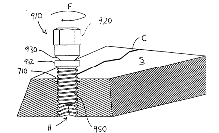
Referring now to figure 20, an alternative embodiment of the pin 10 is
shown. The pin 910 includes a head 920 and neck 930 similar to the head 20 and the
neck 30 of the pin 10 (figure 1). The pin 910 also includes a threaded shaft 950 with
threads 960 similar to the threaded shaft 50 and threads 60 of the pin 10. The pin 910
3 0 differs from the pin 10 in that a shoulder 912 is provided differing from the
shoulder 40 of the pin 10. The shoulder 912 preferably includes a side wall 914 of
substantially cylindrical construction and a bottom wall 916 which is preferablysubstantially perpendicular to the side wall 914 and to a long axis of the pin 910.
An angle ~ between the bottom wall 916 and the side wall 914 is preferably
3 S 90. However, the angle ~ can be increased so that the bottom wall 916 exhibits a
cusp-like appearance similar to that shown in figure 14. The bottom wall 916 canabut against the surface S, but preferably abuts against a floor 714 (figure 21) within a
counterbore 710 surrounding the hole H adjacent the surface S.
AMENDED SHEET
2I 6~ 71
~CTIU~94/~6 8 16
-14- 46 Re~'d PCTIPTC 1 3 JA N l995
The shoulder 912 connects to the threaded shaft 950 through a frustum 918.
The frustum 918 provides clearance between the shoulder 912 and an uppermost
end of the threaded shaft 950, which allows the threads 960 to be formed with the
upwardly sloping surfaces characterized in detail hereinabove with respect to the
5 pin 10. The frustum 918 preferably has an exterior surface which angles at a slope
of preferably 30 away from the sidewall 914 of the shoulder 912.
Figure 21 reveals a modified form of the hole H which particularly facilitates
secure attachment of the pin 910 therein and secure binding of opposite sides of the
crack C. Particularly, the hole H includes a counterbore 710 formed at a transition
1 0 between the hole H and the surface S. The counterbore 710 ~rererably includes a
cylindrical side surface 712 dimensioned similarly to the side wall 914 of the pin 910.
The side surface 912 extends from the surface S down to the floor 714. The floor 714
is preferably angled at an angle 0 of approximately 90 away from a central axis of
the hole H.
l 5 Alternatively, the angle ~ can be greater than 90 and conform to any angle
exhibited by the angle ~ of the bottom wall 916 of the pin 910. Examples of this angle
H greater than 90 are exhibited in the shoulder 140 of the pin 110 (figure 14) and the
bottom wall 1016 of the pin 1010 (figures 27 through 29) discussed further
hereinbelow. The floor 714 extends from a lower edge of the side surface 912 into a
2 0 thread relief 718 which extends down from the floor 714 to the threads T along a
slope ~ preferably of approximately 30 from the central axis of the hole H.
The counterbore 710 allows the shoulder 912 to rest below the surface S
partially so that when portions of the shoulder 912 are grolwnd-1~.r~y to a level
coplanar with the surface S, a portion of the shoulder 912 rem~ins ~lad allows the
2 5 pin 910 to continue to maintain an opposing force between the shoulder 912 and the
threads 960 equally on opposite sides of the crack C at floor 714 to hold opposite
sides of the crack C together. When the surface S is sloped or curved, the
counterbore 710 provides a surface against which the shoulder 912 can still securely
contact. Also, when a material is severely cracked so that the opposite sides of the
3 0 crack C are not held together, the counterbore 710 ~f~vents one side of the crack C
from being elevated upwards which would allow the threads T, 960 to disengage
and the joint to separate.
When the crack C passes through the material at an angle non-perpendicular
to the surface S, the hole H may be formed within the plane of the crack and non-
35 perpendicular to the surface S with the floor 71~ of the counterbore 710perpendicular to the hole H and non-parallel with the surface S. In this way, the
shoulder 912 of the pin 910 can still securely rest within the counterbore 710
without having the shoulder 912 abut one side of the crack C before the oppositeside of crack C. The shoulder 912 of the pin 910 is prererdbly of sufficient height that
~D ~HEET
2164718
~CTIlJS 9 4 / 06 8 16
~6 Re~d PCTIPTG 13 JANl995
a top portion of the shoulder 912 can be ground away to a plane parallel to the
surface S while still providing sufficient material within the shoulder 912 to resist
deflection of the shoulder 912 when the pin 910 is secured within the hole H.
Referring now to figures 22 through 24, details of the utilization of the pin
S 910 are shown. After the threaded hole H is formed passing within a plane
substantially coplanar with the crack C and the counterbore 710 has been formed,the pin 910 is located within the hole H by rotation about arrow F (figure 22).
Rotation continues about arrow F until the shoulder 912 abuts against the floor 714
(figure 21) of the counterbore 710. As additional rotational forces are applied about
1 0 arrow F, opposite sides of the crack C are drawn together as discussed hereinabove
with respect to utilization of pin 10. Once sufficient torque is applied that the neck
930 can no longer resist deforrnation, the head 920 is severed therefrom as shown in
figure 23. Finally, a portion of the shoulder 612 above the surface S is ground until
coplanar with the surface S and is peened to further seal the pin 910 into the hole H.
1 5 Various adhesive fluids may be utilized to further enharrce the secure locking of the
pin 910 within the hole H.
With reference now to figure 25, details of the formation of the counterbore
710 are shown. A spot facing bit 800 having a particularly formed cutting surface is
utilized to form the counterbore 710. Particularly, the spot facing bit 800 includes an
2 0 angled edge 802 having an angle which conforms to the slope I of the thread relief
18 and a floor forming edge 804 having an angle which conforms substantially with
the angle 0 of the floor 714 of the counterbore 710. A portion of the spot facir~.g bi-~
800 below the angled edge 802 is preferably not greater in diameter than a diarneter
of the hole H. Thus, when the spot facing bit 800 is lowered axially into the hole H,
2 S the angled edge 802 and floor forming edge 804 form the counterbore 710. A depth
of the counterbore 710 is preferably controlled by some form of drill stop or other jig
to prevent the counterbore 710 from passing too deeply into the hole H.
Alternatively, and shown in figure 26, a spot facing bit 810 can be used which
has a cusp-cutting edge 814 and an angled edge 812 which form a cusped floor 7163 0 within the counterbore 710. This cusped floor 716 can complement a geometry of a
cusped pin 1010 (shown in figures 27 through 29) which is similar in many ways to
the pin 110 (figure 14).
The cusped pin 1010 includes a head 1020 and neck 1030 similar to that of the
pin 910. However, the cusped pin 1010 has a shoulder 1012 with a bottom surface
3 5 1016 which exhibits an angle ~ (figure 20) greater than 90. When this cusped pin
1010 is utilized in a hole H having a counterbore 710 with a cusped floor 716, the
shoulder 1012 and floor 716 can interface and cause further amplification of thecrack closing force F' (figure 1), especially near the surface S. As shown in figures 27
,~MtN~ ~E~T
- 216~7i8
. . .
-16- 46 ~,~CT,IUpSC9T~4pTG~ ~ 3~'~N1995
through 29, the cusped pin 1010 is preferably utilized similarly to the manner of use
of the pin 910.
With refer~-ce now to figures 30 through 32, details of the threading of the
hole H are shown. As an alternative to the tapping bit 550 shown in figure 5, a
S series of taps 820, 830, 840 can be used to most effectively form the threads T within
the hole H. Initially, a roughing tap 820 is passed axially into the hole H to form a
first rough shape of the threads T. The roughing tap 820 is followed by a finishing
tap 830 which completes formation of the threads T within an open hole H. If a
hole H"' formed as a blind bore is to receive the pin 10, 110, 210, 310, 410, 610, 910, a
l 0 bottom tap 840 can be utilized to fully form the threads T to within one thread T of a
bottom of the hole H"'. By utilizing the three taps 820, 830, 840 in series, a more
precisely threaded hole H, H"' can be formed with less damage to the taps 820, 830,
840.
Moreover, having thus described the invention, it should be apparent that
l S numerous structural modifications and adaptations may be resorted to without
departing from the scope and fair meaning of the instant invention as set forth
hereinabove and as described hereinbelow by the claims.
Industrial Applicability
The industrial applicability of this invention shall be demonstrated through
2 0 discussion of the following objects of the invention.
It is a primary object of the present invention to provide a method for
mending a crack in a material by drilling holes in the material and locating
threaded pins therein with threads which angle upwards towards a surface of the
material.
2 S Another further object of the present invention is to provide a method for
mending cracks which draws opposite sides of the crack closer together.
Another -further object of the present invention is to provide a method for
mending cracks that strengthens the cracked region to an equal or greater strength
than surrounding regions.
3 0 Another further object of the present invention is to provide a method for
mending cracks which totally removes the crack from the material.
Another further object of the present invention is to provide a method for
mending cracks which can mend cracks existing in sharply angled casted materials.
Another further object of the present invention is to provide a crack
3 S mending pin that has threads which angle upwards toward a head of the pin.
Another further object of the present invention is to provide a mending pin
which has a head which is driveable by a commonly available torque applying
device.
AM~ HEE~
2l6~7l8
~CTIUS 94 / 06 8 16
46 Rec'd PCTIPTG 13 JAN l995
Another further object of the present invention is to provide a mending pin
which has threads which are slightly spaced from each other and maintain a
minimum thicl~ness between a root and a crest thereof, providing a durable thread.
Another further object of the present invention is to provide a mending pin
5 designed to enter a complementally formed hole only a finite distance and then to
have the opposing sides of the hole drawn toward each other.
Another further object of the present invention is to provide a mending pin
which has a necked-down portion which snaps off before threads of the mending
pin are damaged.
Another further object of the present invention is to provide a tap capable of
tapping holes with threads that angle upwards towards a surface of the material in
which the hole is drilled.
Another further object of the present invention is to provide a mending pin
which is simple and inexpensive to manufacture and yet durable in construction.
Another further object of the present invention is to provide a tap which
easily forms threads within a hole, the threads receiving a mending pin which has
threads which angle upward toward a head of the pin.
Another further object of the present invention is to provide a method and
- apparatus for quickly mending cracks in cast machinery without disassembly of
2 0 components of the machinery.
Another further object of the present invention is to provide a method and
apparatus for mending cast metal machinery that can be performed at the site of the
machinery with easily transportable tools.
Another further object of the present invention is to provide a mending pin
2 5 which can draw together sides of a complementally formed hole drilled into a crack
and hold the sides together after portions of the pin above a surface of the cracked
material are ground away.
Viewed from a first vantage point, it is an object of the present invention to
provide a threaded pin for location into a threaded hole that straddles a crack in a
3 0 material having a surface, the hole including a first curved wall on a first side of the
crack and a second curved wall on a second side of the crack, the hole includingthreads therein with a major diameter and a minor diameter with a portion of each
thread adjacent the major diameter closer to the surface than any other portion of
the thread, said pin comprising, in combination: a head including a means to
3 5 transfer torque to said pin, a threaded shaft extending from said head including
threads thereon, at least one of said threads including a crest defining a majordiameter of said threaded shaft, a root defining a minor diameter of said threaded
shaft, and an upper surface extending from a bottom edge of said crest, said upp er
surface having a portion thereof extending toward said crest at an angle greater than
~`~F~n e~FT
2I 64 71
-18- ~CTIUS 9 4 / 0 6 8 16
~6 Re~'d PCT/PTG 1 3 JAN l99
zero from a referel,ce plane perpendicular to said central axls, and means for
opposing central axis translation of the pin; whereby when said pin is threaded into
the hole, said central axis translation opposition means causes further rotation of
said pin to force the first side of the crack and the second side of the crack together.
Viewed from a second vantage point, it is an object of the present invention
to provide a tapping bit for forming threads in a hole in material, the threads
having a major diameter and a minor diameter, each section of the threads being
closer to a surface of the material at the major diameter than at an adjacent minor
diameter, said tapping bit comprising in combination: a cylindrical body similar in
diameter to the hole to be tapped, and teeth extending from said cylindrical body,
each tooth having a contour including an upper side, a lower side, and a outer side
and spaced vertically from adjacent teeth by an inner side, said inner side and said
outer side spaced horizontally a distance simil~r to a desired distance between the
minor diameter and the major diameter, said upper side and said lower side both
higher in elevation adjacent said outer side than adjacent said inner side; whereby
the tapping bit carves threads into the hole which extend away from a minor
diameter and toward the surface.
Viewed from a third vantage point, it is an object of the present invention to
provide a method for securing opposite sides of a crack in a material together
2 0 including the steps of: drilling a hole through a surface of the material and between
opposite side of the crack, tapping the hole with threads, the threads characterized
by having an upper surface which is closer to said surface at a major diameter of the
threads than at a minor diameter of the threads, threading a pin into the hole, the
pin having a head, a shoulder of greater width than the hole and threads including
2 5 an upper surface closer to the head of the pin adjacent the major diameter than
adjacent the minor diameter, until the shoulder abuts the material adjacent the
hole.
These and other objects will be made manifest when considering the
following detailed specification when taken in conjunction with the appended
3 0 drawing figures.
~A~DED SHE~-~