Note: Descriptions are shown in the official language in which they were submitted.
WO 94/29205 ~ ~ ~ PCT/TT94/00075
- 1 -
REWINDER FOR PRODUCING LOGS OF WEB MATERIAL, SELECTIVELY
WITH OR WITHOUT A WINDING CORE
DESCRIPTION
Technical Field
The invention refers to a surface automatic
rewinder for winding a web material onto a core to form
logs or rolls. It includes a first winder roller, a second
winder roller which defines, with the first winder roller,
a nip through which the web material is fed; feeding means
for feeding the cores on which the web material is wound
for the formation of rolls or logs; an insertion means for
inserting the cores into said nip.
Hackaronnd art
Rewinders of this type are known, for example,
from U.S. patent 4,487,377 and U.S. Patent 5,137,225, or
from the British Patent GB 2,105,688. Such rewinders are
commonly used in the paper converting industry to produce,
starting from parent rolls of large diameter, a plurality
of rolls or logs of smaller diameter which are
subsequently cut to form small rolls of toilet paper,
a11-purpose wipers, industrial rolls or the like.
Attempts have also been made to provide rewinders
for producing rolls or logs without a core. For example,
U.S. Patent 4,487,378 shows a system for producing logs of
wound web material in which the winding takes place on a
mandrel which is subsequently withdrawn from the completed
log. These winding systems are unsuitable tv meet the
current requirements of high productivity in this field.
One object of the present invention is to provide
a surface automatic rewinding machine able to produce, at
~ a high rate, rolls or logs of web material with or without
winding core. A further object of the present.invention is
m to provide a rewinding machine which is able to shift, in
an extremely fast and simple way, and with no need for
special adjustments, from the production of core logs to
the production of coreless logs, and vice versa.
WO 94I29205 216 4 8 7 0 PCT/TT94/00075
- 2 -
Disclosure of the invention
These and further objects and advantages, which
will appear evident to those skilled in the art from a
reading of the following description, are achieved by a
rewinder of the above mentioned type, characterized in
that the core insertion means may be moved to an
out-of-service position, and means are provided to start
the winding of the log of web material without a winding
core. Said winding means are operable relatively with or
without the core feeding and insertion means.
With the above and other objects in view, further
information and a better understanding of the present
invention may be achieved by referring to the following
detailed description:
Brief description of drawings
For the purpose of illustrating the invention,
there is shown in the accompanying drawings a form thereof
which is at present preferred, although it is to be
understood that the various instrumentalities of which the
invention consists can be variously arranged and
organized, and that the invention is not limited to the
precise arrangement and organizations of the
instrumentalities as herein shown and described.
Tn the drawings, wherein like reference characters
indicate like parts:
Fig. 1 diagrammatically shows a first embodiment
of a rewinder, according to the invention, in operating
condition for the production of logs provided with winding
core.
Fig. 2 shows the rewinder of Fig. 1 in a condition
predisposed for the production of logs without winding
core.
Fig. 3 diagrammatically shows a second embodiment
of a rewinder according to the invention, in the operating
condition for the production of logs provided with winding
core.
Fig. 4 shows the rewinder of Fig. 3 in the
- 3 -
~1 ~~~ 70
condition for the production of logs without core.
Fig. 5 shows a third embodiment of the rewinder.
Best mode for carryiag out the inveatioa
As far as the production of logs provided with
core is concerned, the rewinder of Fig. 1 has a
construction similarly disclosed in co-pending Canadian
Patent Application Ser. No. 2,073,607, to which reference
can be made.
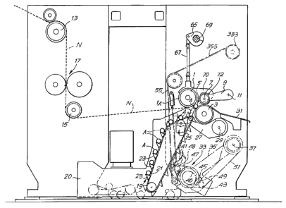
Referring first only to the members necessary for
the production of logs provided with winding core, the
rewinder of Fig. 1 includes a first winder roller 1 and a
second winder roller 3 which define a nip 5 through which
the web material N to be wound if fed. Indicated by lA is
the cylindrical surface of the roller 1. The nip 5 has, in
this condition, a cross dimension equal to or slightly
smaller than the diameter of the cores A on which the web
material is wound. A third winder roller 7, supported by
an oscillating arm 9 pivoted at il to the machine frame,
defines a winding space for the formation of logs. The
roller 7 moves gradually upwards about the axis 11 to allow
and control the increase of the diameter of the log in the
course of formation. The web material N is unreeled from a
feeding roll (not shown) and guided towards the winding
region by a series of driving and guiding rollers 13, 15.
Before reaching the winding region defined by the rollers
1, 3 and 7, the web material N goes through a perforator
unit 17, wherein it is perforated along transverse lines.
Numeral 19 generally indicates a means for
feeding the cores A on which the web material N is wound
for the production of logs. The means 19 includes an
endless conveyor 21 provided with a series of supports 23
on which the cores A are placed, which are picked up one by
one from a hopper container or the like (not shown). Each
core A passes a gluing unit 25 which applies a thin layer
of glue thereon to allow the leading edge of the web
material to be anchored thereto. The individual cores fed
by the conveyor 21 are picked up by an insertion means 27
pt .
,:..,
0
_ 4 _
pivoted at 29 to the machine frame and provided with an
oscillating intermittent motion which is synchronized with
the machine speed. Upon completion of a log, the insertion
means 27 inserts a new core A into the nip 5 between
rollers 1 and 3. The tearing of the web material, the
unloading of the completed log onto a surface 31, and the
start of the winding of a new log take place according to
known procedures.
The elements so far described allow the
production of logs provided with a winding core. However,
the machine is also arranged for producing rolls or logs of
web material N without a winding core. To this end, in this
exemplary embodiment, provision is made for a unit 33
carried by an oscillating arm 35 and pivoted at 37 to the
machine frame. In Fig. 1, the unit 33 is shown in dotted
lines in the position it takes up when not in use. When it
is desired to produce logs without a central core A, the
machine members are moved from the position Fig. 1 to that
of Fig. 2 .
As can be seen in Fig. 2, the core feeding means
19 has been shifted to the left and moved away from the
winding region. This is accomplished by placing said core-
feeding means on a motor-driven carriage 20.
The unit 33 has been moved in a clockwise
rotation from the withdrawn position of Fig. 1 to a
position in which it cooperates with the winding rollers 1
and 3, which have been brought closer to one another. At
the same time, the insertion means 27 moves, in
counterclockwise direction about the axis 29, from the
active position of Fig. 1 to a lower withdrawn position
(shown with dotted lines in Fig. 2).
The unit 33 is the subject of Canadian Patent
Application Serial No. 2, 100, 797, to which reference may be
made. Therefore, the construction of the unit 33 will be
described herein only generally. The said unit includes a
curved surface 41 which, when the unit is at the position
of Fig. 2, defines a channel, along with the surface of
roller 1, in which the web material N begins to wind up on
ti~~'..
V :~ ..r
~.,. _ 5 _ ,~
itself in the absence of a winding core. A motor 43 or
other suitable actuator, mounted on arm 35, through a first
flexible member 45, a cam 46, a second flexible member 47
and an eccentric system 48, causes an intermittent movement
bringing the surface 41 close to the cylindrical surface of
roller 1.
In practice, in the condition shown in Fig. 2,
the motor 43 is driven into rotation shortly before the end
of the winding of a log. This will cause the unit 33 (and
thus of surface 41) to move towards the roller 1 as a
result of the cooperation of cam 46 with a tappet 49
carried by an arm 51. The same movement of the motor 43
will also cause a movement of the surface 41 towards the
roller 1 through the action of the eccentric system 48. The
sum of the two oscillation motions brings the surface 41
into contact with the surface of roller 1 only once upon
every revolution of cam 46. This causes the web material N
to tear and the free leading edge thus formed to curl on
itself, to create a new log. The first turns thus formed
grow rapidly in diameter and roll along the surface 41 to
reach the nip 5 and pass therethrough into the winding
space defined by the rollers 1, 3 and 7. The passing of the
log in the course of formation through the nip 5 is
accomplished by the (temporary or constant) difference in
speed between the rollers 1 and 3. The procedures for
tearing the web material N and for beginning the winding of
the free edge on itself are illustrated in greater detail
in the above-mentioned Canadian Application Serial No.
2,100,797. The unit 33 may be made according to any of the
embodiments described in the above-mentioned patent
applications.
i:~.
3Cr ,.:
WO 94I29205 216 4 8 7 0 PCTlTT94/00075
- 6 -
In order to shift the unit 33 carried by arm 35 to
the active position of Fig. 2, a lifting system is
provided including a rotating actuator, schematically
shown at 53 , and a flexible member 55 anchored by one end
thereof to the actuator 53, by the opposite end to a fixed .
point 57 of the machine, and by the interposition of
resilient dampening means 59. The flexible member 55 is
driven around a small roller 61 carried by arm 51. The
lifting of arm 51, due to the winding of flexible member
55 over actuator 53, causes also the lifting of arm 35 and
thus of unit 33, owing to the cooperation between the
eccentric 46 and the tappet 49. In actual practice,
provision will be made, for two arms 35 and two arms 51,
one on either side of the machine, with corresponding
means 53, 55 for the lifting of the unit 33. In the
operating position, the arms 51 are kept by the flexible
element 55 against adjustable abutments (not shown in the
figure) which are disposed one on each side of the frame
and are independent of one another.
Because the formation of logs without winding core
produces a log as it enters the nip 5, with a much smaller
diameter than that of the winding cores A, the rewinder
according to the invention is provided with a system
allowing the winding rollers 1 and 3 to move close to each
other, in order to change the width of the nip 5 according
to the type of product being made.
In the embodiment of Figs. 1 and 2, provision is
made for a crank-connecting rod system 65, 67 driven by a
shaft 69. Said system moves roller 1 close to roller 3
when the rewinder is to form coreless logs, and thus the
axis of roller 1 is displaced from position X to position
X' (see Fig. 2). The displacement is obtained by moving an
arm 70 supporting roller 1, about a pivot 72. It will be
appreciated that provision may also be made for a motion a
causing the roller 3 to move close to roller 1. Moreover,
as can be seen by a comparison of Figs. 1 and 2, when
shifting from the production of core logs to that of
_ 7 _ ~ ~1~~ ~~
coreless logs, the path of the web material is changed as
well. The same mechanism 65 ,67, 69 which moves the roller
1 from position X to the position X~, may be used (if
controlled by a suitable servomotor) during the machine
operation to move the roller 1 during passing of the just-
started log between rollers 1 and 3. This in order to keep
at a minimum the squeezing of said log.
Figs. 3 and 4 show a different embodiment of the
rewinder according to the invention. In the description
which follows, reference will be first made to Fig. 3 which
shows the configuration used for the production of logs
with core correspond, in this case, to co-pending Canadian
Patent Application No. 2,158,751, to which reference can be
made. Numerals 101, 103, 107 designate the winding rollers
corresponding to rollers 1, 3, 7 of Fig. 1. Numeral 101A
indicates the cylindrical surface of roller 101. Indicated
by 105 is the nip defined by rollers 101 and 103. The
roller 107 is supported by an oscillating arm 109 hinged at
111 to the machine frame. The roller 107 moves gradually
upwards about the axis 111 to allow and control the
increase of the diameter of the log in the course of
formation. The web material N is unreeled from a feeding
parent roll (not shown) and guided towards the winding
region by a series of driving and guiding rollers 113, 115.
Before reaching the winding region defined by rollers 101,
103 and 107, the web material N passes through a
perforation group 117, where it is perforated along
transverse lines.
Numeral 119 generally indicates a means for
feeding the cores A on which the web material N is to be
wound for the production of logs. The means 119 includes an
endless conveyor 121 provided with a series of supports 123
which pick up the cores one at a time from the inclined end
plane 120 of a hopper container or the like (not shown).
Each core A passes a gluing unit 125 by means of which a
thin layer of glue is applied thereon allowing
,..':
WO 94/29205 216 4 8 l 0 PCT/IT94/00075
_ g _
the leading edge of the web material to be anchored on
said cores. The individual cores fed by conveyor 121 are
then removed from the conveyor by an insertion means 127
made up of a plate rotating about an axis 128 coincident
with the axis of rotation of one of the driving wheels of
the endless conveyor 121.
The insertion means 127 moves each core A into a
channel 130 defined on one side by the cylindrical surface
of the roller 101 and at the other side by a series of
shaped plates laminae 132. Each core A is inserted into
the channel 130 at the end of the winding of a log, and
the free edge of the web material, obtained by a tearing
of said material in a manner to be described below, is
anchored by the glue on the core as the core is inserted
within the channel. The core begins the winding by rolling
along the lower fixed curved surface defined by the plates
132, until it reaches the nip 105. Here, the core comes
into contact with the roller 103 which rotates at a
peripheral speed which is (constantly or temporarily) less
than that of roller 101, thereby causing the transit of
the core A and the log in the course of formation into the
winding space defined by the three rollers 101, 103, 107.
The tearing of the web material N is caused.by a
series of pressers 134 which, by rotating about their own
axis 136, pass between the laminae 132 , and pinch the web
material between .their own surface and the surface of
roller 101. The pressers 134 rotate intermittently, and
the peripheral speed of the surface thereof which presses
against the roller 101 is less than the peripheral speed
of the latter. The difference in speed causes the web
material N to tear according to the description specified
in the Italian Patent Application No. FI93A58. ~~~
In order to produce coreless logs by means of the
machine of Figs. 3 and 4, provision is made for moving the
upper part of conveyor 121, the gluing group 125, the
insertion means 127, and the assembly formed by the axle
supporting pressers 134 and by plates 132 away from the
2164870
WO 94I29205 PCT/IT94/00075
- 9 -
winding region. Such moving away is accomplished by a
translation along roller guide means 140. At the same
time, a group 133 (corresponding substantially to, group
33) which is supported by a shaft 137 coincident, in this
case, with the axis of rotation of roller 103, is brought
near winder roller 101. Numeral 141 indicates a surface
corresponding to the surface 41 of Figs. 1 and 2.
Indicated by 143, 145, 146, 147, 148 and 149 are elements
corresponding to those indicated by 43, 45, 46, 47, 48 and
49 of Figs. 1 and 2. The arm 151 carrying the tappet 149
is connected to a cylinder-piston actuator 153 which has
the same functions as the system 53, 55 of Figs. 1 and 2.
154 denotes an adjustable abutment against which the
respective arm 151 rests when in working condition.
The system for moving the rollers 101 and 103
close to one another has been omitted in Figs. 3 and 4,
said system being similar to the one shown in Figs. 1 and
2.
It will be appreciated that the configuration of
the rewinder for the production of logs provided with
winding core may be different from that illustrated in the
two embodiments, and in practice may be chosen from any of
the configurations currently known and used in the
machines able to produce exclusively logs with winding
core.
Fig. 5 shows an embodiment in which the winding
without core is carried out through the direct cooperation
of the winder rollers 101 and 103. Parts corresponding to
the embodiment of Figs. 3 and 4 are indicated by the same
numeral reference. Numeral 201 indicates an arm supporting
the roller 101, said arm being pivoted at 203. Numeral 205
' indicates a resilient connecting rod in the form of a
cylinder-piston system and connected to an actuator 207.
The system 205, 207 moves the roller 101 about the pivot
203. By means of a suitably longer approaching stroke, the
roller 101 is brought close to roller 103 to carry out the
winding without core. In such close relationship, the core
WO 94I29205 216 4 8 7 0 PCT/IT94/00075
- 10 -
conveying group is moved away as shown in the embodiment
of Fig. 4. The coreless winding takes place, in this case,
with the same procedures as described in corresponding
U.S. Patent Application Ser. No. 090,519, the content of
which is incorporated by reference in the present cr
description. The surfaces of rollers 101 and 103 move
cyclically close to each other to pinch the web material
between them and thus cause said web material to tear and
roll up upon itself after tearing.
It is understood that the drawing shows an
exemplification given only as a practical demonstration of
the invention, as this may vary in the forms and
dispositions without, nevertheless, coming out from the
scope of the idea on which said invention is based. The
possible presence of reference numbers in the appended
claims has the purpose of facilitating the reading of the
claims, reference being made to the description and the
drawing, and does not limit the scope of the protection
represented by the claims.