Note: Descriptions are shown in the official language in which they were submitted.
~16~~~7~
WO 95/01485 PCT/SE94/00590
1
i t
The present invention relates to a joist for building
constructions, comprising an elongated, form-stable body
with a flat outer side and an inner side, said body being
provided with a plurality of circular through-holes
spaced from each other and extending perpendicularly to
and between said outer and inner sides, the walls of the
holes being provided with threads with predetermined
pitch, and a plurality of load-bearing space and level
adjusters of straight, circular cylindrical shape, each
space and level adjuster having an external thread of the
same pitch as the thread of the hole wall and being
provided with engagement means accessible from the
outside of the joist body for co-operation with a turning
device, said space and level adjusters having a diameter
of 10-40 mm, preferably 15-25 mm, and being screwed into
said holes with their front portions protruding from the
joist body to form an air gap between the supporting
surface and the joist body and to adjust the outer side
of the joist body at a desired level, the remaining
portion of the space and level adjuster being in firm
thread engagement with the joist body and the rear end
being located below or in plane with the outer side of
the joist body.
When building a floor construction, for instance, solid
floor joists are used that usually consist of timber and,
due to their sealing effect, the air circulation under
the finished floor is poor, or even non-existent. This
often contributes to problems of damp and mould
occurring. Furthermore, the floor joist is generally in
direct contact with the supporting surface and if this is
damp the floor joist may absorb this dampness and the
moisture-absorbing parts gradually rot. Expensive
clearance work and reconstruction are then required when
the resultant unavoidable damage is to be repaired. The
WO 95/01485 PCT/SE94/00590
ms~~79 2 _
level of the floor is also determined by the dimension of
the floor joists and the range of floor joists can
therefore be relatively large if all requirements for
different floor levels are to be satisfied. Unevenness of
the supporting surface is another difficulty with regard
to installing the joists at the correct level.
The object of the present invention is to greatly reduce
the problems mentioned above and provide a joist that
will enable air to circulate as well as being easy to
install at the desired level, and which can be easily and
quickly produced even directly on site where the joists
are to be used.
The joist according to the present invention is
substantially characterized in that said threads in the
holes are effected directly in the joist body, that said
threads on the space and level adjusters extend from end
to end, that the space and level adjusters have a length
such that a rear portion situated inside the joist body
in order to maintain the requisite thread engagement, has
a part-length of at least 10 mm, preferably at least
20 mm, whereas the front portion has a part-length of at
least 1 mm, preferably at least 5 mm, in order to form
said air gap, and that the space and level adjusters are
arranged in the central plane of the joist body,
bisecting the outer and inner sides at right angles
and/or in two rows and alternating on each side of the
central plane of the joist body.
The invention will be described further in the following
with reference to the drawings.
Figure 1 is a side view of a joist according to the
present invention.
Figure 2 is a side view of the joist according to Figure 1.
~I6~~79
WO 95/01485 PCT/SE94/00590
3
Figure 3 is an end view of the joist according to Figure 1.
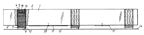
The joist shown in the drawings comprises a body 1 which
is generally straight and elongated in shape. The joist
body 1 has rectangular cross section with a flat outer
side 2 and a flat inner side 3 parallel with the outer
side 2. C denotes a vertical central plane through the
joist body.
The joist body is provided with a plurality of circular,
vertical through-holes 4 arranged at predetermined
distance from each other and extending perpendicularly to
and between said outer and inner sides 2, 3. The distance
between two adjacent holes 4 is suitably between 5 and
200 cm, a preferred distance being between 30 and 60 cm.
The distance chosen in each case between two adjacent
holes is suitably constant along the whole length of the
joist body 1. The walls of the holes 4 have threads with
predetermined pitch and the threads 5 are effected in
advantageous manner directly in the joist body 1, thus
eliminating the necessity for special inserts and so that
drilled and threaded holes 4 can be produced simply and
quickly, preferably at the same instant. The entire hole
4 is threaded, i.e. from the outer side 2 to the inner
side 3 of the joist body.
Furthermore, the joist comprises a plurality of load-
-bearing space and level adjusters 6, similar to the
shaft of a bolt, having straight, circular, cylindrical
form. Each space and level adjuster has an external
thread 7 with the same pitch as the thread 5 of the wall
of the hole, and is also provided with engagement means 8
freely accessible from the outside 2 of the joist body
for co-operation with a turning device (not shown). The
entire length of the space and level adjuster 6 is
threaded externally, i.e. the thread 7 extends from the
WO 95/01485 PCT/SE94/00590
21~~47
4
front end to the rear end of the adjuster. In the
embodiment shown the space and level adjuster 6 is
provided with a hexagon socket 9 to receive a
corresponding turning device in the form of a hexagon
wrench, the hexagon socket 9 being preferably of limited
depth, i.e. not through-running, to provide a bottom part
which is in turn provided with a narrower through-hole
11 intended for a nail or screw to be driven into the
supporting surface 14 to secure the space and level
10 adjuster 6 to the supporting surface 14, but preferably
without preventing turning of the space and level
adjuster 6 in case further level adjustment should be
required. In an alternative embodiment the engagement
means consists of a transverse groove in the rear end of
the space and level adjuster, for co-operation with a
screwdriver. A combination of groove and hexagon socket
is also possible.
The space and level adjusters 6 are thus screwed into the
holes 4 in the joist body, their front portions 12
protruding out of the joist body 1 to form an air gap 13
between the supporting surface 14 and the joist body and
also to adjust the outer side 2 of the joist body to a
desired level. The remainder of the space and level
adjuster 6, i.e. the rear portion 15 situated inside the
joist body 1 is in firm thread engagement with the joist
body, the rear end 16 of the space and level adjuster
then being located below or flush with the outer side 2
of the joist body.
The diameter of the space and level adjuster 6 is chosen
to ensure that it is sufficiently strong to be able to
carry the loads that will rest on and affect the joists,
without the space and level adjuster 6 being bent and so
that the thread engagement area is sufficiently large to
ensure strong thread engagement even when the rear end 16
of the space and level adjuster 6 is located below the
WO 95/01485 J , . PCT/SE94I00590
outer side 2 of the joist body. A suitable diameter is
10-40 mm, preferably 15-25 mm. Furthermore, the length of
the space and level adjuster 6 is chosen such that a
strong thread engagement is obtained even when the rear
5 end 16 of the space and level adjuster 6 is located at a
distance from and below the outer side 2 of the joist
body, i.e. the portion 15 situated inside the joist body
is sufficiently long in combination with said selected
diameter, and also that a desired maximal level
adjustment can be achieved. A suitable length is 0-3 cm
longer than the distance between the outer side 2 and the
inner side 3, measured after final mounting. The length
may be greater at the start of mounting and part of the
space and level adjuster 6 will also protrude from the
outer side 2 of the joist body when the level adjustment
has been completed. The protruding piece is then sawn off
and the surface section ground down to be flush with the
outer side 2 of the joist body. When the space and level
adjuster 6 is utilised for maximal level adjustment in
each individual case, the length of the rear portion 15
of the space and level adjuster 6 located in the joist
body is at least 10 mm, preferably at least 20 mm,
depending on the load to be placed on the joist body 1
and space and level adjusters 6 by the rest of the
building construction and external heavy objects. The
front portion 12 has a part-length of at least 1 mm,
preferably at least 5 mm to provide the air gap desired
in each particular case.
In the embodiment shown the space and level adjusters 6
are arranged in the middle of the joist body, i.e. in the
central plane of the joist body. In an alternative
embodiment they may be arranged in two rows on each side
of said central plane if the width of the joist body
permits. This allows the joist to be placed standing on a
floor surface, with the outer side 2 in horizontal
position.
WO 95/01485 ~ ~ ~ ~ PCT/SE94/00590
6
The joist also comprises support members 17 for
insulation material. In the embodiment shown these
support members consist of rectangular, deformable metal
plates having a width less than or equal to the width of
the joist body 1 and a length greater than the width of
the joist body, in order to form free end portions 18, 19
situated at the sides of the joist body to support sheets
of insulation. Said end portions 18, 19 are suitably
3-6 cm in length. Each plate 17 is mounted on the inner
side 3 of the joist body by means of a central screw 20
to retain the plate 17 while permitting it to be turned
90° from an inner resting position to an outer, operative
position to support the insulation. According to another
preferred embodiment of the support members, each
consists of an angle profile having a U-shaped part with
two parallel side pieces, and also two wings protruding
laterally away from each other at right angles in order
to support insulating material between two joists, the
U-shaped part being designed to straddle the joist from
above, the connecting piece that joins the two parallel
side pieces together, being in contact with the upper
side of the joist. The angle profile is preferably made
of a stable sheet-metal blank that has been bent at right
angles along four score lines.
Some of the plates 17 may be used temporarily as support
for the joist to keep it in upright position in the same
way as the space and level adjusters 6 located at the
side of the central plane C. For this purpose the plates
17 are turned to the operative position and their end
portions 18, 19 are bent down to form legs that
temporarily support the joist on a floor surface. Once
level adjustment has been performed the end portions are
bent up to position in order to support sheets of
insulating material placed between the joists. If a joist
is to be placed close to and along a wall or the like,
WO 95/01485 ~ ~ ~ PCTISE94100590
7
the end portions 18, 19 of the plates 17 are bent up
against the side of the joist body 1.
The joist according to the invention is easy to
manufacture and easy to install on all types of surfaces
for floors, walls and ceilings. The actual joist body 1
may be made of any suitable material such as wood,
plastic or metal, e.g. steel, that provides a form-stable
joist body with sufficient bearing capacity. The joist
body may be solid or hollow. In the latter case, it must
be ensured that the holes 4 have sufficient wall surface
for threading. The space and level adjusters 6 are
suitably manufactured from a hard plastic material,
giving them the required bearing capacity and also being
resistant to ageing.
When the joist body consists of wood or plastic, the
joists can be supplied in different dimensions or even in
continuous lengths for cutting with ordinary tools, and
joined in suitable manner. The space and level adjusters
may even be mounted in the joists on site, in which case
the joist body may be predrilled or drilling may be
performed on site.