Language selection

Search

Patent 2165502 Summary

Third-party information liability

Some of the information on this Web page has been provided by external sources. The Government of Canada is not responsible for the accuracy, reliability or currency of the information supplied by external sources. Users wishing to rely upon this information should consult directly with the source of the information. Content provided by external sources is not subject to official languages, privacy and accessibility requirements.

Claims and Abstract availability

Any discrepancies in the text and image of the Claims and Abstract are due to differing posting times. Text of the Claims and Abstract are posted:

  • At the time the application is open to public inspection;
  • At the time of issue of the patent (grant).
(12) Patent: (11) CA 2165502
(54) English Title: SOLENOID VALVE CONTROL SYSTEM
(54) French Title: SYSTEME DE COMMANDE D'ELECTROVANNES
Status: Expired
Bibliographic Data
(51) International Patent Classification (IPC):
  • G05D 7/06 (2006.01)
  • F15B 13/00 (2006.01)
  • F16K 27/00 (2006.01)
  • F16K 31/06 (2006.01)
(72) Inventors :
  • BONACORSI, DENNIS L. (United States of America)
  • CHILL, CHARLES W. (United States of America)
  • SMITH, WILLIAM S. (United States of America)
  • WELKER, JEFFREY H. (United States of America)
(73) Owners :
  • NUMATICS, INC. (Not Available)
(71) Applicants :
(74) Agent: MARKS & CLERK
(74) Associate agent:
(45) Issued: 2000-02-22
(22) Filed Date: 1995-12-18
(41) Open to Public Inspection: 1996-09-11
Examination requested: 1998-09-03
Availability of licence: N/A
(25) Language of filing: English

Patent Cooperation Treaty (PCT): No

(30) Application Priority Data:
Application No. Country/Territory Date
08/402,004 United States of America 1995-03-10

Abstracts

English Abstract

A plurality of solenoid control valves each mounted on a module of a manifold with a terminal block for each valve removably received in the manifold and having at least three terminals. A printed circuit board with a microprocessor and a coil driver mounted on the board has three spaced apart electric connectors releasably secured to separate terminals of the same terminal block and each having a shank received in a hole through the circuit board and electrically connected to a printed circuit on the board by solder to both mount and support the circuit board on the terminal block and provide outputs of the coil driver to the coils of two solenoids for controlling the application of electric power to them. An auxiliary circuit board with another coil driver and electric connectors mounted on another terminal block is daisy chained with the microprocessor for controlling the application of electric power to additional solenoid coils. Additional solenoid coils may also be connected to the outputs of the coil drivers for controlling through the microprocessor the application of electric power to them.


French Abstract

Une pluralité d'électrovannes dont chacune est montée sur un module d'un collecteur avec un bornier pour chaque vanne reçu de façon amovible dans le collecteur et comportant au moins trois bornes. Une carte de circuits imprimés dotée d'un microprocesseur et d'un circuit d'attaque de bobine comporte trois connecteurs électriques espacés entre eux, fixés de façon amovible à des bornes distinctes du même bornier et ayant chacun une tige reçue dans un orifice à travers la carte de circuits imprimés et connectée électriquement à un circuit imprimé de la carte par soudure afin de monter et de soutenir la carte de circuits imprimés sur le bornier et de fournir les sorties du circuit d'attaque de bobine aux bobines de deux électrovannes pour contrôler l'application d'alimentation sur celles-ci. Une carte de circuits imprimés auxiliaire avec un autre circuit d'attaque de bobine et des connecteurs électriques montés sur un autre bornier est connectée en série au microprocesseur afin de contrôler l'application d'alimentation électrique sur des bobines de solénoïde supplémentaires. Les bobines de solénoïde supplémentaires peuvent également être connectées aux sorties des circuits d'attaque de bobine afin de contrôler à travers le microprocesseur l'application d'alimentation électrique sur celles-ci.

Claims

Note: Claims are shown in the official language in which they were submitted.


What Is Claimed Is:


1.

A control system comprising a manifold, at least one
solenoid control valve carried by the manifold, a terminal block
received in the manifold for each solenoid valve, said terminal
block having at least three individual electric terminals
thereon, at least two electric solenoids each operably associated
with a fluid control valve carried by the manifold, a
communication card having a circuit board, a micro processor,
on the circuit board a coil driver on the circuit board capable
of controlling a plurality of solenoid coils of control valves,
a printed circuit on the circuit board, the microprocessor
controlling the coil driver, and at least three spaced apart
electrical connectors each constructed and arranged to be
releasably secured to a separate terminal of the same terminal
block and each having a shank received in a hole through the
circuit board and electrically connected to the printed circuit
both to mount and support the circuit board on the terminal
block and to provide outputs of the coil driver to the coils of
two solenoids for controlling the application of electric power
to each of the coils of said two solenoids.


-19-


2.

The control system of claim 1 wherein the shank of
each terminal is connected to a portion of the printed circuit
by solder.
3.
The control system of claim 1 which also comprises a
plug carried by the circuit board and electrically connected
with the mircoprocessor for providing a daisy chain connection
of the microprocessor for at least one auxiliary circuit board
having a second coil driver capable of controlling a plurality
of solenoid coils of control valves.
4.
The control system of claim 3 which also comprises a
another plug carried by the circuit board and electrically
connected with outputs of the coil driver for each of a plurality
of coils of solenoids of control valves for controlling the
application of electric power to such coils of the solenoids.
5.
The control system of claim 1 which also comprises a
plug carried by the circuit board and electrically connected
with outputs of the coil driver for each of a plurality of coils
of solenoids of control valves for controlling the application
of electric power to such coils of the solenoids.
6.
The control system of claim 1 wherein the
microprocessor is constructed and arranged to be utilized in a


-20-


bus network with a single address having multiple inputs to the
microprocessor to control the outputs of the coil driver.
7.
The control system of claim 6 which also comprises a
communication plug carried by said circuit board and electrically
connected with said microprocessor for a programmable controller
or a digital computer to address the microprocessor to control
the outputs of the coil driver for controlling the application
of electric power to each of a plurality of coils of solenoids
of the control valves.
8.
The control system of claim 1 which also comprises a
communication plug carried by said circuit board and electrically
connected with said microprocessor for a programmable or a
digital computer to address the microprocessor to control the
outputs of the coil driver for controlling the application of
electric power to each of a plurality of coils of solenoids of
control valves.
9.
The control system of claim 1 which also comprises a
recess in said manifold for each terminal block, each said
recess opens to the exterior of the manifold, the terminal block
for each solenoid valve is slidably received in an associated
recess in the manifold and is removable from its associated
recess, and a removable cover for each recess which is releasably


-21-


securable to the manifold to enclose the terminal block including
any communication card received thereon within the manifold.
10 .
The control system of claim 9 which also comprises a
detent carried by each terminal block for releasably retaining
the terminal block in the manifold.
11 .
The control system of claim 9 which also comprises
for each terminal block at least one guide rail and an associated
follower, one of the guide rail and follower being carried by
the manifold and the other of the guide rail and follower being
carried by the terminal block, and the guide rail and follower
cooperating to align and guide the terminal block during
insertion of the terminal block into the recess in the manifold
and removal of the terminal block from the recess.
12.
The control system of claim 10 which also comprises
for each terminal block at least one guide rail and an associated
follower, one of the guide rail and follower being carried by
the manifold and the other of the guide and rail follower being
carried by the terminal block, and the guide rail and follower
cooperating to align and guide the terminal block during
insertion of the terminal block into the recess in the manifold
and removal of the terminal block from the recess.


-22-


13.
The control system of claim 1 which also comprises a
voltage regulator on the circuit board for supplying a regulated
voltage to the coil driver for operation of the coil driver by
the microprocessor.
14.
The control system of claim 13 which also comprises
a plug on the circuit board and electrically connected with the
voltage regulator for supplying power to the voltage regulator.


15.
The control system of claim 1 which also comprises
an auxiliary driver card having a second circuit board, a second
coil driver on said second circuit board and capable of
controlling a plurality of solenoid coils of control valves, a
second printed circuit on said second circuit board, and at
least three spaced apart second electrical connectors each
constructed and arranged to be releasably secured to a separate
terminal of a second terminal block and each having a shank
received in a hole through the second circuit board and
electrically connected to the second printed circuit both to
mount and support the second circuit board on the second terminal
block and to electrically connect outputs of the second coil
driver to the coils of two solenoids for controlling the
application of electric power to each of the coils of the two
last mentioned solenoids, and the second coil driver being
-23-


electrically connected in a daisy chain with the microprocessor
for controlling the second coil driver by the microprocessor.
16.
The control system of claim 15 wherein the shank of
each second electrical connector is connected to a portion of
the second printed circuit by solder.
17.
The control system of claim 15 which also comprises
a plug carried by the second circuit board and electrically
connected with the mircoprocessor for providing a daisy chain
connection of the microprocessorwith the second coil driver for
controlling the outputs of the second coil driver.
18.
The control system of claim 17 which also comprises
a another plug carried by second the circuit board and
electrically connected with outputs of the second coil driver
for providing outputs of the second coil driver to control
application of electric power to solenoid coils of control
valves.
19.
The control system of claim 15 which also comprises
a plug carried by the circuit board and electrically connected
with outputs of the second coil driver for providing outputs
for controlling the application of electric power to solenoid
coils of control valves.


-24-


20.
The control system of claim 15 wherein the
microprocessor is constructed and arranged to be utilized in a
bus network with a single address having multiple inputs to
control both of the coil drivers.
21.
A control system comprising a manifold, at least two
solenoid control valves carried by the manifold, a terminal
block received in the manifold for each solenoid valve, said
terminal block having at least three individual electric
terminals thereon, at least three electric solenoids each
operably associated with a control valve carried by the manifold,
a communication card having a first circuit board, a micro
processor, on the first circuit board, a coil driver on the
first circuit board and capable of controlling a plurality of
solenoid coils of control valves, a first printed circuit on
the first circuit board, the microprocessor controlling the
first coil driver, and at least three spaced apart electrical
connectors each constructed and arranged to be releasably secured
to a separate terminal of the same terminal block and each having
a shank received in a hole through the first circuit board and
electrically connected to the first printed circuit both to
mount and support the first circuit board on the terminal block
and to provide outputs of the first coil driver to coils of the
solenoids for controlling the application of electric power


-25-


the solenoid coils, an auxiliary driver card having a second
circuit board, a second coil driver on said second circuit board
and capable of controlling a plurality of solenoid coils of
control valves, a second printed circuit on said second circuit
board, and at least three spaced apart second electrical
connectors each constructed and arranged to be releasably secured
to a separate terminal of a second terminal block and each having
a shank received in a hole through the second circuit board and
electrically connected to the second printed circuit both to
mount and support the second circuit board on the second terminal
block and to provide outputs of the second coil driver to coils
of the solenoids for controlling the application of electric
power to the last mentioned solenoid, and the second coil driver
being electrically connected in a daisy chain with the
microprocessor for controlling of the second coil driver by the
microprocessor.
22.
The control system of claim 21 which also comprises
a plug carried by the first circuit board and electrically
connected with the mircoprocessor and providing a daisy chain
connection of the microprocessor with the second coil driver
on the second circuit board for controlling the seond coil
driver outputs by the microprocessor.
-26-


23.
The control system of claim 21 which also comprises
a plug carried by the first circuit board and electrically
connected with outputs of the first coil driver for each of a
plurality of coils of solenoids for controlling the application
of electric power to such solenoid coils.
24.
The control system of claim 21 wherein the
microprocessor is constructed and arranged to be utilized in a
bus network with a single address having multiple inputs to the
microporcessor to control the outputs of both the first and
second coil driver.
25.
The control system of claim 24 which also comprises
a communication plug carried by said first circuit board and
electrically connected with said microprocessor for a
programmable controller or a digital computer to address the
microprocessor to control both the coil drivers for controlling
the application of electric power to each of a plurality of
coils of solenoids of control valves.
26.
The control system of claim 21 which also comprises
a communication plug carried by said first circuit board and
electrically connected with said microprocessor for a
programmable controller or a digital computer to address the
microprocessor to control both the coil drivers controlling the


-27-


application of electric power to each of a plurality of coils
of solenoids of control valves.
27.
The control system of claim 21 which also comprises
a recess in said manifold for each terminal block, each said
recess opens to the exterior of the manifold, the terminal block
for each solenoid valve is slidably received in an associated
recess in the manifold and is removable from its associated
recess, and a removable cover for each recess which is releasably
securable to the manifold to enclose the terminal block including
any communication card received thereon within the manifold.
28.
The control system of claim 21 which also comprises
a voltage regulator on the first circuit board for supplying a
regulated voltage to the first coil driver for operation of the
first coil driver by the microprocessor.
29.
For a control system having a manifold, at least one
solenoid control valve carried by the manifold, a terminal block
received in the manifold for each solenoid valve and having at
least three individual electric terminals thereon, and at least
two solenoids each having an electric coil and operably
associated with a control valve carried by the manifold, a
communication card comprising; a circuit board, a microprocessor
on the circuit board, a coil driver on the circuit board and


-28-


capable of controlling a plurality of solenoid coils of control
valves, the microprocessor controlling the coil driver, a
printed circuit on the circuit board, and at least three spaced
apart electrical connectors each constructed and arranged to
be releasably secured to a separate terminal of the same terminal
block and each having a shank received in a hole through the
circuit board and electrically connected to the printed circuit
both to mount and support the circuit board on the terminal
block and to provide outputs of the coil driver to the coils of
two solenoids for controlling the application of electric power
to each of the coils of the two solenoids.
30.
The control system of claim 29 wherein the shank of
each terminal is connected to a portion of the printed circuit
by solder.
31.
The control system of claim 29 which also comprises
a plug carried by the circuit board and electrically connected
with the mircoprocessor for providing a daisy chain connection
of the microprocessor with at least one auxiliary circuit board
having a second coil driver capable of controlling a plurality
of solenoid coils of control valves.
32.
The control system of claim 31 which also comprises
another plug carried by the circuit board and electrically


-29-


connected with outputs of the coil driver for each of a plurality
of coils of solenoids of control valves for controlling the
application of electric power to such coils of the solenoids.
33.
The control system of claim 29 which also comprises
a plug carried by the circuit board and electrically connected
with outputs of the coil driver for each of a plurality of coils
of solenoids of control valves for controlling the application
of electric power to such coils of the solenoids.
34.
The control system of claim 29 wherein the
microprocessor is constructed and arranged to be utilized in a
bus network with a single address having multiple inputs to the
microprocessor to control the outputs of the coil driver.
35.
The control system of claim 34 which also comprises
a communication plug carried by said circuit board and
electrically connected with said microprocessor for a
programmable controller or a digital computer to address the
microprocessor to control the outputs of the coil driver for
controlling the application of electric power to each of a
plurality of coils of solenoids of control valves.
36.
The control system of claim 29 which also comprises
a communication plug carried by said circuit board and


-30-


electrically connected with said microprocessor for a
programmable controller or a digital computer to address the
microprocessor to control the outputs of the coil driver for
controlling the application of electric power to each of a
plurality of coils of solenoids of control valves.
37.
The control system of claim 29 which also comprises
a voltage regulator on the circuit board for supplying a regulated
voltage to the coil driver for operation of the coil driver by
the microprocessor.
38.
For a control system having a manifold, at least two
solenoid control valves carried by the manifold, a terminal
block received in the manifold for each solenoid valve and
having at least three individual electric terminals thereon,
and at least four solenoids each having an electric coil and
being operably associated with a control valve carried by the
manifold, an auxiliary coil driver card comprising, a circuit
board, a coil driver on the circuit board and capable of
controlling a plurality of solenoid coils of control valves, a
printed circuit on the circuit board, and at least three spaced
apart electrical connectors each constructed and arranged to
be releasably secured to a separate terminal of the same terminal
block and each having a shank received in a hole through the
circuit board and electrically connected to the printed circuit
-31-


both to mount and support the circuit board on the terminal
block and to provide outputs of the coil driver to the coils of
two solenoids for controlling the application of electric power
to each of the coils of these two solenoids.
39.
The control system of claim 38 wherein the shank of
each terminal is connected to a portion of the printed circuit
by solder.
40.
The control system of claim 38 which also comprises
a plug carried by the circuit board and electrically connected
with the coil driver for providing a daisy chain connection of
the coil driver with a microprocessor on another circuit board
for controlling the outputs of the coil driver.
41.
The control system of claim 40 which also comprises
another plug carried by the circuit board and electrically
connected with outputs of the coil driver for each of a plurality
of coils of solenoids of control valves for controlling the
application of electric power to such coils of the solenoids.
42.
The control system of claim 38 which also comprises
a plug carried by the circuit board and electrically connected
with outputs of the coil driver for each of a plurality of coils


-32-


of solenoids of control valves for controlling the application
of electric power to such coils of the solenoids.
43.
The control system of claim 40 which also comprises
a voltage regulator on the circuit board for supplying a regulated
voltage to the coil driver for operation of the coil driver by
the microprocessor.
44.
The control system of claim 38 which also comprises
a plug on the circuit board and electrically connected with the
voltage regulator for supplying power to the voltage regulator.


-33-

Description

Note: Descriptions are shown in the official language in which they were submitted.


`7~
21 65502


(#008)
SOLENOID V~LVE CONT~OL


Field of the Invention
This invention relates to solenoid actuated fluid
control valves and more particularly to an electronic system
for actuating and controlling solenoid valves.
Background of the Invention
Valves for controlling the flow of hydraulic and
pneumatic fluid which are actuated by one or two electric
solenoids are known and have been used in automated manufacturing
equipment, production lines and numerous industrial applications
for many years. Frequently, a plurality of these solenoid
actuated valves are mounted on a manifold having a plurality
of passages for supplying fluid to the valves and providing
connecting passages for connecting fluid couplings to various
outlet ports of each valve. For many years, each solenoid of
each valve was separately electrically wired into an electrical
or electronic system for supplying power to and controlling the
cycling of each solenoid as required for each application in
which the valves were used.
More recently, programmable logic controllers and
suitably programmed digital computers have been utilized to
cycle and control solenoid actuated valves in many automated
machinery, equipment, and production line applications.
Typically, the controller or computer actuates an electronic


21 65502


switching device or even a relay which is in a location remote
from the solenoid valve and hence requires many long runs of
power feed wires between the switching device and each solenoid
of each valve. Thus, there is a need for a system which greatly
reduces the time, effort, expense, complexity and quantity of
wire required to power and operably connect a plurality of
solenoid actuated valves with a programmable controller or a
digital computer for cycling and controlling solenoid valves
in various automated machinery, equipment production lines and
other industrial applications.
Summary of the Invention
A serial communication system for cycling and
controlling a plurality of solenoid actuated valves with a
programmable logic controller or a digital computer. Each of
a plurality of solenoid valves is removably mounted on a module
of a manifold which has a terminal block for electrical connection
with the solenoids of each valve. A circuit board is removably
mounted on one terminal block by three electrical connectors
and has both a coil driver and a microprocessor communicating on
a bus network with the programmable controller or computer to
control the coil driver for applying electric power to each of
a pluralilty of solenoid coils of the valves. The three
electrical connectors are each releasably securable to separate
terminals of the same terminal block and have a shank received in
a hole through the board and electrically connected to a


21 65502


portion of its printed circuit to both mount the board and
supply power to two solenoid coils. If required to control all
of the valves on a manifold, one or more additional circuit
boards containing additional coil drivers can be removably
mounted on other terminal blocks of the manifold and daisy
chained with the microprocessor. This permits a single
microprocessor utilizing a single address to cycle and control
a large number of solenoid valves. Preferably, to facilitate
installation and replacement, each circuit board has plug-in
connectors and each manifold has separate quick connectors for
solenoid power and bus line communications.
Objects, features and advantages of this invention
include a solenoid valve communication control system which
greatly decreases the quantity of wire and number of wires
required, is compact and contained in the manifold, has circuit
cards which are easily installed and removed, permits additional
solenoid valves and coil driver circuit cards to be added as
needed, requires far fewer addresses on a bus sys~em, can be
easily installed in the field on existing solenoid valves with
manifolds not having an electronic control system, can use the
same communication circuit card with different communication
protocols, can use the same auxiliary coil driver circuit card
regardless of the communication protocal required, substantially
decreases assembly, wiring and installation, time, effort and


2 1 65502


expense, and is rugged, durable, reliable, easily replaceable,
and of relatively simple design and economical manufacture,
assembly and installation.
Brief Description of the Drawinqs
These and other objects, features and advantages of
this invention will be apparent from the following detailed
description, appended claims and accompanying drawings in which:
FIG. 1 is a perspective view of a plurality of solenoid
actuated control valves mounted on a modular manifold and
embodying the electronic communication control system of this
invention;
FIG. 2 is a top view of one module of the manifold;
FIG. 3 is a side view partially in section of the
manifold module;
FIG. 4 is an end view taken on line 4-4 of FIG. 3 with
the cover removed of the manifold module;
FIG . 5 iS a fragmentary exploded top view of a manifold
~odule with a communication circuit card on its terminal block;
FIG. 6 iS a fragmentary and exploded side view of the
module of FIG. 5 and its terminal block and communication circuit
card;
FIG. 7 iS an end view of the terminal block and
communication circuit card received in the manifold;
FIG. ~ iS a top view of a terminal block;
FIG. 9 is a front view of the terminal block;
FIG. 10 is a rear view of the terminal block;

21 65502


FIG. 11 is a front view of the communication circuit
card;
FIG. 12is a top view of the communication circuit card;
FIG. 13 is a bottom view of the communication circuit
card;
FIG. 14 is a side view of the communication circuit
card;
FIG. 15 is a front view of an auxiliary coil driver
circuit card;
FIG. 16 is a top view of the auxiliary coil driver
circuit card;
FIG. 17 is a bottom view of the auxiliary coil driver
circuit card;
FIG. 18 is a side view of the auxiiliary coil driver
circuit card;
FIG. 19 is a schematic wiring diagram for the terminal
blocks and circuit cards of the electronic control system;
FIG. 20 is a top view of another manifold module
showing the communication circuit card mounted on a four post
terminal block of the module; and
FIG . 21 is a front view of the manifold module of
FIG. 20.
Detailed Description
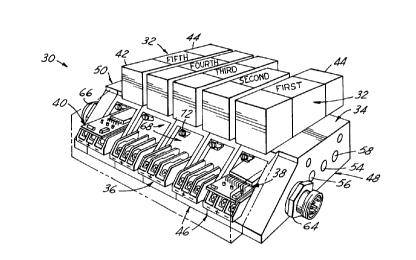
FI G . 1 i 11 us trates a pneumatic solenoid control valve
and manifold assembly 30 embodying this invention which has a


21 65502


pluralilty of solenoid control valves 32 each received on a
manifold 34 with a terminal block 36 for each valve. A
communication card 38 is removably mounted on one of the terminal
blocks for communicating through a bus network with a
programmable logic controller or programmed digital computer
to sequence, cycle and control the solenoid valves. An auxiliary
coil driver 40 is removably mounted on another terminal block
and connected in a daisy chain fashion with a microprocessor
of the communication card 38 to provide an additional driver
to energize and control some of the solenoids of the valves.
Typically, the control valves 32 are pneumatic or hydraulic
three or four-way two or three position valves which are usually
actuated by two electric solenoids 40 and 42 although in some
applications a two position valve may have only one electric
actuator solenoid. Sometimes two-way valves with only one
actuator electric solenoid are also used.
The manifold 34 is of modular construction and has a
plurality of the same modules 46 disposed in side by side
relation between a pair of end plates 48 and 50. Typically, for
a pneumatic system, the manifold has a common pressure supply
passage 52 and two separate common exhaust passages 54 & 56
which communicate with all of the solenoid valves. Each module
46 has an individual outlet port 58 and a return port 60 which
communicates with only the solenoid valve 32 received on the
module. The arrangement of fluid ports and passages in the


2 1 65502


manifold and in each module may be of conventional construction
well known in the art and hence will not be described in further
detail. A quick connect electrical connector 64 for the
communication circuit board 38 is mounted on one end plate 48 and
a quick connect electrical connector 66 for supplying electric
power for operating the solenoids of the valves is mounted on
th e other end plate 50.
Each manifold module 46 has a slot 68 slidably
receiving a terminal block 36, and an adjoining through opening
70 for housing electric wires and any circuit card, a grounding
screw and post 72, and a removable cover 74 preferably of an
electrically insulating plastic material releasably secured to
the front of the module by a threaded screw 76. ~s shown in
FIGS. 3, 5 & 6, the terminal block 36 is removably receivable
in the slot 68, is guided into and out of the slot by a pair
of parallel rails 80 and in assembly rests on the base 82 of
the slot.
As shown in FIGS. 3 and 4, the terminal block 36 has
a base housing 90 with upstanding walls 92, defining slots 94
in which terminal clips 96, 98, 100, all of the same construction,
are received. For slidably receiving the guide rails 80, the
base has a pair of opposed parallel grooves 102 in its sides
and for releasably retaining the terminal block in the slot a
detent 104 on its bottom adjacent its back end.
As shown in FIG. 3, each terminal clip is a bent piece
of electrically conductive metal having a retainer tab 102, a


2~ 65502


pair of spaced posts 104 and 106 for push on electrical
connectors, and a connector tab 108 with a through hole 110 for
receiving a screw 110 for securing a spade connector or an
electric wire in firm engagement with the connector tab 108.
A washer 112 is received on the screw 110 which is threaded into
a nut 114 received in a pocket 116 in the base which, in
cooperation with the tab 102, retains the terminal clip in the
base housing. To prevent rotation of the nut, it has a non-
circular and preferably square perimeter and the pocket has a
complementary configuration.
In assembly, in each module 46 the terminal block 36
is electrically connected with the electric coils ofit solenoids
42 and 44 through a male plug 118 in the valve assembly 32 and
a complementary female plug receptable 120 secured to the top
of the module and suitable electric lead wires. The solenoid
coils are typically energized with 24 volt direct current and
may be connected with the terminal block in either a sourcing or
a sinking mode as is well known in the art. If connected in
the sinking mode, the positive lead wires for the coils of both
solenoids 42 and 44 are connected to the center terminal 98 by
lead wires 122 & 124 with a push-on terminal 126 received on
its terminal post 104. The negative lead wires 128 and 130 of
the coils of these respective solenoids 42 and 44 are connected
by suitable push-on connectors 132 ~ 134 of the terminal clips
96 and 100 respectively.


`~ 2165502


As shown in FIG. 6 communication card 38 has a
communication microprocessor or chip 140, a coil driver 142, and
a voltage regulator 144 mounted on a circuit board 146 with a
suitable printed circuit thereon. The microprocessor 140
communicates through a bus network with a programmable logic
controller or a suitably programmed digital computer to control
the outputs of the coil driver to cycle and actuate the solenoids
42 and 44 of the control valves 32. The microprocessor 140
communicates with the bus network of the controller or computer
through pins 150 and 152 of a plug connector 156 (FIG. 13)
mounted on the bottom of the circuit board and electric power
is supplied to the micro processor through two other pins 156
and 158 of this connector. The voltage regulator 144 supplies
power to the other components of the circuit board 146 including
the actuating power for switching or changing the state of the
outputs of the coil driver 142. Preferably power at 24 volts
of direct current is supplied to the input of voltage regulator
144 (which has an output of 5 volts) through the pins of a plug
160 mounted on the bottom of the circuit board.
Typically, the coil driver 142 can actuate and control
or change the state of up to eight individual solenoid coils.
The output of the driver 142 for the first two solenoid coils (40
& 42 of the first valve 32) is supplied to three spade terminals
164, 166, 168 each having a shank 170 received in a hole 172
through the board 146 and electrically connected, such as by


- 2165502


soldering to individual feed paths of the printed circuit on
the board. This also physically securely attaches the spade
connectors to the board so that in assembly they serve to
physically mount the card 138 on the terminal block 36 with
which the card is associated. For a sinking circuit, both of
the plus or positive side of the coil driver outputs for the
first two solenoid coils are connected to the common center
spade connector 166 and the minus or negative side of the output
for the first coil is electrically connected by the printed
circuit to the spade connector 168 and the second coil is
electrically connected by the printed circuit to the spade
connector 164. For these two coils, the positive side of the
direct current for energizing them is also supplied from one
of the pins of the plug connector 160 to the center spade
connector 166 through a portion of the printed circuit on the
board. The outputs from the coil driver 142 for the third
through the eighth solenoid coils are connected for the
respective coils through ~he pins of a plug= 174 mounted on the
bottom of the circuit board 146 and connected to a complementary
plug 176 of a wire harness 178 to the respective coils 42 and 44
of the second, third and fourth solenoids 32 on the manifold
through their associated terminal blocks 38. For sinking
outputs, the positive side of the outputs for the two coils of
the second, third or fourth solenoid valves32 are connected by
lead wires to the common center terminal strip 98 by its connector


--10--

21 65502
. ~


screw 100 and the negative side of the outputs for the same two
coils 42 and 44 are connected by lead wires to the terminal
clips 96 and 100 respectively by their screws 110.
The single microprocessor 140 can control many more
solenoid coils (several hundred) than are usually actually
required for any given manifold, and, indeed, more than are
usually required for single automated machine. Therefore, when
a given manifold requires a coil driver for more than eight
solenoids, additional coil drivers as needed are provided by
auxiliary driver cards 40. me microprocessor 140 can
communicate with one or more auxiliary driver cards 40 through
the pins of a daisy chain connector plug 180 mounted on the
bottom of the circuit board 146.
As shown in FIGS. 15-18, the auxiliary driver card
40 has another coil driver 142 and a voltage regulator 144
mounted on a circuit board 182 with an appropriate printed
circuit thereon. This coil driver is connected in a daisy chain
with the micro processor through a first plug 184 mounted on
the circuit board 182 and receiving a compatible receptable
plug 186 of a suitable wiring harness 188. For connecting in
the daisy chain additional driver cards, a second plug 190 is
mounted on the circuit board 182 and interconnected with the
first plug 184 by appropriate portions of the printed circuit
on the board. Electric power, preferably at 24 volts the DC
is supplied to the voltage regulator 144 which powers the circuit


2 1 65502


on the board and the switching or changing of state of the coil
driver 142 through two pins of a plug 160 mounted on the board
and connected to the voltage regulator 144 through appropriate
portions of the printed circuit. The outputs for the first two
solenoid coils cycled by the coil driver 142 are electrically
connected by a portion of the printed circuit to the spade
terminals 198, 200 and 202, each of which has a shank 170
received in a hole 172 of the board 182 and connected to a
portion of the printed circuit, such as by soldering. This
also securely attaches the spade connectors to the circuit board
so that in assembly they also serve to removably mount the
auxiliary circuit card 40 on a terminal block. For a sinking
circuit, the positive side of the outputs for both of the two
coils 40 & 42 of the fifth solenoid 32 are connected to the
center spade terminal 200 and the minus or negative outputs for
these solenoid coils are electrically connected to the spade
terminals 198 and 202 respectively. The positive feed of the
electric power for energizing these two sol erloid coils is also
supplied to the central terminal 200 from the power plug 160
through a suitable portion of the printed circuit. The outputs
from the auxiliary coil driver 142 for an eleventh through a
sixteenth solenoid are connected by a portion of the printed
circuit to a solenoid output plug 174 mounted on the circuit
board. Through a compatible receptable plug and a wire harness,
these outputs can be connected to individual coils of additional


--12--

2 1 65502


control valves. If the valves on the manifold have more than
16 solenoids to be controlled, additional auxiliary drivercards
may be utilized as needed.
FIG. 19 schematically illustrates the hard wiring of
the solenoid and manifold assembly 30 between the communication
connector 64, power connector 66, terminal blocks 36 and plugs
for the communication card 38 and auxiliary card 40. For
supplying power to the microprocessor 140, two pins of the
communication connector 64 are connected by lead wires 210 and
212 and a complementary plug receptable to the two pins 156 and
158 of the plug 154 of the communication card 38. The
microprocessor is also connected with the bus network of the
controller or computer through lead wires 214 and 216
interconnecting two other pins of the communication connector
64 with the pins 150 and 152 of the plug 154 on the card 38
through the same plug receptable. The outputs of the coil
driver of this card 38 for the coils of the first and second
solenoids 42 and44 of the firstcontrol valve 32areelectrically
connected with the coils by the spade connectors 164, 166 and
168 being respectively secured to the terminal clips 96, 98 and
100 of the first terminal blocks by their associated screws
110. The outputs of this coil driver for the solenoids 42 and 44
of the second, third and fourth control valves 32 are electrically
connected with their respective terminal blocks 36 by plugging
a receptable 176 of the wire harness 178 into the solenoid


-13-

2 ~ ~5~


switching plug 174 of the card 38. This wire harness contains
the six lead wires 218, 220; 222, 224 and 226,228. For a sinking
circuit, the lead wires 218, 222 & 226 are connected to the
terminal clip 96 by its screw 110 of the terminal block 36 of
the respective second, third and fourth solenoids and the lead
wires 220, 224 and 228 are connected to the terminal clip 100
of the terminal block for these respective solenoids.
Power for energizing the coils of the solenoids 42
and 44 of all of the control valves and for the voltage regulators
144 of the communication and auxiliary cards 38 & 40 is supplied
to the assembly 30 through the connector 66. Power is supplied
from the connector to the plug 160 of the communication card
38 through a complementary plug receptable and lead wires 240
and 242 which are respectively connected to the positive and
negative or common lead wires or buses 244, 246 which are each
electrically connected to a seprate pin of the connector 66.
The lead wire 246 also connects the common or ground side of
this power supplv with the common side of the power supplied
from the communication port to the microprocessor through the
lead wire 210. Power is supplied to the auxiliary coil driver
board 40 through the lead wires 248, 250 which are connected
through a complementary plug receptable with the plug 160 of
the auxiliary board 40. The positive lead wires of both coils
of the solenoids 42 and 44 of the first and last or fifth control
valves 32 are also connected to the positive lead wire 248 and


21 65502
'


240 through the plugs 160 and portions of the printed circuits
for the auxiliary and communication card 40 and 38 as previously
explained. The positive lead wires of both solenoid coils 42 &
44 of the remaining second, third and fourth solenoid valves
32 are connected to the positive lead wire or bus 244 by drop
wires 252, 254, 256 which are connected to the center terminal
clip 98 by its associated screw 10 of their respective terminal
blocks 36. Through operation of the coil drivers, the negative
lead of each individual solenoid coil can be connected with the
negative or common lead wire bus 246 to apply power to energize
the solenoid coil under the control of the microprocessor 140.
FIGS. 20 and 21 illustrate a modified manifold module
260 which is used with larger solenoid valves than the manifold
module 46 and has a wider terminal block 260 with four terminal
clips 262, 264, 266 & 268 each of which has the same construction
and lateral spacing between them as do the terminal clips of
the terminal blocks 36 of the manifold modules 46. With terminal
blocks 260, the positive and negative lead wires of each of the
coils of the two solenoids of a larger control valve (not shown)
used with this module, is electrically connected to one of the
terminal clips 264-270 respectively. Even though the terminal
blocks have four separate terminal clip connectors, the same
communication card 38 and auxiliary driver card 40 can be
utilized with the larger manifold module 260. For example, as
shown in FIGS. 20and 21, for a sinking circuit, the communication


-15-

~ T ~502


card 38 can be mounted on and electrically connected to the
three terminal strips 266, 268 and 270 of the terminal blocks
262. With this arrangement, a jumper wire is provided between
the two positive terminals 264, 268 so that terminal 268 becomes
common to both of the coils of the two solenoids of the control
valve used with this module. With appropriate circuit changes,
the same physical construction and arrangement of the cards 38
and 40 can also be used with sourcing circuitry. For example,
with a sourcing circuit the communication card can be mounted
on and secured and electrically connected to the three terminal
connector strips 264, 266 and 268 of the terminal block. With
this arrangement, a jumper wire connection is provided between
the neative terminal clips 266 and 270 so that terminal 266
becomes common to both coils of the solenoid of the control
valve used with this module.
Operation
Typically, the solenoid valve and manifold assembly
30 is used in an automated machine, equipment, production line
or the like in which a programmable logic controller or a
computer has been programmed to carry out the desired cycle and
sequence of operation of the solenoid control valves of the
automated equipment. The controller or computer communicates
through a bus line or network with the microprocessor 140 of
the communication card 38 which in response to commands or
instructions from the controller or computer switches or changes


-16-

2 1 65502


the state of a specific address of the coil drivers 142 to
energize or de-energize a designated solenoid coil of a
designated valve 32 to change its position or operate the valve.
To energize a solenoid coil of a valve in response to a specific
command from the controller or computer, the microprocessor 140
controls the coil driver 142 to close or complete the negative
or common side of the power circuit for the selected coil to
thereby supply electric power to the coil to energize it to
control the valve. To de-energize this coil in response to
another command from the controller or computer, the micro-
processor 140 controls the coil driver 142 to change the state
of this designated solenoid coil by opening the common or
negative side of its power circuit to disconnect the power from
the coil to thereby change the function of and control the
valve. Under the control of the microprocessor 140, the first
eight coils of the first four valves 32 of the assembly 30 are
energized and de-energized by ~he coil driver of the
communication card 38. The ninth and tenth coils of the fifth
control valve 32 of the assembly 30 are energized, de-energized
and controlled by the microprocessor through the coil driver
142 of the auxiliary card 40. This coil driver of the auxiliary
card 40 is daisy chained to the micro processor and can also
control as many as eight solenoids of control valves.


--17--

2t 6~5~


One practical embodiment of a solenoid control valve
and manifold assembly 30 of this invention uses a microprocessor
140 commercially available from Motorola Corporation under the
Part No. XC68~C705X4CDW, coil drivers 142 for both the
communication and auxiliary cards 38 & 40, which are commercially
available from Texas InstrumentCompany under PartNo. TPlC2802KV
and voltage regulators 144 commercially available from National
Semi-Conductor under Part No. LM78M05CT.


-18-

Representative Drawing
A single figure which represents the drawing illustrating the invention.
Administrative Status

For a clearer understanding of the status of the application/patent presented on this page, the site Disclaimer , as well as the definitions for Patent , Administrative Status , Maintenance Fee  and Payment History  should be consulted.

Administrative Status

Title Date
Forecasted Issue Date 2000-02-22
(22) Filed 1995-12-18
(41) Open to Public Inspection 1996-09-11
Examination Requested 1998-09-03
(45) Issued 2000-02-22
Expired 2015-12-18

Abandonment History

There is no abandonment history.

Payment History

Fee Type Anniversary Year Due Date Amount Paid Paid Date
Application Fee $0.00 1995-12-18
Registration of a document - section 124 $0.00 1996-03-14
Maintenance Fee - Application - New Act 2 1997-12-18 $100.00 1997-12-18
Request for Examination $400.00 1998-09-03
Maintenance Fee - Application - New Act 3 1998-12-18 $100.00 1998-12-08
Final Fee $300.00 1999-09-21
Maintenance Fee - Application - New Act 4 1999-12-20 $100.00 1999-12-07
Maintenance Fee - Patent - New Act 5 2000-12-18 $150.00 2000-12-01
Maintenance Fee - Patent - New Act 6 2001-12-18 $150.00 2001-12-03
Registration of a document - section 124 $50.00 2001-12-10
Maintenance Fee - Patent - New Act 7 2002-12-18 $350.00 2002-12-19
Maintenance Fee - Patent - New Act 8 2003-12-18 $150.00 2003-12-03
Maintenance Fee - Patent - New Act 9 2004-12-20 $200.00 2004-12-02
Maintenance Fee - Patent - New Act 10 2005-12-19 $250.00 2005-12-02
Maintenance Fee - Patent - New Act 11 2006-12-18 $250.00 2006-11-30
Maintenance Fee - Patent - New Act 12 2007-12-18 $250.00 2007-11-30
Maintenance Fee - Patent - New Act 13 2008-12-18 $250.00 2008-12-01
Maintenance Fee - Patent - New Act 14 2009-12-18 $250.00 2009-12-01
Maintenance Fee - Patent - New Act 15 2010-12-20 $450.00 2010-11-30
Maintenance Fee - Patent - New Act 16 2011-12-19 $450.00 2011-11-30
Maintenance Fee - Patent - New Act 17 2012-12-18 $450.00 2012-11-30
Maintenance Fee - Patent - New Act 18 2013-12-18 $450.00 2013-12-02
Maintenance Fee - Patent - New Act 19 2014-12-18 $450.00 2014-12-15
Owners on Record

Note: Records showing the ownership history in alphabetical order.

Current Owners on Record
NUMATICS, INC.
Past Owners on Record
BONACORSI, DENNIS L.
CHILL, CHARLES W.
SMITH, WILLIAM S.
WELKER, JEFFREY H.
Past Owners that do not appear in the "Owners on Record" listing will appear in other documentation within the application.
Documents

To view selected files, please enter reCAPTCHA code :


To view images, click a link in the Document Description column. To download the documents, select one or more checkboxes in the first column and then click the "Download Selected in PDF format (Zip Archive)" or the "Download Selected as Single PDF" button.

List of published and non-published patent-specific documents on the CPD .

If you have any difficulty accessing content, you can call the Client Service Centre at 1-866-997-1936 or send them an e-mail at CIPO Client Service Centre.


Document
Description 
Date
(yyyy-mm-dd) 
Number of pages   Size of Image (KB) 
Representative Drawing 1998-04-01 1 24
Abstract 1996-04-22 1 31
Cover Page 1996-04-22 1 17
Claims 1996-04-22 15 452
Cover Page 2000-01-28 1 54
Drawings 1996-04-22 4 140
Description 1996-04-22 18 625
Representative Drawing 2000-01-28 1 20
Correspondence 1999-09-21 1 29
Assignment 1995-12-18 6 189
Prosecution-Amendment 1998-09-03 1 45
Assignment 2002-07-03 2 59
Assignment 2002-02-20 1 36
Assignment 2001-12-10 11 447