Note: Descriptions are shown in the official language in which they were submitted.
1
THERMAL HEAD APPARATUS
This invention relates to a thermal head apparatus for use with a
thermal printer.
A conventional thermal head apparatus for use with a thermal
printer employs, as a unit heat generation element, a resistor member whose
electric resistance value does not change depending upon the temperature, but
always exhibits a fixed resistance value. In order to detect the temperature
of
the thermal head apparatus, the thermal head apparatus includes a single
temperature-detection element for exclusive use, by means of which an overall
temperature of the thermal head apparatus resulting from heat generation from
a large number of unit heat generation elements is detected.
For example, in a thermal head apparatus disclosed in Japanese
Patent Laid-Open Application No. Heisei 3-82564, in the proximity of a
location
where a large number of heat generation elements arranged in a row are
located, a single thermistor is disposed as a temperature detection element
common to the heat generation elements so that the temperature resulting from
heat generation of the large number of heat generation elements is detected by
the single thermistor. Then, the wave height value or the pulse width of a
driving pulse for driving the large number of heat generation elements is
controlled in response to the output of the thermistor so that, even if the
temperature varies, uniform printing density can be obtained.
However, where the overall temperature of the set of heat
generation elements is detected indirectly using the temperature detection
element separated from the heat generation elements in this manner, only a
bulk temperature around a plurality of heat generation elements which have
been energized can be detected. Local temperatures of the individual heat
generation elements resulting from heat generation by the respective heat
generation elements cannot be detected.
Consequently, an abnormal condition of each individual heat
generation element cannot be detected. For example, if a fine foreign object
2
which obstructs a normal printing operation such as a fine metal piece, a
hair,
a minute stone piece or a fine piece of paper is present on the front surface
or
the rear surface of, for example, thermosensitive paper sheet or a thermal
transfer ink film, then heat generated by the heat generation elements of the
thermal head is prevented by the foreign article from being transmitted
regularly
to the thermosensitive paper or the heat transfer ink film. Consequently, a
drop
or a miss in printing occurs. In this instance, the heat generation element or
elements at which the foreign article is present generate heat excessively.
However, since the temperature is not detected for each of the heat generation
elements, such a miss in printing by the fine foreign object cannot be
prevented.
Also when the characteristic of a particular heat generation
element is varied, during normal printing operation, relative to that of the
other
heat generation elements, so that the heat generation element generates a
reduced amount of heat, or when a driving circuit for a particular heat
generation element is disconnected so that it does not generate heat any more,
this cannot be detected immediately.
It is an object of the present invention to provide a thermal head
apparatus wherein temperatures of heat generation elements resulting from
their
heat generation can be detected directly for the individual heat generation
elements, so that an abnormal condition of the individual heat generation
elements can be detected.
It is another object of the present invention to provide a thermal
head apparatus wherein a miss in printing when a fine foreign object is
present
can be prevented.
It is a further object of the present invention to provide a thermal
head apparatus wherein insufficient heat generation of a heat generation
element or disconnection of a driving circuit for a heat generation element
can
be detected for individual heat generation elements.
In order to attain the objects described above, according to the
present invention, there is provided a thermal head apparatus which comprises
a plurality of heat generation elements each formed from a resistor member
B
3
whose electric resistance value varies depending upon its temperature and
which is arranged in a row, a driving circuit provided for each of the unit
heat
generation elements for supplying an electric current to the corresponding
unit
heat generation element, a temperature detection circuit provided for each of
the
unit heat generation elements for extracting, from the corresponding unit heat
generation element, an electric signal which is obtained as a result of a
variation
of a resistance value caused by a variation in temperature of the
corresponding
unit heat generation element itself, and an abnormal condition detection
circuit
provided for each of the unit heat generation elements for detecting the
presence or absence of an abnormal condition of the corresponding unit heat
generation element from an output of the corresponding temperature detection
circuit.
In the thermal head apparatus, a resistor member whose electric
resistance value varies depending upon its temperature is used as a unit heat
generation element. An electric signal is obtained from a variation in
resistance
value of each unit heat generation element due to a variation in temperature
of
the unit heat generation element itself, so that each unit heat generation
element serves also as a temperature detection element. Thus, the
temperatures of the unit heat generation elements are individually detected
directly. Accordingly, an abnormal condition of any unit heat generation
element
can be individually detected accurately.
Each of the abnormal condition detection circuits may include an
outputting element for outputting an abnormal condition notification signal to
the
outside in synchronism with a timing signal inputted cyclically to the
abnormal
condition detection circuit.
Alternatively, each of the abnormal condition detection circuits
includes a control element for turning the corresponding driving circuit off
when
the output of the corresponding temperature detection circuit representing the
temperature of the corresponding unit heat generation element exceeds a
threshold value.
~i
4
Or, alternatively, each of the abnormal condition detection circuits
may include an outputting element for outputting an abnormal condition
notification signal to the outside when the output of the corresponding
temperature detection circuit representing the temperature of the
corresponding
unit heat generation element exceeds a threshold value.
Or, alternatively, each of the thermal condition detection circuits
may include an outputting element for outputting an abnormal condition
notification signal to the outside when the output of the corresponding
temperature detection circuit representing the temperature of the
corresponding
unit heat generation element does not rise higher than a fixed level.
The above and other objects, features and advantages of the
present invention will become apparent from the following description and the
appended claims, taken in conjunction with the accompanying drawings in which
like parts or elements are denoted by like reference characters.
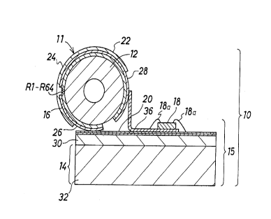
Figure 1 is a cross-sectional view of a thermal head apparatus,
showing a preferred embodiment of the present invention;
Figure 2 is a circuit diagram showing a set of a driving circuit, a
temperature detection circuit and a control circuit for one heat generation
element of the thermal head apparatus of Figure 1; and,
Figures 3(a) to 3(g) are time charts illustrating operation of the
circuit of Figure 2.
Figure 1 is a sectional view showing a structure of a thermal head
apparatus according to a preferred embodiment of the present invention.
Referring to Figure 1, the thermal head apparatus is generally denoted as 10
and includes a thermal head section 11 and a mounting circuit board section
15.
The thermal head section 11 includes a cylindrical core 12 made of an
insulating material such as an alumina ceramic, 64 heat generation elements R1
to R64 arranged in a row parallel to an axial line of the core 12 on an outer
surface of the core 12, and 64 core terminals 16 provided on the outer side of
the heat generation elements R1 to R64 and connected to the heat generation
elements R1 to R64, respectively. The heat generation elements R1 to R64 are
5
each formed from a resistor member whose electric resistance has a high
temperature dependency such as, for example, a thin film of an alumina alloy.
A common electrode 22 is provided at another portion of the outer surface of
the core 12 remote from the portion where the core terminals 16 are provided.
The common electrode 22 is connected to all of the heat generation elements
R1 to R64. All of the heat generation elements R1 to R64 and most of the core
terminals 16 and the common electrode 22 are covered with a protective film
24, and plated solder terminals 26 and 28 are provided at portions of the core
terminals 16 and the common electrode 22 which are not covered with the
protective film 24, respectively.
The mounting circuit board section 15 includes an integrated circuit
18 mounted on a mounting circuit board 14. The integrated circuit 18 includes
driving circuits for individually supplying electric currents to the heat
generation
elements R1 to R64 for a fixed period of time, temperature detection circuits
for
individually detecting the temperatures of the heat generation elements R1 to
R64, and control circuits for individually controlling the heat generation
elements
and the driving circuits. The driving circuits, temperature detection circuits
and
control circuits are provided for the individual heat generation elements R1
to
R64. The mounting circuit board 14 includes a flattened base plate 32 of a
synthetic resin, and an insulator layer 30 made of an insulating material such
as an alumina ceramic and formed on the base plate 32. A number of mounting
circuit board terminals 20 equal to the number of the core terminals 16 are
provided in the same pitch as that of the core terminals 16 on the surface of
the
insulator layer 30. The mounting circuit board terminals 20 are plated with
gold,
and a flexible cable 36 is connected to them. The integrated circuit 18 is
connected to the flexible cable 36 by way of gold wires 18a. The flexible
cable
36 is connected also to an external control circuit section (not shown). It is
to
be noted that such external control circuit section may possibly be
incorporated
alternatively in the thermal head apparatus 10 shown in Figure 1.
Figure 2 shows a set of a driving circuit, a temperature detection
circuit and a control circuit for each one of the heat generation elements.
Such
6
circuit is provided for each of the 64 heat generation elements R1 to R64. In
Figure 2, one heat generation element is shown as a single resistor 208.
Referring to Figure 2, the resistor 208 as one heat generation
element is connected at a terminal thereof to a do power source (not shown)
and connected at the other terminal thereof to the collector of a driving
transistor
206 by way of a fixed resistor 209. Consequently, when the resistor 208 is
turned on, electric current flows through the resistor 208 so that the
resistor 208
generates heat. The electric current then depends almost entirely upon the
resistance value of the resistor 208 and a do voltage VHD applied to the
resistor
208. Further, a voltage obtained by dividing the do voltage VHD between the
resistor 208 and the fixed resistor 209 appears across the resistor 208. This
voltage varies depending upon the temperature of the fixed resistor 209 (when
the temperature of the resistor 208 rises to decrease the resistance value,
the
voltage rises) since the resistance value of the resistor 208 varies depending
upon the temperature, and a detection signal 207 corresponding to the
temperature of the resistor 208 can be extracted from a junction between the
resistor 208 and the fixed resistor 209. Since the junction is connected to
one
of a pair of input terminals of an amplification circuit 210, an amplification
signal
211 obtained by amplification of the detection signal 207 is output from the
amplification circuit 210.
The amplification signal 211 is input to a first comparison circuit
216 and a second comparison circuit 218. In the first comparison circuit 216,
the amplification signal 211 is compared with a reference signal 215 set to a
high threshold value while, in the second comparison circuit 218, the
amplification signal 211 is compared with another reference signal 217 set to
a
low threshold value. An output signal 204 representing a result of the
detection
of the first comparison circuit 216 is output to a first AND gate 202 together
with
a driving signal 201 from the outside, and is output also as a first abnormal
condition notification signal from a first output terminal 219 to the outside.
An
output signal 205 of the first AND gate 202 is input to the base of the
driving
transistor 206 so that the driving transistor 206 is turned on or off in
response
7
to the output signal 205. Meanwhile, an output signal 212 representing a
result
of the comparison of the second comparison circuit 218 is input to a second
AND gate 221 together with a cyclic timing signal 220 from the outside. An
output signal 222 of the second AND gate 221 is output as a second abnormal
condition notification signal from a second output terminal 223 to the
outside.
Operation of the circuit having the construction described above
will be described below with reference to the time charts of Figures 3(a) to
3(g).
It is to be noted that, in the following description, when the signal level in
the
time charts of Figures 3(a) to 3(g) is HIGH, the logical value is "1", and
when
the signal level is LOW, the logical value is "0".
In an initial state, the output signal of the first comparison circuit
216 is "1". Accordingly, when the driving signal 201 from the outside changes
to "1" in the waveform of Figure 3(a), the output of the first AND gate 202
also
changes to "1" and the driving transistor 206 changes from "1" to "0" in the
waveform of Figure 3(b), that is, the driving transistor 206 is turned on.
Consequently, the resistor 208 serving as a heat generation element is
energized to generate heat.
Since the resistor 208 itself serves as a heat generation element
and also as a temperature detection element whose resistance value varies
depending upon the temporature thereof, when the temperature of resistor 208
rises, the voltage of the detection signal 207 rises. Consequently, also the
driving signal 211 output from the amplification circuit 210 as a result of
amplification of the detection signal 207 rises as the temperature of the
resistor
208 rises, as seen from the waveform of Figure 3(c).
When the resistor 208 (heat generation element) generates heat
to raise the temperature thereof gradually in an ordinary operation, where
thermosensitive paper is used, a portion of the thermosensitive paper
corresponding to the resistor 208 develops a color to form a dot.
Alternatively,
in heat transfer printing, ink at a portion of an ink film corresponding to
the
resistor 208 is melted and sticks to the surface of print paper to form a dot.
8
Such heat generation of the resistor 208 comes to an end when
the driving signal 201 from the outside changes from "1" to "0", as seen from
the waveform of Figure 3(a), whereupon also the output of the first AND gate
202 changes from "1" to "0" and the driving transistor 206 is turned off.
If a fine foreign object which obstructs a normal printing operation,
such as a fine metal piece, a hair, a minute stone piece or a fine piece of
paper,
is present on the front surface or the rear surface of, for example,
thermosensitive paper sheet or a thermal transfer ink film, heat from the
resistor
208 is prevented from being transmitted regularly to the thermosensitive paper
or the heat transfer ink film by the foreign object. Consequently, the
temperature of the resistor 208 itself rises rapidly, and the voltage of the
detection signal 207 also rises rapidly. The amplification signal 211 from the
amplification circuit 210, by which the detection signal 207 is amplified, is
input
to the first comparison circuit 216, in which signal 211 is compared with the
reference signal 215 of the high threshold value, as seen from the waveform of
Figure 3(c).
When the amplification signal 211 becomes higher than the
reference signal 215 at the first comparison circuit 216 (time t1), the output
signal 204 of the first comparison circuit 216 changes to "0" (Figure 3(d)).
Consequently, the output signal 205 of the first AND gate 202 changes to "0",
and the driving transistor 206 is turned off. As a result, generation of heat
of
the resistor 208 is stopped. In this instance, the output signal 204 of the
first
comparison circuit 216 is output also to the outside from the first output
terminal
219 so that it is notified to the outside that the resistor (heat generation
element) 208 is an abnormally high temperature condition. Consequently, the
driving signal 201 from the outside will be changed from "1" to "0" and the
driving transistor 206 will continue its off state.
On the other hand, if the characteristic of a particular one of the
64 resistors (heat generation elements) is varied to be different from that of
the
other resistors (heat generation elements) so that the particular heat
generation
element generates a reduced amount of heat, or if a driving circuit for a
_..
9
particular one of the resistors (heat generation elements) 208 is disconnected
so that it does not generate heat any more, then the amplification signal 211
does not exhibit a voltage rise any more as seen from the waveform of Figure
3(e). In this case, the amplification signal 211 is compared with the
reference
signal 217 of the low threshold value from the outside by the second
comparison circuit 218. However, since the amplification signal 211 does not
rise higher than the threshold value, the output signal 212 of the second
comparison circuit 218 exhibits the value "1". The output signal 212 is input
to
one of a pair of input terminals of the second AND gate 221. Since a timing
signal 220 as seen in the waveform of Figure 3(f) is input cyclically from the
outside to the other input terminal of the second AND gate 221, an output
signal
222 as seen in the waveform of Figure 3(g) is output from the second AND gate
221 in synchronism with the thus-input timing signal 220. The output signal
222
is output from the second output terminal 223 t the outside, so that it is
notified
to the outside that the resistor (heat generation element) 208 does not
generate
heat regularly.
It is to be noted that, while the thermal head apparatus in the
embodiment described above is formed as a line head apparatus, wherein the
heat generation elements R1 to R64 are arranged in a row such that they may
operate to print at time on paper along a lateral line perpendicular to the
direction in which the paper is fed, the present invention can be applied also
to
a serial head wherein heat generation elements are arranged in a row parallel
to a paper feeding direction and print while being moved in a lateral
direction
perpendicular to the paper feeding direction.
Having now fully described the invention, it will be apparent to one
of ordinary skill in the art that many changes and modifications can be made
thereto without departing from the spirit and scope of the invention as set
forth
herein.