Note: Descriptions are shown in the official language in which they were submitted.
21~8~6
WO 95132574 PCT/US95/03494
TELEPHONE MOUNTING RECEPTACLE HAVING OPPOSED
RETRACTAB~E ~ATCH MlE~MBERS
Back~round of the Invention
The present invention relates generally to telephone receptacles
and, more particularly, to a telephone mounting receptacle having
retractable latch members eng~ing a portion of a telephone.
Cellular communication systems permit a user to comm-lnicate
telephonically at virtually any location. Bec~ e of this unique
convenience, the number of cellular telephone users has increased
dra~atically in recent years. VVhile many users utilize a mobile
cellular telephone that is permanently mounted within an automobile
("mobile"), other users opt for a portable cellular telephone that is
not restricted for use within the automobile ("portable'l), such as
Mo~orola's DYNA T-A-CTM Cellular Portable Telephone.
While opting for the freedom and versaltility of a portable, a
user often finds it necessary to utilize such telephones while driving
an automobile. Because both eyes and hands must generally be
utilized in order to initi~tP. a call, it is advantageous for the driver of
an automobile to have a conveniently located ]mounting receptacle for
temporarily supporting the portable. Portable users generally prefer
mounting receptacles that can be ~ltili7ed in canjunction with other
"hands free" accessories that effectively allow the portable to
function in a manner ~imil~r to a conventional telephone speaker
phone.
WO 95/32574 PCT/US95/0349~
~6~81 ~ 2
Most of the existing automobile mounting receptacles are
designed to accommodate mobile handsets rather than portable units.
Many mobile handset mounting receptacles, generally referred to as
hang-up cups, are dimensioned to accept the box-like ear piece
S portion of the handset, which is located at one end of the
predomin~ntly longitll-lin~l handset; handsets have a longit-l~in~l
dimension that is substantially longer than the transverse dimension
that is orthogonal to the longitll~lin~l dimension. The ear piece
portion generally contains two molded opposing latching surfaces
10 along the lon~itll-lin~l axis of the handset that fit corresponding
latching members of the hang-up cup. One latching member may be
retractable and permit removal of the handset when an actuation
force is applied to a side button; however, removal of a handset is
generally accomplished by exerting a rotational torque on the handset
15 and pulling it away from the hang-up cup in an up and out fashion;
re-attachment of the handset to the hang-up cup is accomplished by
reversing the previous movement.
Bec~nse the portable does not have a protruding portion with
convenient latching surfaces ~imil~r to the ear piece portion of the
20 mobile handset, previously known hang-up cups could not readily be
utilized to accept the portable. However, because previously known
hang-cups generally latch along the longitllt1in~1 axis of the ear piece
portion, one might try using longit~l-lin~l axial latching for portable
receptacles. To accomplish longitl1~1in~1 latching of opposing ends of
25 the portable, the portable receptacle must, unfortunately, be
fabricated to extend along the entire longitnflin~l length of the
portable, which in turn requires an automobile mounting surface that
corresponds to the lengthy dimensions of the portable.
Because the portable receptacle contacts the entire lon~itllflin~l
30 length of the portable, the user may have difficulty when attempting
to remove the portable from the portable receptacle. Inability to
extend the thumb and forefinger around the perimeter of a portion of
the portable while it is retained in the portable receptacle may not
W095/32574 21~ 5 8 1 6 PCT/US95/03494
3 ~
only hamper removal of the received portable, but also cause the user
to drop the portable during the removal process.
The longitll~lin~l latching must also account for the relatively
heavy weight of the portable in reference to that of the mobile
S h~n-lset. Because strong gravitational forces are imparted on both
the portable and the receptacle while the automobile is moving,
longer latching surfaces extending into corresponding deep molded
housing notches of the portable are required to adequately anchor the
accepted portable. Unfortunately, deep notches impact the already
10 limited space devoted to the portable's internal electrical components.
Also, the lon.~itllrlin~l latching mech~nicm wiill have to place
additional force on the latch-portable contacl: points in order to
ensure retention of the accepted portable while the automobile is
moving. However, the user must then exert additional force when
15 removing the portable from the receptacle Ol inserting the portable
into the receptacle.
Brief Description of the Drawin~s
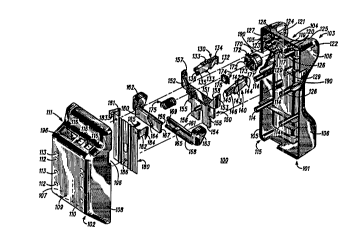
FIG. 1 illustrates an exploded view of the telephone mounting
receptacle according to the present invention;
FIG. 2 illustrates an underside view of the front housing
25 porhon 101 of the telephone mounting receptacle with the assembled
latch mech~ni.sm in a latch position according to the present
invention,
~IG. 3 illustrates a partial underside view of the front housing
30 portion of the telephone mounting receptacle with the assembled
latch mechanism in a release position according to the present
invention, and
_ _ _ _ _ _ _ ~
WO 95/32S74 PCT/US9StO349 1
-
2 3L ~ 6 4
FIG. 4 is a perspective view of the telephone mounting
receptacle and associated telephone according to the present
invention.
Description of a Preferred Embodiments
What is needed is a mounting receptacle for a portable cellular
telephone compatible with "hands free" accessories that latches across
10 the shorter transverse dimension of the portable with a minimum
amount of force, has short latching surfaces that correspond to
shallow latching notches in the telephone and accepts only a portion
of the telephone so as to facilitate handling by the user during
removal of the telephone from the receptacle.
The present invention provides a telephone mounting
receptacle for a cellular telephone that accepts a portion of the
cellular telephone. The portion of the cellular telephone is retained
in the mounting receptacle by facially opposed retractable latch
members partially disposed within the telephone receptacle. The
20 retractable latch members are oriented to latch along the transverse
dimension of the cellular telephone. When the retractable latch
members are positioned in a latch position, the portion of the cellular
telephone may be accepted by the mounting receptacle. While
accepted, a spring element provides an upward force against the
25 bottom face surface of the cellular telephone promoting attachment
between the short latching surfaces of the retractable latch members
and shallow latching notches formed in the cellular telephone.
Removal of the cellular telephone from the mounting receptacle is
accomplished by applying a minim~l actuation force to a force
30 receiving surface coupled to the retractable latch members via an
intermediate actuator element. The actuation force causes
simultaneous movement of retractable latch members to a release
position that in turn causes the spring element to force the cellular
telephone away from the mounting receptacle.
WO 9S/32574 2 1 ~ ~ 8 ~ ~ PCT/USgS/0349~
s
FIG. 1 illustrates an exploded view of' a telephone mounting
receptacle 100 according to the present invention. The telephone
mounting receptacle 100 includes a front housing portion 101 having
a contoured front face surface 103 that interconnects a right outer
side portion lOS and a left outer side portion 106, each having an
opening 190. The front face surface 103 is further defined by a
subst~nti~lly planar recessed area 104 having an opening 117 as well
as a right recessed area side portion 124 and a left recessed area side
portion 125. The substantially planar recessed area 104is
dimensioned to accept a portion of the cellu]ar telephone. The right
recessed area side portion 124 and the left recessed area side portion
125 include respective facially opposed openings 121 and 122. The
opening 117 is located between the facially opposed openings 121
and 122. The front housing portion 101 also includes a rear face
surface 115 having outward-extending molded protrusions that
permit attachment of latch mech~ni~m components and a rear
housing portion 102.
The rear housing portion 102 of the te,lephone mounting
receptacle 100 is box-like and includes a planar rear face surface
109. The planar rear face surface 109 includes a plurality of
depressions, such as depressions 112, having center bores within
extending shaft members which mate with ou.tward extending shaft
members 114 of the rear face surface 115 pe:rmitting attachment of
the front housing portion 101 and the rear housing portion 102. The
planar rear face surface 109 further includes a plurality o
throughholes, such as throughholes 113, whic:h permit attachment of
the telephone mounting receptacle 100 to an automobile mounting
location.
The rear housing portion 102 also incllldes a right side portion
107 and a left side portion 108. The right sid.e portion 107 and the
left side portion 108, each cont~inin~ an opening 196, are formed to
interconnect and extend subst~nti~lly orthogonal to the planar rear
face surface 109. The right side portion 107 and the left side portion
108 are further interconnected by a top side portion 111 and a
WO 95/32574 PCT/US9510349-1
1 6 6
bottom side portion 110. The top side portion 111 extending from
the planar rear face surface 109 in a contoured and stepped manner
includes openings 116 that permit external cabling for "hands free"
circuitry that may reside within the telephone mounting receptacle
100. The bottom side portion 110 extends from the planar rear face
surface 109 at an angle and may include slotted openings so as to
permit the lltili~tion of a "hands free" speaker mounted inside the
telephone mounting receptacle 100.
The telephone mounting receptacle 100 further includes a
right retractable latch member 130 and a left retractable latch
member 140. The right retractable latch member 130 is inserted via
the rear face surface 115 into a cavity 123 formed between an outer
sidewall 105 and the right recessed area side portion 124. A front
portion of the right retractable latch member 130 comprising a short
latching surface 132 resides in the right facially opposed opening 121
upon lnsertion.
A middle portion of the right retractable latch member 130
comprising a pair of vertical axis tabs 133 extending outward from
the top and bottom surface thereof, fit into a pair of corresponding
notches 127 of the rear face surface 115 upon insertion. The pair of
vertical axis tabs 133 allow pivotal movement about an axis such that
movement of a rear portion of the right retractable latch member
130 in one direction causes movement of the front portion of the
right retractable latch member 130 in the opposite direction, or vice
versa. Thus, movement of the rear portion of the right retractable
latch member 130 allows the short latching surface 132 to extend
through or retract into the right facially opposed opening 121.
However, the short latching surface 132 is prevented from
excessively extending through the right facially opposed opening 121
by a plurality of ret~inin~ tabs, such as ret~ininp: tab 134, extending
outward from the top and bottom of the front portion of the right
retractable latch member 130.
The rear portion of the right retractable latch member 130
comprises both a projecting nub 135 extending from the left face
;816
WO 95132574 PCT/US95/0349 1
surface and an angled portion 136 tapering along the bottom right
face surface thereof. Upon assembly of the latch mechanism, the
angled portion 136 will be further coupled to an intermediate
actuator element 150.
The left retractable latch member 140 is preferably an
identical mirror image of the right retractab:le latch member 130 and
includes a mirrored short latching surface 142, a mirrored pair of
vertical axis tabs 143, a mirrored pair of ret~ining tabs 144, a
mirrored projecting nub 145, and a mirrored angled portion 146
also coupled to the intermediate actuator element 150. Formations
integral to the front housing portion 101 permitting accommodation
of the right retractable latch member 130 are preferably mirrored to
permit similar accommodation of the left retractable latch member
140.
The intermediate actuator element 150 is comprised of a ledge
portion 151 residing upon a base portion 154. A right protrusion
152 and left protrusion 153 extend upwardly from the ledge portion
151. The inwardly opposing faces of the right protrusion 152 and
left protrusion 153 are defined by a respective right ramped portion
157 and left ramped portion 158, each extending in an angled
manner from the top face of the ledge portion 151 to the peak of the
respective right protrusion 152 and left protrusion 153. The right
ramped portion 157 and the left ramped portion 158 permit
complementary slidable engagement with the angled portion 136 of
the right retractable latch member 130 and the angled portion 146 of
the left retractable latch member 140, respectively.
The base portion 154 of the intermediate actuator element 150
includes rectangularly slotted openings 155 and a projecting tab 156.
The slotted openings 155 are of dimensions to permit extension of
rectangular tabs 129 extending from the rear face surface 115 of the
front housing portion 101 therell~ough. The rectangularly slotted
openings 155 are vertically elongated to allo~ the intermediate
actuator element 150 to move longihl-lin~lly while abutted against the
rear face surface 115. The projecting tab 156, formed integral with
WO 95/32574 PCT/US95/0349~
i,
216a~1~ g
the interrnediate actuator element 150, projects from the rear face
surface of the base portion 154.
The telephone mounting receptacle 100 further includes
longit~ltlin~lly extending plate members 160 and 161 having tabular
5 end portions 162 and 163, respectively, forming force receiving
surfaces. The plate member 160 includes a slotted opening 164.
Simil~rly, the plate member 161 includes a slotted opening 165.
Formed to extend longit~l-lin~lly along the length of the front surface
of the plate member 160 are a rail member 166 and a track member
167. Simil~rly, but formed to extend longit~lclin~lly along the rear
surface of the plate member 161, are a rail member 168 and a track
member 169.
The plate members 160 and 161 and the rail and the track
members 166 and 169 formed on the front and the rear surfaces,
15 respectively, of the respective plate members are of dimensions to
permit inte~ i"~ engagement therebetween to permit relative
sliding movement between the plate members 160 and 161 when
positioned in a confronting relationship. Similarly, the track
member 167 of the plate member 160 and the rail member 168 of
the plate member 161 are of dimensions to permit intelriLLillg
engagement such that sliding movement between the plate member
160 and 161is permitted when positioned in a confronting
relationship. The slotted openings 164 and 165 are of dimensions to
perrnit extension of the projecting tab 156 of the intermediate
actuator element 150 therethrough.
The telephone mounting receptacle 100 includes an element
170 having a cylindrical body with an enclosed circular front face
surface and an outward extending concentric ledge 171 formed about
the periphery of an opened rear portion 173. Protruding further
from the outward extending concentric ledge 171 are locating tabs
172. The cylindrical element 170 extends through the opening 117
of the subst~nti~lly planar recessed area 104 via the rear face surface
115. The locating tabs 172, which prevent rotation of the cylindrical
element 170, fit into corresponding notched guides 118 contained
WO 95/32574 ~ PCT/US95/0349~
9
within the raised wall extending from the rear face surface 115 and
encircling the periphery of the opening 117. The cylindrical element
170 moves perpendicularly with respect to the plane formed by the
subst~nti~lly planar recessed area 104 and within the confines of the
5 opening 117 and the raised wall 119. Perpendicular retraction of the
cylindrical element 170 into the substantially planar recessed area
104 is further opposed by a spring 175 having a first end disposed
bellind the front face surface of the cylindrical element 170 via the
opened rear portion 173 and a second end retained by a retention
10 panel 180.
An electromechanical switch 174is mounted about the
periphery of the opening 117 on pegs 120 extending from the rear
face surface 115 of the front housing portion 101. The
electromechanical switch 174 includes a lever arm 176 that extends
15 through an opening in the raised wall 119 and contacts the concentric
ledge 171. When no, or insufficient, perpendicular force is applied
to the front face surface of the cylindrical element 170, the lever
arm 176 remains in contact with the concentric ledge 171 and in a
"switched" position. Force applied to the fromt face surface of the
20 cylindrical element 170 retracts the cylindricaLl element 170 c~nsing
the lever arm 176 to be positioned in an "unswitched" position.
Therefore, the electromechanical switch 174 can provide electrical
sign~l.c capable of discrimin~tin~ the state of occupancy of the
substantially planar recessed area 104 to "hands free" electronic
25 circuitry that could be lltili7e-1 in conjunction with the telephone
mounting receptacle 100.
The retention panel 180 provides seating for the second end of
the spring 175 on the front face surface thereof. A plurality of
throughholes, such as throughhole 186, permi~ attachment of the
30 retention panel 180 to threaded shaft members 126 extending from
the rear face surface 115 so as to retain the spring 175, the plate
members 162 and 163, and the intermediate actuator element 150 in
the position thereabove. A curved ret~ining finger 185 extends
outward from the top edge of the retention panel 180 to contact and
WO 95/32574 2 ~ ~ 81 PCT/US95/0349~1
;.~ ` 10
m~int~in the position of the electromechanical switch 174 upon the
pegs 120. The retention panel 180 is preferably tooled from a sheet
of rigid alloy material, such as beryllium-copper, so as to contain
longitll~lin~lly extending corrugations that retard transverse bending
of the retention panel 180.
The retention panel 180 also includes a right rigidly elastic
latch flange 181 and a left rigidly elastic latch flange 182 formed by
folding of material at the top right and left edge of the retention
panel 180. The right rigidly elastic latch flange 181 material is
initially folded into a first portion extending orthogonally from the
plane formed by the retention panel 180. Next, a second portion of
the right rigidly elastic latch flange 181 material is realized by a
second outward reverse fold of the first portion. The resulting right
rigidly elastic latch flange 181 is somewhat "V"-shaped. The face of
the second portion of the right rigidly elastic latch flange 181
includes a bore 183 extending therethrough. Normal forces applied
to the face of the second portion of the right rigidly elastic latch
flange 181 are countered by the elastic spring-like aspect inherent at
the fold which demarcates the first and second portion of the right
rigidly elastic latch flange 181. The left rigidly elastic latch flange
182 having a bore 184 is formed from the left edge material of the
retention panel 180 such that the left rigidly elastic latch flange 182
is preferably an identical mirror image of the right rigidly elastic
latch flange 181.
With attachment of the retention panel 180 to the rear face
surface 115, the right rigidly elastic latch flange 181 extends into the
cavity 123 adjacent to the right retractable latch member 130 such
that the bore 183 permits the projecting nub 135 of the right
retractable latch member 130 to extend therethrough. Likewise, the
left rigidly elastic latch flange 182 extends into a similar cavity area
such that the bore 184 accommodates the projecting nub 145 of the
left retractable latch member 140. The right rigidly elastic latch
flange 181 and left rigidly elastic latch flange 182 exert a
subst~nti~lly normal force upon the rear face portions of the
WO 95/32574 ~ 1 6 5 ~ I 6 PCT/US95/03494
11
respective right retractable latch member 130 and left retractable
lateh member 140 causing abutment of the right angled portion 136
and the left angled portion 146 against the respective right ramped
portion 157 and left ramped portion 158. This causes the right short
latching surface 132 and the left short latching surface 142 to
protrude through the respective facially opposed openings 121 and
122 and assume a latch position.
FIG. 2 illustrates an underside view of the front housing
portion 101 of the telephone mounting receptacle 100 with the
assembled latch mechanism in a latch pOSitiOIl 200 according to the
present invention. A portion of the retention panel 180 has been
cutaway to better illustrate the interrelationship between the
longit-l-lin~lly extending plate members 160 and 161, the
intermediate actuator element 150, the right retractable latch
melmber 130, and the left retractable latch member 140. With the
latch mechanism in the latch position 200, the right retractable latch
member 130 and the left retractable latch melmber 140 are in
position to accept the portion of the telephone into the telephone
mounting receptacle 100.
The longitlldin~lly extending plate members 160 and 161 are
aligned with one another such that the rail member 166 of the plate
member 160 is positioned in an interfitting relationship with the
track member 169 of the plate member 161, and the rail member
168 of the plate member 161 is positioned in an interfitting
relationship with the track member 167 of the plate member 160 to
pernnit sliding engagement therebetween. The end portions of plate
members 160 and 161 respectively extend through the openings 190
such that the force receiving surfaces 162 and 163 project beyond the
surfaces of the respective outer sidewalls 105 and 106. The
projecting tab 156 formed to extend from the base portion 154 of the
intermediate actuator element 150 extends through the slotted
opening 165 of the plate member 161, and the slotted opening 164 of
the plate member 160.
W0 95/32574 ~ 8 1 ~ 12 PCT/US95/0349~1
An actuation force applied to either the force receivin~ surface
162 in the direction illustrated by an arrow 290, or upon the force
receiving surface 163 in the direction illustrated by an arrow 291
causes translation of the respective plate members 160 and 161.
5 Translation of the plate members 160 and 161, responsive to
actuation forces applied to either or both of the force receiving
surfaces 162 and 163, exerts forces upon the projecting tab 156
projecting from the base portion 154 of the intermediate actuator
element 150. Because the slotted openings 164 and 165 extend at
10 angles relative to the direction of tr~n.~l~tion permitted of the plate
members 160 and 161, a component force transmitted to the
projecting tab 156 causes tr~n~l~tion of the intermediate actuator
element 150 in the direction illustrated by an arrow 293.
As the intermediate actuator element 150 tr~n~l~tes in the
15 direction illustrated by the arrow 293, the right angled portion 136
and the left angled portion 146 slidably coupled to the right ramped
portion 157 and the left ramped portion 158, move in the direction
illustrated by the arrows 290 and 291, respectively. This tr~n~l~tion
causes compression of the right rigidly elastic latch flange 181 and
20 the left rigidly elastic latch flange 182 coupled to ~he projecting tabs
135 and 145 of the respective right retractable latch member 130 and
left retractable latch member 140. The right retractable latch
member 130 and left retractable latch member 140 simultaneously
pivot about their respective pair of vertical axis tabs 133 and 143
25 c~l~sin~; their respective short latching surfaces 132 and 142 to move
in the direction illustrated by respective arrows 292 and 294. The
tr~n~l~tion of the latch mech~ni~m in the aforementioned manner
results in a release position as illustrated in FIG. 3.
F~G. 3 illustrates a partial underside view of the front housing
30 portion 101 of the telephone mounting receptacle 100 with the
assembled latch mech~ni~m in the release position 300 according to
the present invention. A portion of the retention panel 180 has been
cutaway to better illustrate the interrelationship between the
longitll-lin~lly extending plate members 160 and 161, the
WO 95/32574 2 ~L 6 ~ PCT/US95/03494
-
13
interrnediate actuator element 150, the right retractable latch
member 130, and the left retractable latch member 140. With the
latch mechanism in the release position 300, the right retractable
latch member 130 and the left retractable latch member 140 are in
S position to release the telephone from the telephone mounting
receptacle 100.
When no actuation force is applied to ,any of the force
receiving surfaces 162 and 163, the elastic spring force exerted by
the joints of the right rigidly elastic latch flange 181 and the left
rigidly elastic latch flange 182 of the retention panel 180 causes a
reverse tr~n.~l~tion. The rear portions of both the right retractable
latch member 130 and left retractable latch member 140 that are
coupled to the respective right rigidly elastic latch flange 181 and
left rigidly elastic latch flange 182 are forced to pivot about their
respective pair of vertical axis tabs 133 and 143 in the directions
illustrated by a,rrows 292 and 294, respective.ly. This in turn causes
the respective short latching surfaces 132 and 142 to simultaneously
move in the direction of the arrows 292 and 294, respectively. As
the rear portions of the right retractable latch member 130 and the
left retractable latch member 140 pivot in the directions illustrated
by arrows 292 and 294, respectively, a component force causes the
slidably coupled right ramped portion 157 and left ramped portion
15~ to move in a direction opposite to that illlustrated by the arrow
293. The intermediate actuator element 150 a,nd the projecting tab
156 further cause the plate members 160 and 161 to tr~n.~l~te in the
direction of the arrows 292 and 294, respectively. This results in the
latch position illustrated by FIG. 2.
F~G. 4 depicts a perspective view of the telephone mounting
receptacle 100 and an associated telephone 400. The telephone 400
has a longit~ltlin~l dimension and a transverse ~imension orthogonal
to the lon~:it~ n~l dimension, the longit~l~lin~l dimension being
longer than the transverse dimension. The telephone 400 preferably
comprises a lon,~itll~lin~l dimension of approxinl~tely 19.5 cm and a
transverse dimension of approximately 4.4 cm., The telephone 400 is
WO 9S/32574 PCT/US9~/0349~
2 ~ 6 ~ 14 ~
housed within a housing formed of a top housing portion 401 and a
bottom housing portion 402. A battery 406 extends along the entire
lonp~itll~lin~l and transverse dimension of the telephone 400 and
occupies the bottom surface of the telephone 400.
The short latching surfaces 132 and 142 of the respective right
retractable latch member 130 and left retractable latch member 140
extend in a facially opposed manner above the substantially planar
recessed area 104. The short latching surfaces 132 and 142 are
molded so as to fit corresponding shallow front notches 404 (only a
right side notch is shown) formed into both the right and left sides of
the top housing portion 401 of telephone 400. The corresponding
shallow front notches 404 could also be formed on the bottom
housing portion 402. Furthermore, the seam defined by the
boundary of the top housing portion 401 and the bottom 402 housing
portions could also accommodate the short latching surfaces 132 and
142.
The telephone mounting receptacle 100 also includes a left
short toe prong 440 and a right short toe prong 450 capable of
additionally securing a portion of the telephone within the
subst~nti~lly planar recessed area 104. The left short toe prong 440
and right short toe prong 450 extend in a facially opposed manner
above the subst~nti~lly planar recessed area 104 and are molded to fit
corresponding shallow rear notches 405 (only a right side notch is
shown) formed into both the right and left sides of the top housing
portion 401. The corresponding shallow rear notches 405 could also
be formed on the bottom housing portion 402. Furthermore, the
seam defined by the boundary of the top housing portion 401 and the
bottom housing portion 402 could also accommodate the left short
toe prong 440 and the right short toe prong 450.
A user may engage the telephone 400 into the telephone
mounting receptacle 100 in the following manner. The telephone
400 must initially be slightly angled with respect to the subst~nti~lly
planar recessed area 104 so that the shallow rear notches 405 are
positioned to engage the corresponding left short toe prong 440 and
WO 9~i/325'74 2 ~ 1 6 PCT/US95/03494
15
the right short toe prong 450. The telephone 400 is then positioned
so that the bottom face surface of the battery 406 becomes
substantially parallel to the subst~nti~lly pla~ar recessed area 104
causing the shallow rear notches 405 to engage the left short toe
S prong 440 and right short toe prong 450, causing the cylindrical
element 170 to become depressed, and causirlg the shallow front
notches 404 to engage the short latching surfaces 132 and 142 of the
respective right retractable latch member 130 and left retractable
latch member 140.
While the telephone 400 is being engaged into the telephone
mounting receptacle 100, the bottom face surface of the battery 406
exerts a normal force on the face surface of the cylindrical element
170 causing the retraction of the cylindrical element 170 into the
substantially planar recessed area 104. Because the cylindrical
1~ butl:on 170 is located between the right retractable latch member 130
and the left retractable latch member 140, the upward force exerted
by the spring-loaded cylindrical button 170 promotes contact
bet~,veen the short latching surfaces 132 and 142 of the respective
right retractable latch member 130 and left retractable latch member
20 140 and the corresponding shallow front notches 404. This permits
adequate latching and retention of the telephone 400 without
requiring long latching surfaces and deep corresponding front
notches.
Because the telephone mounting receptacle 100 latches the
25 transverse dimension of the telephone 400 subst~nti~lly close to the
center of the longitllclin~l dimension of the telephone 400, less
holding force is required to m~int~in adequate engagement of the
telephone 400. For passenger safety, the United States government
encourages a holding force of at least twenty times the force of
30 gravity for a mounting receptacle installed in an automobile. To
meet these requirements, previously known receptacles latching the
ends of the telephone 400 along the longihl~lin~l axis and away from
the center of gravity, must likely employ an excessively forceful
l~tchin~ mech~ni~m difficult for the user to manually engage or
WO 95/32574 PCT/US9510349 1
21 ~lG 16 ~
disengage. The geometry of the telephone mounting receptacle 100
permits the transversely-oriented short latching surfaces 132 and 142
to be in close proximity to the center of gravity of the telephone 400
so that the required holding force can be accomplished with a less
S forceful mechanism that is easy to engage or disengage.
The substantially planar recessed area 104 is dimensioned to
correspond to the entire transverse dimension of the telephone 400,
but only a portion of the longitll-lin~l dimension of the telephone
400. Thus, after engagement of the telephone 400 into the telephone
10 mounting receptacle 100, approximately one-third of the longit~l-lin~l
dimension of the telephone 400 will extend beyond the subst~nti~lly
planar recessed area 104. This allows the user to enclose the thumb
and index finger around the perimeter of the open one-third of the
telephone 400 while middle fingers are free to apply a force to the
15 force receiving surface 162 to disengage the telephone 400 from the
telephone mounting receptacle 100.
Disengagement of the telephone 400 is accomplished by
applying a force to the force receiving surface 162 of the plate
member 160 extending through the openings 190 and 196 in the
20 right side portions 105 and 107 of the telephone mounting receptacle
100. This in turn causes simultaneous retraction of the short latching
surfaces 132 and 142 of the respective right retractable latch
member 130 and left retractable latch member 140 to a release
position, which impels the spring-loaded cylindrical element 170 to
25 disengage the bottom face surface of the battery 406 away from the
subst~nti~lly planar recessed area 104. Removal of the previously
applied force causes the short latching surfaces 132 and 142 to
reposition in the latch position. After disengagement, the bottom
face surface of the battery 406 rests on the cylindrical element 170
30 such that the shallow front notches 304 rest above the short latching
surfaces 132 and 142 avoiding unwanted re-engagement of the
telephone 400 into the telephone mounting receptacle 100.
In sllmm~ry, the present invention provides a telephone
mounting receptacle for a cellular telephone that is compatible with
WO 9S/32~74 2~ g ~ ~ PCT/US95103494
-
17
"hands free" accessories. The mounting receptacle employs opposing
retractable latch members that extend through openings in the
mounting receptacle and latch the sides of the cellular telephone
along the transverse dimension rather than the longitu~lin~l ends of
5 the cellular telephone; thus, allowing for an optimal but less forceful
latching mech~ni~m. When the retractable latch members are
positioned in a latch position, a portion of the longitllAin~lly
extending cellular telephone may be accepted by the mounting
receptacle. While accepted, a spring-like element provides an
10 upward force against the bottom surface of the cellular telephone
facilitating attachment between the retractable latch members and
notches formed in the cellular telephone; this applied spring force
allows the notches formed in the cellular telephone to be shallow.
The mounting receptacle further comprises an intermediate actuator
15 element coupled between the retractable latch :members and two side
positioned force receiving surfaces. An applic ation of force to either
force receiving surface tr~n.cl~tes the intermediate actuator member
which simultaneously moves the opposing retractable latch members
to a release position allowing the spring element to "eject" the
20 cellular telephone from the mounting receptacle and into the hand of
the user. Because the mounting receptacle only extends along a
portion of the longitll-lin~l length of the cellular telephone, the user is
able ~o assuredly grasp and release the cellular ltelephone with one
hand.