Note: Descriptions are shown in the official language in which they were submitted.
`- 2 1 65872
POWER SYSTEM STABILIZING APPARATUS
The present invention relates to a power system
stabilizing apparatus for improving the capacity of power
transmission of an existing power system, especially one in
which a power electronics technique is applied.
Recently, the electric power demand has increased, but
the constraints to the locations of power sources and the
laying of a transmission line system become more severe. The
power that can be transmitted by a transmission line system
depends on the stability of the system, and its value may be
as small as a half or one third of the power transmission
limit as determined from the heat capacity of the system.
Mainly in Europe and USA a power electronics technique has
been tried to transmit power corresponding to the full heat
capacity of the system. If such a try succeeds, the
transmission ability of a transmission line system is improved
without laying a new transmission line. For example, since
the inductance of a long distance line is large, the limit of
the static power transmission is determined by the impedance
of the transmission line. As one counter-measure to the large
inductance, a series capacitor compensation method in which a
power capacitor is serially inserted in the transmission line
has been adopted to reduce the inductance and the apparent
length of the transmission line. However, if a power
capacitor is inserted, an electrical serial resonance
phenomenon may be caused by the combination of the capacitance
of the inserted capacitor and the inductance. And, if the
resonance frequency comes near to the mechanical
characteristic frequency of a generator-turbine system, axis
torsion of the generator-turbine system can be caused.
Especially, if a large capacitance is provided by the series
capacitor, axis torsion is very likely to be caused, since the
resonance frequency becomes lower and comes near the
mechanical characteristic frequency of the generator-turbine
systemO That is, if a capacitor of large capacitance is
provided in a transmission line for increasing the power
`- 2 1 65872
transmission capacity of the line, the probability of axis
torsion occurrence increases. Several cases have been
reported in which a series capacitor of small capacitance was
used, or a series capacitor was used with some counter-actions
to the problem. Further, a case of abandoning the use of a
series capacitor has also been reported.
With the recent realization of a power semiconductor of a
large power capacity, the high speed switching of a power
component becomes possible by using such a power
semiconductor. For example, it has been tried that the
equivalent capacitance of a power capacitor is changed by
connecting a reactor and a thyristor in parallel with the
capacitor and controlling the current flowing in the reactor.
Since such a composition can change the electrical resonance
frequency, it is possible to prevent axis torsion. If axis
torsion of a generator-turbine system can be prevented, the
power transmission capacity can be increased without laying a
new transmission line, since the inductance of the
transmission line system can be compensated for by using a
series capacitor of large capacitance.
Representing the voltage at the sending end by Vs, the
voltage at the receiving end by Vr, the impedance of the
transmission line system by X and the phase difference between
the voltages of the sending and receiving ends by ~, the
transmitted power P in the system is expressed by the
following known equation.
Vs Vr sin ~ (1)
X
Increasing the transmitted power in the system means
increasing P of the above equation. In the above-mentioned
series capacitor compensation method, the transmitted power
is increased by decreasing X of the above equation. The
following other methods have been devised, i.e. controlling
the effective power P itself, controlling Vs and Vr, and
controlling ~. For example, a braking resistor can be used
- 21 65872
~ .
for controlling the effective power P, a reactive power
compensating apparatus for controlling Vr and Vs, and a phase
shifter for controlling ~. High speed operations of the
equipment can be realized by applying the power electronics
technique to the equipment, but where and how to utilize such
equipment has not been clearly disclosed as yet.
The present invention provides a power system stabilizing
apparatus capable of stabilizing a power system and
suppressing power swings in the system, by installing a
stabilizing unit including a semiconductor switch in a manner
adequate to the operational characteristics and the function
of the stabilizing unit in the power system, and by
controlling the semiconductor switch, based on a system
stabilizing command signal generated by using the detected
values of the power system, in order to improve the
transmission ability of the system in which a plurality of
power plants, load systems, and other transmission components
are operationally connected.
An object of the present invention is to increase the
power transmission capacity of a power system in which a
plurality of power plants, load systems, and other
transmission components are operationally connected.
To attain this object, the present invention provides
a power system stabilizing apparatus provided in a power
system in which generators are connected to load systems,
comprising: a semiconductor switch used for stabilizing said
system; and means for controlling said semiconductor switch to
stabilize power swings of said system corresponding to the
operational states of the system.
In the drawings
Fig. 1 shows an embodiment of the present invention
wherein an energy control type stabilizing unit is used.
Fig. 2 shows an embodiment of the present invention
wherein an energy control type stabilizing unit is applied to
a power system including a plurality of generators.
Fig. 3 is a figure for explaining operations of the
system stabilizing apparatus.
- 21 65872
-
Fig. 4 shows an embodiment of the present invention
wherein a voltage control type stabilizing unit is used.
Fig. 5 shows an embodiment of the present invention
wherein a voltage control type stabilizing unit is used and
controlled by using voltage signals of load systems.
Fig. 6 shows an embodiment of the present invention
wherein an energy control type stabilizing unit is used and
controlled by using voltage signals of a load system and the
sending end.
Fig. 7 shows an embodiment of the present invention
wherein impedance or phase control type stabilizing units are
applied to a power system including a plurality of generators
and transmission lines.
Fig. 8 shows another embodiment of the present invention
wherein impedance or phase control type stabilizing units are
applied to a power system including a plurality of generators
and transmission lines.
Fig. 9 shows an embodiment of the present invention
wherein an impedance or phase control type stabilizing unit is
applied to a power system including a plurality of generators
and a transmission line.
Fig. 10 shows an example of a composition of the
impedance control type stabilizing unit.
Fig. 11 shows an example of a composition of the phase
control type stabilizing unit.
Fig. 12 is an embodiment of the present invention wherein
plural types of system stabilizing units are used.
Fig. 13 is a further embodiment of the present invention
wherein impedance or phase control type stabilizing units are
applied to a power system including a plurality of generators
and transmission lines.
Fig. 14 is a figure for explaining operations of the
system stabilizing apparatus.
Fig. 1 shows a case wherein an energy control type of
system stabilizing unit is installed in a system sending power
generated in a power plant to a load via a transmission line
- 21 6~872
system. Components or circuits shown by the numerals in
Fig. 1 are as follows: The numeral 10 indicates a generator,
the numeral 20 a voltage increase transformer, the numerals 31
and 32 transmission lines for sending the power to a load
5 system 40 including generators, and the numeral 50 a variable
speed fly-wheel generator used as an energy control type of
system stabilizing unit, being composed of a transformer 51
for connecting the variable speed fly-wheel generator to the
power system, a generator 52 for variable speed operations,
a fly-wheel 521 of the generator, a transformer 53 feeding
current for alternatingly exciting a field coil 54 for the
rotor of the generator, and a cycloconverter 542 for
converting the frequency of commercial power to the different
frequency of the current for alternatingly exciting the field
15 coil. The numeral 541 indicates a control circuit for
controlling the cycloconverter 542, the numeral 101 is a pilot
generator for detecting the rotational speed of the generator,
and the numeral 102 is an acceleration detecting circuit for
obtaining the acceleration/deceleration of the speed of the
20 generator based on its detected rotational speed.
Operation of the control unit is explained by Fig. 3.
In Fig. 3, the changes of the alternating voltage Vac of the
sending end of the power plant in the event of a ground fault
occurrence in the transmission line 31 or 32, the changes of
25 the generator output power Pg, the changes of the power
accumulation/discharge signal A/D, and the changes of the
reactive power control signal Q, are shown. Since the voltage
of the sending end of the power plant is 0 during a ground
fault period Tf, the generator output power also becomes 0.
Then, since the mechanical input power becomes larger than the
electrical output power in the generator, the rotational speed
of the generator is accelerated. If the ground fault is
removed, the alternating voltage is recovered in accordance
with the power system characteristics. Since the output power
35 of the generator is also recovered if the alternating voltage
is recovered, the energy accumulated in the generator during
21 65872
the ground fault period is discharged and the generator output
power settles to a new steady oscillating level, if the system
keeps its stability.
In such a case, the variable speed fly-wheel generator
can improve the transient stability of the power system, by
receiving energy from the power system during acceleration
of the generator and by discharging energy to the system
during deceleration of the generator. In the embodiment shown
by Fig. 1, the pilot generator 101 and the acceleration
detecting circuit 102 are provided. The pilot generator
outputs a voltage proportional to the rotational number of the
generator 10, and the acceleration detecting circuit
differentiates the output voltage with respect to time. From
the differentiated value, the changes of the energy
accumulation/discharge signal A/D are obtained as shown in
Fig. 3. When the signal A/D is positive, that is, the
generator is accelerated, the variable speed fly-wheel
generator receives energy from the generator, and when the
signal A/D is negative, that is, the generator is decelerated,
the fly-wheel generator discharges energy to the generator.
The fly-wheel generator is operated so as to receive or
discharge energy, based on the signal A/D. The operations
are achieved by controlling the ignition angle of the
cycloconverter 542. If the phase of the output alternating
voltage of the variable speed fly-wheel generator is advanced
from the phase of the voltage of the power system by
increasing the frequency of the alternating excitation voltage
for the cycloconverter, energy flows from the fly-wheel
generator to the power system, and vice versa.
Although the on-off operations of the variable
speed fly-wheel generator is explained above for
receiving/discharging the energy, it is possible to change
the received or discharged energy of the fly-wheel generator
continuously in proportion to the differential value detected
by the acceleration detecting circuit 102. Then, the
cycloconverter is applied for the alternating excitation
21 65872
-
of the variable speed fly-wheel generator in the above
explanation. Further, an inverter composed of a power device
such as a GTO (Gate Turn-off Thyristor) having the self-
extinction function, an IGBT (Insulated Gate-turn-off
Bipolar Transistor), etc., is also available for the
alternating excitation of the fly-wheel generator. The pilot
generator 101 used as the acceleration detecting circuit of
the generator is then provided at the axis of the generator,
since the power system stabilizing apparatus is installed near
the generator. Although it is possible to detect the
acceleration of the generator by using a detected voltage or
current of an alternating current bus, such a detection method
has the problem that, in an accident in the power system,
since the waveforms of the alternating voltage or current are
distorted, the acceleration of the generator is not correctly
measured, besides a problem of the S/N ratio. In the
embodiment, since the stabilizing apparatus is installed at or
near the power plant, it is also possible to detect the
acceleration of the generator by using a photo-sensor for
detecting the rotational number of the generator. This
method, as well as the method using a pilotconverter, does not
have the problem of the S/N ratio or the problem of incorrect
measurement in the event of an accident in the power system.
Although the apparatus shown in Fig. 1 stabilizes the
power system by energy (effective power) control, it is
possible to realize more effective stabilization of the
system by using a stabilizing unit that controls the reactive
power as well as the effective power, for example, the
above-mentioned fly-wheel generator or a superconductive
magnetic energy storage facility (SMES) that can control both
the effective and reactive power. In the control method of
both the effective and reactive power, the alternating voltage
Vac shown in Fig. 3 is held to a constant value by controlling
the reactive power. That is, when the stabilizing unit
discharges energy to the power system, since the voltage of
the power system rises, the stabilizing unit decreases the
voltage of the power system by discharging the lagging
- 2 1 65872
.
reactive power, and, when the stabilizing unit absorbs energy
from the power system, since the voltage of the power system
falls, the stabilizing unit increases the voltage of the power
system by discharging the leading reactive power. By this
method, it is possible to stabilize the power system better.
As mentioned above, in the event of an accident, since
the power system can be stably operated by a stabilizing
apparatus in which the energy control type of stabilizing unit
is used and installed at the sending end of the power plant,
it is possible to increase the usual transmitted power.
Further, by applying the power electronics technique to a
power system stabilizing apparatus, the stabilizing apparatus
can be operated immediately or in a short time if the
alternating voltage is recovered upon removal of the fault.
That is, in the event of an accident, the time required from
fault detection to its removal by a circuit breaker is at most
an interval of 4 cycles, whereas the apparatus to which the
power electronics technique is applied can be started within
about 3 cycles during a fault, since the operation of a
mechanical component is not necessary in such an apparatus.
Therefore, this apparatus can operate the power system more
stably than stabilizing apparatus using a conventional device,
such as a mechanical type circuit breaker, in which case it
takes an interval of about 6 cycles to start the stabilizing
apparatus.
The signals used for controlling the stabilizing
apparatus are signals of the values of the power plants, load
systems, etc., i.e., voltage, current, power, phase angle,
angular speed, and frequency, and the differential quantities
of those values.
The reason why stabilizing apparatus using the energy
control type of stabilizing unit is adequate in the power
transmitting system shown in Fig. 1 is that a stabilizing
apparatus using an energy control type of stabilizing unit has
the function of absorbing/discharging the energy of the
generator, which is needed to prevent system instability
21 65872
,.
g
caused by the interruption of energy flow from the generator
in the event of a fault on the transmission line through which
the power from the generator is transmitted to the load
systems.
In the energy control type of stabilizing unit to which
the power electronics technique is applied, besides the
variable speed fly-wheel generator, there is a braking
resistor controlled by semiconductors devices, and a
superconduction magnetic energy storage facility (SMES), etc.
Although the braking resistor can absorb but not discharge
energy, it is still effective for stabilizing the power
system.
Although the stabilizing apparatus can be connected to
the output terminal of the generator, it is preferable that
the stabilizing apparatus be connected to the alternating
current bus at the sending end, since receiving/discharging
the energy can be carried out by one stabilizing apparatus
even when there are a plurality of generators in the power
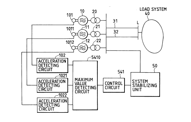
plant. An example of such a case is shown in Fig. 2. The
numerals not shown in Fig. 1 but in Fig. 2 are explained as
follows. The numerals 11 and 12 indicate generators, numerals
21 and 22 are voltage step-up transformers, and the numerals
1011 and 1012 are pulse generators, each for detecting the
rotational speed of the generators 11 and 12. Numerals 1021
and 1022 indicate acceleration detecting circuits, each of
them detecting the acceleration of one of the generators
11 and 12 by using the detected rotational speed, and the
numeral 5410 is a circuit for detecting the maximum absolute
value of the detected acceleration values. The operation of
this embodiment is almost the same as that of the embodiment
of Fig. 1, but different in that the receiving/discharging of
the energy is controlled based on the maximum absolute value
of the detected accelerations of the plurality of generators.
That is, the energy is absorbed by the stabilizing apparatus,
corresponding to the generator indicating the maximum
acceleration, and the energy is discharged by the stabilizing
apparatus, corresponding to the generator indicating the
21 65872
..
maximum absolute value of deceleration. In this way, a power
system including a plurality of generators can be stabilized
by one stabilizing apparatus. The reason why the energy is
absorbed or discharged corresponding to the generator having
the largest absolute value of acceleration or deceleration is
that the stability of the system is determined by the
operation of the generator having the maximum phase shift,
namely, the largest absolute value of acceleration or
deceleration. Since a generator of small power capacity
operates in accordance with a generator of large power
capacity, although generally a generator of small capacity
indicates the maximum absolute value of acceleration or
deceleration, such control is adequate for a system including
a plurality of generators having the same power capacity.
The usual transmission power capacity is generally
determined by the transient stability of the transmission line
system, and the maximum power to be transmitted by the system
is determined by its static stability. Therefore, if it is
intended that the transmissed power be increased to the
maximum power determined by the static stability, the power
capacity required for the stabilizing apparatus is equal to
the difference between the capacity determined by the static
stability and the capacity determined by the transient
stability. Generally, if it is intended to increase the
transmissed power by applying a stabilizing apparatus, the
stabilizing apparatus needs to have a power capacity more than
the capacity to be increased.
Another embodiment is shown in Fig. 4, wherein load
systems including power sources are connected by a
transmission line system, and a static type var compensating
unit is installed at a connecting point as the voltage control
type of stabilizing unit for stabilizing the system voltage.
Numerals 41 and 42 indicate load systems including power
sources, numerals 33 and 34 are transmission lines, and
numeral 60 is a static type of var compensating unit (SVC),
as an example of a voltage control type of stabilizing unit.
Unit 60 consists of a power capacitor 61 for receiving the
- 21 65872
-
11
leading power from the system and a thyristor inverter 62 for
controlling the current flowing in a reactor 63 for receiving
the lagging power from the system. Numeral 601 indicates a
voltage transformer for detecting the voltage of the load
5 system connecting point L, numeral 602 is a control command
generating circuit for generating an ignition command for the
thyristor inverter 62, which commands the increase of a
current in the reactor 63 if the detected voltage is higher
and otherwise a decrease of the current, on the basis of a
judgment whether the detected voltage at the connection
point L is higher than the prescribed value or not. Numeral
603 is a pulse control circuit for controlling the thyristor
inverter.
The operation of this embodiment is explained by
15 referring to Fig. 14. Supposing that a ground fault occurs in
the transmission line 33 or 34 and that Vac indicates the
voltage of the connection point L, the circuit 602 generates
such a control command that the leading reactive power is
received by the stabilizing unit if Vac is higher than the
20 prescribed level expressed by the dash line in the figure, or
otherwise the lagging reactive power is received. An example
of a control command signal is shown by a reactive power
control signal Q in Fig. 14. Positive values of Q expresses
control for receiving the leading reactive power, and negative
25 values of Q control for receiving the lagging reactive power.
The control for receiving the leading or lagging reactive
power is executed by adjusting the current flowing in the
reactor by controlling the ignition angle of the thyristor
inverter. That is, in generating the leading reactive power,
30 the ignition angle is delayed to decrease the current of the
reactor 63, and vice versa. Then, the reactive power is
adjusted by such a sudden control as shown by the change of Q
in Fig. 14. Further, of course, it is possible to control the
reactive power in proportion to the difference between the
35 system voltage and the prescribed level. Then, since the
system stability is improved by the above-mentioned control of
the reactive power, the usual transmissed power of the
21 65872
-
12
transmission lines 33 and 34 can be increased. Further, by
applying the power electronics technique to a power system
stabilizing apparatus, the apparatus can be operated
immediately or in a short time (for example, within 3 cycles)
if the alternating voltage recovers after removal of the
fault. Therefore, this apparatus can operate the power system
more stably than a stabilizing apparatus using a conventional
device such as a mechanical type of circuit breaker in which
it takes 6 cycles to start the stabilizing apparatus.
The reason why the voltage control type of stabilizing
unit is effective for stabilization of the power system in the
embodiment of Fig. 4 is that a loss of synchronism due to the
interruption of the energy flow from the generator, which
occurs in the system shown in Fig. 1, does not occur in the
system shown in Fig. 4, since the two load systems connected
to each other by the transmission line system are stabilized
by controlling the voltage of the transmission lines to keep a
constant value.
As a voltage control type of stabilizing unit to which
the power electronics technique is applied, besides the
above-mentioned SVC, there are a self-excited var compensation
generator (SVG), or a thyristor control parallel capacitor
(TSC), etc.
In Fig. 5, a modification of the embodiment in Fig. 4
is shown. Although the system stabilizing unit 60 is
connected to the alternating current bus to which the load
system 42 is connected in Fig. 4, the system stabilizing unit
is connected to the alternating current bus of the other load
system 41, and an input signal used for generating the control
signal is obtained from the alternating current bus of the
load system 42 (the load system connection point) in Fig. 5.
The operation of this embodiment is the same as the operation
of the embodiment of Fig. 4. The effect of the voltage
control in this embodiment is lower than the embodiment shown
in Fig. 4, since the voltage of the load system is controlled
via the transmission lines 33 and 34. This embodiment is
suitable for a case where enough space to install the
21 65872
-
13
stabilizing unit 60 at the alternating current bus of the
load system 42 is unavailable, or a case where it is intended
to use the stabilizing unit for also stabilizing the load
system 41. For the latter case, the stabilizing unit is
5 controlled by using a signal sent from the load system 41.
The numerals shown in Fig. 5, except the ones in Fig. 4, are
explained as follows. Numeral 621 indicates a voltage
transformer for detecting the voltage of the alternating
current bus of the load system 41 (the voltage at the load
system connection point), numeral 624 is a control command
generating circuit for generating an ignition command to keep
the voltage at the load system connection point within the
prescribed voltage range, on the basis of a judgment whether
the detected voltage is higher than the prescribed level or
15 not, and numeral 604 is a switching circuit which selects
one of the two output signals from the command generating
circuits 602 and 624 as an input signal to the pulse control
circuit 603 in accordance with a signal S from a commanding
circuit not shown in the figure. The operation of this
20 embodiment is the same as that of the embodiment of Fig. 4,
except that an input signal different from the one used in the
embodiment of Fig. 4 is input to each control command
generating circuit. By this embodiment, the voltage values in
both of the load systems 41 and 42 can be stabilized. By
25 using a stabilizing unit also having the voltage control
function as well as the energy control function, for example,
a fly-wheel generator that can control the effective power
(energy) and the reactive power (voltage) in the power
transmission system of the embodiment shown in Fig. 5, the
30 voltage of the load systems can also be controlled and
stabilized. Since, generally, such a system stabilizing unit
can control the effective power and the reactive power
separately, the effective power is controlled by adopting the
system of Fig. 1, and the reactive power is further controlled
35 by the voltage signal of the load system as shown in Fig. 4.
Such an example is shown in Fig. 6. In this figure, a
cycloconverter control circuit 551 uses the output signal of
21 65872
-
14
the acceleration detecting circuit 102 as a signal for
controlling the absorption/discharge of the effective power,
and provides a pulse signal for controlling the reactive power
by using the output signal of the voltage control circuit
5 (or a reactive power control circuit), obtained based on the
difference between the output signal of the voltage
transformer 601 and the prescribed voltage level Vp, which is
input to a cycloconverter 542. In this embodiment, the
cycloconverter is a replacement for the GTO inverter.
Another embodiment is shown in Fig. 7. In this
embodiment, the impedance control and/or voltage control type
of system stabilizing units are serially connected in the
transmission lines, in a system in which the energy generated
by a plurality of generators is sent to a load system via a
plurality of transmission lines. In the figure, numerals 11,
12 and 13 indicate a plurality of generators, numerals 21,
22 and 23 are voltage step-up transformers, numerals 35, 36
and 37 are a plurality of transmission lines, numeral 40 is a
load system including power sources, numeral 71 is an
impedance control type (or phase control type) of system
stabilizing unit, numeral 72 is another impedance control
type (or phase control type) of system stabilizing unit.
Numeral 73 is a voltage transformer for detecting the voltage
of a bus to which the plurality of generators are connected,
numerals 711 and 721 are current transformers, each of which
detects the current of one of the transmission lines
36 and 37, numerals 712 and 722 are control command generating
circuits for obtaining the power flowing in the transmission
lines 36 and 37 and preparing the control commands to suppress
the power swings and settle the power to the prescribed level,
respectively, and numerals 713 and 723 are control units for
respectively outputting control pulse signals based on the
control commands.
The operation of this embodiment is as follows. The
electric energy of the three generators connected to a common
bus at the sending end is transmitted to the load system 40
21 65872
-
via a common bus L connected to the load system. Since the
three transmission lines are connected to both the sending and
receiving ends, the transmitted power flows in each
transmission line according to its impedance. In a system in
which the power of each generator is transmitted to a load
system by one transmission line, the power cannot be
transmitted if a fault occurs in this line. On the other
hand, in this embodiment, a fault in one or two of the
transmission lines does not prevent power transmission, since
the power can be transmitted in the remaining sound
transmission line or lines by removing the line in which a
fault has occurred, which improve the reliability of
transmission.
In such a system, it is supposed that the impedance of
the transmission line 35 becomes lower than that of the other
transmission lines due to some disturbance. Since the
transmitted power then flows mainly in the line 35, this line
goes into an overload state. In this situation, if the
stabilizing units 71 and 72 are of the impedance control type,
they operate to decrease the impedances of the transmission
lines 36 and 37 when they receive the command to increase the
power in each of the lines. As is clear from Eq. 1, when the
impedance X of a transmission line becomes lower, the
transmitted power increases, so that the overload state of the
transmission line 35 is reduced. In this embodiment, since
the power generated by the three generators is sent to the
load system via the three transmission lines 35, 36 and 37,
and the power flowing in the remaining line is uniquely
determined if the power flowing in the two lines is controlled
and determined, it is not necessary to provide impedance
control type of system stabilizing units in all the three
transmission lines.
Suppose a fault occurs in the load system 40, and power
swings are caused in the transmission lines 35, 36 and 37.
In this situation, the circuits 712 and 722 generate control
commands for suppressing the power swings of the lines 36
2 1 658 72
16
and 37. Since the amplitudes of these power swings are
equivalent to the acceleration/deceleration of the generators,
they can be suppressed by using control commands obtained
based on the detected acceleration/deceleration of the
5 generators. This embodiment suppresses the power swings by
changing the impedance values of the transmission lines.
Since the impedance control type of system stabilizing
unit can decrease the impedance of a transmission line, such a
stabilizing unit is effectively applied to a transmission
line, such as long distance line, having the large impedance,
and has only to compensate statically the large impedance for
decreasing the impedance.
If the stabilizing units 71 and 72 are of the phase
control type, since the power flowing in the transmission
15 lines can be changed by shifting the phases, the phase control
type units can realize the same control effects as the
impedance control type ones, by controlling the phases based
on the control commands generated as mentioned above.
In Fig. 8, there is shown an embodiment for increasing
20 the power transmission capacity of an existing power system,
in which the impedance control type and/or phase control type
of stabilizing units are used to stabilize the power swings.
In this figure, numerals 1011-1013 indicate pilot generators
provided on the shafts of the generators, each of them for
25 detecting the rotational number of each generator. Numerals
1021-1023 are acceleration detecting circuits, each of them
for detecting the acceleration/deceleration of each generator
using the detected rotational number, numerals 5411-5413 are
control command generating circuits for generating and sending
the commands to the impedance control type (or phase control
type) of stabilizing units 71-73, using the output signals of
the circuits 1021-1023, and numerals 7131-7133 are circuits
for outputting control pulse signals based on the control
commands. The operation of this embodiment is the same as the
35 one shown in Fig. 2. That is, in the acceleration state of
the generator, at least one of the impedance control type
2 1 65872
17
(or phase control type) of stabilizing units 71-73 is operated
so that the power of the generator is absorbed in the power
system by decreasing the impedance of the transmission line
(increasing the phase angle of the line), and vice versa.
Since the power swings of the generators can be
suppressed by this embodiment even if a fault occurs, the
system can be operated with an increase of its usual power
capacity.
Although, in this embodiment, the power system is
stabilized by applying one system stabilizing unit to each
generator and suppressing the power swings of each generator,
it is possible to stabilize a system including a plurality of
generators by using one system stabilizing unit in the manner
shown in Fig. 1. Such an embodiment is shown in Fig. 9. In
this case the necessary power capacity of the stabilizing
apparatus is larger than that of the embodiment shown in
Fig. 8, since the control range of the apparatus is wider.
Since the power swings of the generators can also be
suppressed in this embodiment even when a fault occurs, the
system can be operated with an increase over its usual power
capacity.
An example of an impedance control type of stabilizing
unit shown in Fig. 10 has a series capacitor controlled by
thyristors. The unit has a series capacitor C connected
serially in the transmission line 36, a reactor L, and
thyristor switches THl and TH2. The current flowing in the
reactor L is changed by controlling the ignition phase angles
of the thyristor switches, which can effectively change the
capacitance of the series capacitor. Numeral 700 indicates an
ignition pulse generating circuit which consists of a control
command generating circuit (for example, 712) and a control
circuit (for example, 713). By changing the capacitance of
the series capacitor by control of the ignition phase angles
of the thyristor switches THl and TH2, the impedance of the
transmission line 36 can be changed.
2 ~ 65872
~ .
18
An example of a phase control type of stabilizing unit is
shown in Fig. 11. This unit is a phase shifter controlled by
a thyristor. Numeral 701 indicates a phase-shifting
transformer for increasing the voltage of a transmission line
5 by introducing a voltage generated by an inverter at the
primary side into a transmission line at the secondary side.
Numeral 702 is an insolating transformer for obtaining a power
source for the inverter 703 from the transmission line 36, and
numeral 704 is an ignition pulse generating circuit composed
of a control command generating circuit (for example, 712) and
a control circuit (for example, 713). Since the phase of the
voltage at the sending end of the power system can be shifted
by generating by the inverter a voltage having a level and
phase in accordance with the control command, the power
15 flowing in the transmission line can be controlled by the
phase shifter as is clear from Eq. 1, and the power swings can
also be suppressed.
Another embodiment of the present invention is shown in
Fig. 12. In this embodiment, two (or a plurality of) power
20 system stabilizing apparatuses are installed in the system
shown in Fig. 1. In this case, it is expected that adopting a
combination of stabilizing apparatuses having different
functions can further improve the system stability by their
multiple effect, since each apparatus performs its function
25 for increasing the power capacity of the system. It is
supposed that the system stabilizing unit 71 is of the
impedance control type. In this embodiment, as well as in the
embodiment of Fig. 1, when a fault occurs in the transmission
line 32, the control circuit 541 controls the energy control
30 type of stabilizing unit to absorb the energy of the generator
during acceleration of the generator, otherwise it discharges
the energy. As for stabilizing apparatus using an impedance
control type of stabilizing unit, the control circuit 713 so
controls the unit 71 that the energy of the generator is
35 absorbed into the power system during acceleration of the
generator by decreasing the impedance of the transmission
line, and vice versa. The acceleration/deceleration of the
2 1 65872
.~
19
generator is measured by obtaining the power changes with
current detected by the current transformer 711, and the
voltage is detected by the voltage transformer 73, and
executing the time differentiation of the obtained power
changes. The acceleration measuring process is carried out by
the control command generating circuit 712. Since each one of
the stabilizing apparatuses having different functions
performs its function as explained above, in a transmission
system to which this embodiment is applied, the power swings
due to an accident in the power system can be quickly
suppressed, so that the system stability is improved. In
comparison with the embodiment shown in Fig. 1, in which only
one energy control type of stabilizing unit is used, this
embodiment in which an impedance control type of stabilizing
unit is further used, can more quickly suppress the power
swings and reduce the needed power capacity of the system
stabilizing units.
Although the system stabilizing unit is of the impedance
control type in the above explanation, adopting a phase
control type unit can produce the same effects. Further,
modification of the system shown in Fig. 12, wherein a voltage
control type of stabilizing unit is connected to the load
system connection point L, is also available, and can also
produce better stability in the power system in comparison
with the case in which only one system stabilizing unit is
used.
Further, although the stabilizing unit 71 is provided
only at the transmission line 31 in Fig. 12, it is obviously
necessary to provide another one at the transmission line 32,
in supposing also the case of an accident occurring in the
transmission line 31.
A similar embodiment in which a combination of power
system stabilizing apparatuses having different functions is
adopted, is shown in Fig. 13.
In the system shown in Fig. 13, the function of the
embodiment of Fig. 7 wherein the power-flow in the
transmission lines is controlled by a stabilizing apparatus
21 65872
-
using an impedance control type of system stabilizing unit,
and the function of the embodiment shown in Fig. 9 wherein the
power swings of the generators are stabilized, are combined,
which improves the system stability and increases the
5 transmission power further, i.e. more than the embodiment
shown in Fig. 7 or the embodiment shown in Fig. 9. In the
figure, numerals 1011-1013 indicates pilot generators provided
at the shafts of the generators, each of them for detecting
the rotational number of each generator, numerals 1021-1023
are acceleration detecting circuits, each of them for
detecting the acceleration/deceleration of each generator
using the detected rotational number, numeral 5410 is a
circuit for detecting the maximum value of the outputs of the
acceleration detecting circuits 1021-1023, numeral 5411 is a
15 circuit for generating and sending the control commands to the
impedance control type (or phase control type) of stabilizing
unit 71, using the output signals of the acceleration
detecting circuits 1021-1023, and numeral 713 is a pulse
control circuit for outputting pulse signals based on the
20 control commands. The operation of this embodiment is the
same as that of the one shown in Fig. 2. That is, in the
acceleration state of the generator, at least one of the
impedance control type (or phase control type) of stabilizing
units 71-73 is operated so that the power of the generator is
25 absorbed in the power system by decreasing the impedance of
the transmission line (increasing the phase angle of the
line), and vice versa. Further, the impedance control type
(phase control type) of stabilizing unit 72 is adequate to
stabilize the power system by sharing the control functions
30 with the system stabilizing unit 71. The operation of the
system stabilizing unit 72 is the same as the operation in the
embodiment shown in Fig. 7, that is, the operation for
controlling the power-flow in the transmission lines.
Since a stable power transmission without a shutdown can
35 be realized by this embodiment even with a fault occurrence,
the power system can be operated with more than the usual
power capacity.
2 1 65872
-
21
By the present invention, the usual transmitted power inan existing power system can be increased without laying a new
transmission line, by providing in the power system
stabilizing units to which the power electronics technique is
applied, adequately corresponding to the control
characteristics or function of each type of the system
stabilizing units.