Note: Descriptions are shown in the official language in which they were submitted.
21~603~
QUILL SHA~ ;l) PF,~,~,F,T l\/IILL
Background of the Invention
This invention relates to pellet mills, in
particular, the shaft and bearing support for roller
pelletizers.
In a conventional pellet mill, such as described in
U.S. Patent No. 3,981,664, "Main Shaft Support For
Pellet Mills", a main shaft has one end which supports
a roller frame. The roller frame rotatably holds a
plurality of rollers. Disposed around the outside of
the roller frame and rollers is an annular die holder
having a replaceable die. The die is supported in such
a manner as to be in intimate contact with the rollers
on the roller frame. The die holder surrounds the shaft
and is supported by bearings for rotation relative to
the shaft. Coaxially disposed around the shaft and the
die holder is a main frame structure, or casing. The
die holder is allowed to rotate relative to this frame
structure by the use of a second set of bearings. The
end of the main shaft not supporting the roller frame
extends beyond the die holder and is fixed relative to
the main frame. Therefore, the die holder rotates
relative to the shaft and the main frame, but the shaft
and main frame are fixed relative to~each other.
The die and die holder define a pelletizing chamber
within which the rollers and roller frame are stationed.
Viscous solid feed material, such as animal feed
products, previously conditioned by an extruder, are
introduced into this pelletizing chamber. The
pelletizer operates by employing a motor to rotate the
die holder and therefore the die. The rollers ride
along the inside surface of the die and rotate due to
the rotation of the die itself, but have no independent
means of rotation. Feed material is trapped between the
rotating rollers and the rotating die and extruded
through radially disposed slots in the die. Once the
feed material has been forced through the slots in the
ANDR/3301US
2166030
die, knives or other means outside of the die shear the
feed material from the die to form pellets. The cut
pellets are then deposited in and collected from a
housing surrounding the mill.
Conventional pellet mills require at least two sets
of roller bearings to allow relative rotation between
the die holder and the frame, and between the die holder
and the shaft. Accommodating two sets of bearings, each
with its own tolerance limits, gives rise to noticeable
vibration. These bearings are also subject to high
stresses and require lubrication while located within
the complicated structures of the mill. The main shaft
must also be of sufficient robust construction so as to
be able to resist bending, torsion and shear forces as
a result of the rotation of the die on the outside of
the rollers. Additionally, the main shaft must support
the weight of all of the components. The result of all
these forces is decreased bearing life, and stresses
that can exceed the limits of the bearings leading to
their failure.
8umm~ry of the Invention
It is accordingly a first object of this novel
invention to provide a means of supporting a pelletizer
mill with a reduced number of required bearings.
It is another object of the present invention to
provide a method of supporting a pelletizer mill that
employs bearings better able to withstand the stresses
of such an apparatus and have a longer operating life.
It is yet another object of the invention to
provide a support shaft for a pelletizer mill that will
divide the support weight functions and the torsion
resistant functions between two separate shafts.
It is still another object of the invention to
provide a shaft support that allows a higher operating
speed for a pelletizer.
ANDR/330/US
~16~0~0
-
It is a further object of the invention to provide
a shaft mechanism for a pelletizer that under normal
operation has only a single shaft rotating relative to
the die and die holder.
These and other objects are provided by the present
invention which employs a main shaft cantilevered from
a frame. A die holder is disposed around the outside of
the shaft, and in the preferred embodiment rotates by
the use of adjustable tapered roller béarings around the
shaft. Fixed to the die holder is a die, and the die
and die holder define a pelletizing chamber. The shaft
supports a roller frame with a plurality of rollers
within the pelletizing chamber. The resulting
construction is a pelletizer shaft support structure
that uses only a single set of bearings.
In the preferred embodiment, the main shaft is
comprised of an inner shaft and an outer shaft. The
inner shaft is located coaxially within the outer shaft
and supported within the outer shaft by means of static
bushings. The roller frame and rollers are mounted to
the inner shaft. The inner shaft and the outer shaft
are both fixed to the frame structure;. The outer shaft
is fixed in a permanent manner while the inner shaft is
fixed to the frame by use of a shear pin to allow
rotation under emergency circumstances. During
operation of the mill, should binding of the roller
mechanism in relation to the die result in undue torque
being placed upon the inner shaft, the shear pin will
shear and allow the inner shaft and the outer shaft to
rotate relative to each other to protect the mechanism
from further damage.
Because the inner shaft and outer shaft generally,
during proper operation of the pelletizer, do not rotate
relative to one another, PTFE-composite bushings may be
used between the inner and outer shafts. These
bushings, specifically designed for static loads, are
ANDR/330/US
216603~
better able to withstand the heat and stresses of
operation of the pelletizer mill. The bushings are
superior to conventional types of roller bearing used if
the two shafts are allowed to rotate relative to one
another during normal pelletizer operation.
Additionally, because of the two coaxial shaft
design, the out~r shaft can be specifically constructed
to support the weight of the die and die holder. The
inner shaft can be independently designed to resist and
compensate for the torque induced on the inner shaft as
a result of the rollers contacting the inside surface of
the die. The distribution of rotational and
gravitational stresses between the inner and outer shaft
results in a superior pelletizer structure because each
shaft may be more specifically designed for a particular
type of stress.
The advantage of a single set of bearings is that
all slack in the system can be taken up by adjustment of
the single set of bearings. Tolerances in the
pelletizer can be tighter because there is no
requirement to compensate for multiple sets of bearings.
A limitation on the operation of present pelletizers is
that the natural frequency of the pelletizer limits the
operating speed and type of material to be pelletized.
Tighter tolerances increase the natural frequency of the
pelletizer, therefore increasing operating speed and the
kinds of material that can be processed.
Brief Description of the DrAwings
These and other advantages of the invention will
become more evident from the following description of
the preferred embodiments and accompanying drawings in
which: ~
Figure 1 is partial sectional view of the preferred
embodiment of a coaxial main shaft pelletizer; and
ANDR/330/US
2166030
Figure 2 is a partial sectional detailed view of
the outer hollow main shaft of the pelletizer of Figure
1.
Description of the Preferre~ Embo~iment
Wherein like parts are denoted by the same
numerical identifiers throughout the figures, the
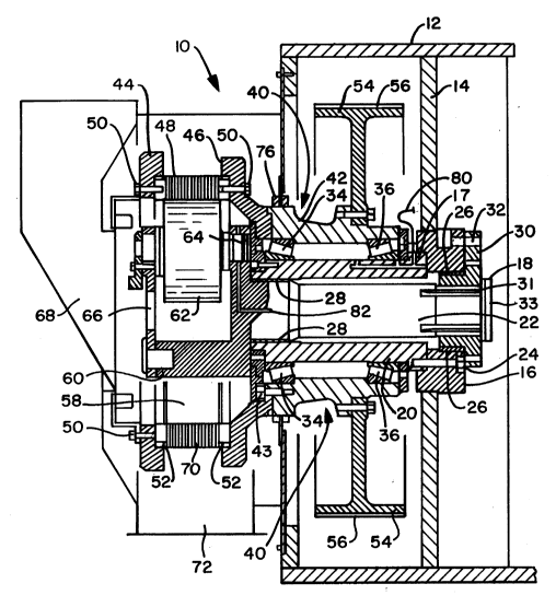
pelletizer of the invention is generally shown at 10 in
Figure 1. The pelletizer 10 has for structural support
of the other pelletizer components a main frame or
casing 12. The main frame has a main support wall 14
that is of sufficient strength to allow the components
of the pelletizer to be cantilevered from the main frame
12. Fixed to the main support wall 14 is a shaft mount
or hub 16 which defines a generally horizontal main
rotation axis. Fixed to the shaft mount 16 is a main
shaft structure 18 comprised of a tubular outer shaft 20
and a coaxial inner shaft 22. The outer shaft 20, which
can be described as a "quill shaft", is attached to
shaft mount 16 by the use of bolts 24. The outer shaft
20 fits into an annular step or shoulder 17 on the shaft
mount 16, which is welded to the main frame. The
strength of the connection of the outer shaft and shaft
mount are of significant importance to the overall
structure of the pelletizer 10. The quill shaft 20
carries a significant portion of all the weight of the
pelletizer. The quill shaft 20 transfers this weight to
the main frame 12 at the step 17 because the shaft 20 is
cantilevered from the main frame 12. The outer shaft
20, shaft mount 16 and main frame 12 function as a
unitary structure in the pref erred embodiment . The
inner shaft 22 and outer shaft 20 are held in radially
spaced apart relation to each other by use of a pair of
axially spaced bushings 26, 28.
In the preferred embodiment, the bushings 26, 28
are constructed of a PTFE-composite. The result of
ANDR1330/US
216603~
employing a PTFE-composite is a static journal bearing
that is better able to withstand the stresses of
pelletizer operation than more conventional radial
roller or tapered roller bearings. These PTFE-composite
bushings 26, 28 are capable of handling five to ten
times more static load than conventional rotating anti-
friction bearings. PTFE-composite bushings are able to
withstand 30,000 psi of dynamic high load capacity,
compared to 6,000 psi for a conventional bronze bushing.
In addition, PTFE-composite bearings can withstand
higher temperatures, up to 500F, versus 230F for a
conventional bronze bushing. Also, these PTFE-composite
bushings can absorb vibrations and shocks that would
damage metal bushings. Furthermore, PTFE-composite
bushings are not subject to galvanic, chemical and
fretting corrosion. The result is a decrease in the
occurrence of bearing seizure. Due to the self-
lubricating nature of the PTFE fibers wound in the
bushings 26, 28, complex lubrication systems are not
required to maintain the bushings in operating
condition. Quieter operation of the pelletizer results
from the use of PTFE-composite bushings because of the
lack of metal-to-metal contact that occurs in a
conventional metal bushing.
The bearings 26, 28 are not designed for continuous
rotation under the normal operating regime of the
pelletizer. The bearings only come into use to avoid
catastrophic failure of the pelletizer, i.e., allowing
rotation between the inner and outer shafts to reduce
the extent of damage to the apparatus.
Fixed to the proximal end of inner shaft 22 is
shaft cap 30. The shaft 22 is fixed to a cylindrical
portion of the shaft cap 30 by means of key ways 30 on
the inner shaft 22 into which corresponding keys on the
shaft cap 30 fit. The shaft and shaft cap then function
as a unitary component. Additionally, a lock plate 33
ANDR13301US
2166030
_ 7
fits onto the end of shaft 30 to resist lateral motion.
Shaft cap 30 has a flanged portion by which shear pins
32 fix the inner shaft in relation to the shaft mount
16. Should the inner shaft experience greater torque
than a preset amount, e.g., due to binding between the
rollers and the die, the shear pins 32 will shear
allowing the inner shaft 22 and cap 30 to rotate. The
inner shaft 22 rotates relative to the main support wall
14 and the shaft mount 16, on the PTFE-composite
bearings 26, 28. In the preferred embodiment, the
bearing 26 is disposed between the shaft cap 30 and the
shaft mount 16.
Mounted to the outer surface of the outer shaft 20
are a pair of axially spaced bearings 34, 36. In the
preferred embodiment, these are adjustable tapered
roller bearings. Tapered roller bearings are preferred
because the bearings cant inwardly toward each other to
resist lateral motion along the rotation axis of the
pelletizer. The outer shaft 20 and bearings 34, 36 are
shown in detail in Figure 2.
Surrounding the shaft mechanism 18 is a die holder
40. The die holder comprises three portions, a
substantially tubular main body 42, and two opposed
flange sections 44, 46. The main body 42 engages the
tapered roller bearings 34, 36 on the radially inside
surface of the body. The pelletizing apparatus has
means for lubricating the bearings 34, 36. These means
are generally shown at 80, 82. In the preferred
embodiment, flange 46 is fixed to the die holder main
body 42 by bolts 43, and cantilevers farther outward
than the end of outer shaft 20. Additionally, the
flanges 44, 46 of the die holder are annular and of
greater diameter than the die holder main body 42.
A die 48 is mounted on the die holder 40 by bolts
50 disposed between the flanges 44, 46. The die 48 is
further retained in proper position by annular die
ANDR13301US
2166030
-
mounts 52, which are held in press fit relation between
the die 48 and the flanges 44, 46 by the bolts 50. Also
mounted to the die holder is a flywheel 54. A belt 56
rides on the flywheel 54 to transmit power to the die
holder from a motor means (not shown). The belt 54 is
the preferred means of transmitting power to the die
holder 40 because the belt 54 does not require
lubrication, therefore reducing maintenance.
The die holder 40 and die 48 further define a
pelletizing chamber 58. Inside the pelletizing chamber
58 is a roller frame 60. The roller frame 60 is fixed
to the distal end of inner shaft 22. In the preferred
embodiment, the roller frame 60 rotatably supports a
series of rollers, one of which is shown at 62. The
rollers 62 are allowed to rotate by means of a roller
bearing 64.
In the roller frame 60 and the die holder flange 44
are material feed openings 66. These openings 66 allow
feed material to enter the pelletizing chamber 58 from
the hopper 68. During operation of the pelletizing mill
lO, feed material, such as conditioned animal feed, is
introduced from the hopper 68 into the openings 66 and
finally into the pelletizing chamber 58.
Power is applied to the mill by use of flywheel 54
to cause a rotation of the die 48. The rollers 62 are
in intimate rolling contact with the inside surface of
the die 48. As the die 48 rotates, the die causes
rollers 62 to rotate. The mill operates by feed
material being trapped between the rollers 62 and the
inside surface of the die 48. The trapped feed is then
forced through radial slots 70 to the outside surface of
the die 48. Then, knives or other means (not shown)
scrape the feed material from the outer surface of the
die 48 to form feed pellets. The resulting pellets then
fall through an opening 72 where they are collected.
ANDR/330/US
2166030
Feed material is segregated from the other portions
of the pelletizer 10 by use of a cover 74. A sealing
mechanism 76 mounted on the die holder 40 further seals
feed material from the remainder of the pelletizer. The
sealing mechanism 76 and cover serve no weight bearing
function.
During operation of the pelletizer, significant
weight transfer occurs from the rotating components to
the outer shaft 20. The weight of the die 48, die
holder 40 and flywheel 54 are transferred through the
bearings 34, 36 to the outer shaft 20. Additionally,
tension in the belt 56 on the flywheel 54 is transferred
through the bearings 34, 36 to the outer shaft 20. The
outer shaft also experiences some torque along the axis
from the belt rotating the flywheel. Proper adjustment
of the bearings 34, 36 minimizes the transferred torque.
The weight of the rollers, roller frame and inner
shaft 22 are also transferred to the outer shaft 20.
The weight is primarily transferred through the front
PTFE-composite bearings 28. 'A small portion of the
weight of the inner shaft, roller frame and rollers can
also be transferred directly to the shaft mount and
frame by the second PTFE composite bearing 26. Because
the outer shaft 20 supports most of the weight of the
pelletizer, it can be seen how important the strength of
junction is between the outer shaft 20 and the shaft
mount 16.
During pelletizer operation, inner shaft 22
experiences torque as a result of the rollers 62 being
in rolling contact with the inner face of die 48.
Additionally, feed trapped between the die and the
rollers caused resistance to rotation and further
increases the torque. Most of the axial torque applied
by the motor to the die holder by use of the belt and
flywheel are transferred to the inner shaft through the
die, rollers and roller frame. The shear pins
ANDR1330/US
2166030
- 10
sufficiently resist the axial torque produced to keep
the inner shaft`from rotating. Should the axial torque
on the inner shaft rise above a predetermined amount due
to binding of the apparatus, the shear pins will shear,
protecting the pelletizer from more significant damage.
Failure of a roller bearing 64, or material
becoming caught between the inside surface of the die 48
and the rollers 62, will result in transfer of a large
axial torque to the inner shaft 18. Normally, such a
result would damage the pelletizing apparatus. However,
in the present design, due to the split nature of the
main shaft 18, when excess torque is experienced by the
inner shaft, shear pins 32 will shear allowing the
relative rotation between the inner and outer shafts.
This rotation is of a temporary nature to allow the
pelletizing apparatus to be stopped and repaired. In
many circumstances, only the shear pins need replacement
instead of more expensive and more difficult to replace
components.
From the above description, the divided functions
of the inner and outer shafts are apparent. The outer
serves a weight bearing function and the inner shaft
serves a torque sensing function. Should binding of the
apparatus not be a concern of pelletizer operation, the
inner and outer shafts may be permanently fixed relative
to one another, not necessitating bearings 26, 28. The
inner and outer shafts can also be formed unitary as a
single shaft, still allowing employed of a reduced
number of bearings.
ANDR/330/US