Note: Descriptions are shown in the official language in which they were submitted.
WO 95/00052 PCT/US94/07229
-1-
1 Specification
2
3 "IMPROVED ANATOMICAL SUPPORT APPARATUS"
4
$ACRGROUND TO THE INVENTION
6
t
7 Bield of the Invention
8 T~~e present invention relates generally to anatomical
9 support apparatus, and more particularly to mattresses and
seat cushions having at least one thermoplastic
11 elastomeric honeycomb panel.
12
13 Description of the Prior Art
14 Substantially immobile people (i.e. wheelchair bound
users) have a great need for support cushions that
16 minimize the development of decubitus ulcers (i.e.
17 bedsores) that can occur during long periods of
18 confinements to beds or chairs.
19 Traditionally, foam and gel-filled materials have
been used in seat cushions to absorb shock, reduce
21 pressure, and provide support for wheel chair users.
22 There are many prior art seat cushions that are comprised
23 of a foam cushion encased within a washable covering,
24 wherein the foam cushion is formed so as to provide a
comfortable seating surface. For example, the foam
26 cushion may have a cut-out or contact-free zone formed
27 through it to reduce pressure on the user's spine, coccyx
28 (i.e. tailbone), or ischial tuberosities, or to eliminate
29 physical contact between the cushion and particularly
sensitive portions of the user's body.
31 In other devices, the foam is specially tapered or
32 shaped to enable the user to easily rise from the seat.
33 Shaping the foam in such cushions helps reduce high
34 pressure areas and positions the user for posturing, but
.0 35 only if the user's anatomy fits the contours of the shaped
36 foam. High pressure points will still occur if the user
37 has an anatomy that does not conform to the contours of
38 the shaped foam. This is frequently the case when the
WO 95/00052 PCT/LJS94/07129 1
_ -2-
1 user is an amputee, or is improperly positioned on the
2 cushion, or is changing positions on the cushion.
3 In yet other prior art devices, a gel or other fluid-
4 like substance fills an impermeable sack which is disposed
within or on a foam envelope. The entire assembly is
6 encased within a moisture resistant cloth, vinyl and/or
r
7 urethane, or waterproof covering and placed on a seat as
8 a seat cushion. In some cases the gel-filled cushion is
9 formed with contours or contact-free zones to relieve
contact and pressure on sensitive portions of the user's
11 body. For example, U.S. Patent 5,191,752 discloses a seat
12 cushion formed from silicon dielectric gel is used in an
13 equestrian saddle. The gel cushion, although somewhat
14 shock absorbent, is heavy and prone to damage from
punctures and the like. In U.S. Patent 5,201,780 a tri-
16 layered mattress pad is disclosed. The pad includes a
17 cover or casing containing an interior strata of a plastic
18 film layer atop a fluid bladder layer supported on a foam
19 layer. The pad is designed to reduce the development of
bedsores by reducing normal and lateral pressures and
21 forces on the bed user. As discussed below, there are
22 disadvantages associated with foam and gel-filled
23 materials.
24 One problem associated with gel materials is that
they retain heat. During periods of continuous contact
26 with a user's body, the temperature and moisture in the
27 contact areas between the gel-filled cushion and the
28 user's body also increases. An elevated gel material
29 temperature causes user discomfort and exacerbates any
existing injuries (e.g. bedsores) the user may have. The
31 moisture increase also creates an unsanitary condition for
32 the user because bacterial growth in the contact area is
33 promoted and the user's injuries are likely to become .
34 infected. '
Secondly, gel-filled cushions disposed in the
36 wheelchairs of athletic users are especially
37 uncomfortable. During outdoor athletic activity (i.e.
38 during exposure to sunlight) or during periods of physical
39 exercise, the temperature of the gel material reaches and
WO 95100052; PCT/US94/07129
-3-
1 remains at high levels. The gel material remains hot even
2 when the user stops exercising and is attempting to cool
3 down. Also, in cold weather, the gel freezes into a solid
4 or semi-solid state.
In a gel-filled cushion, the gel tends to move (i.e.
6 spread) away from the area under load. The user of the
V ,
7 cushion, or his assistant, is required to "knead" (i.e.
8 push) the gel back into the proper location beneath the
9 user's body. This is a tiring, difficult, and
l0 inconvenient activity.
11 Another shortcoming of using gel-filled cushions is
12 that the impermeable sack which contains the gel can have
13 a hammocking effect on the user's prominences. This
14 causes high pressure zones beneath the protruding areas
resulting in sores or other injury.
16 Finally, gel-filled cushions are relatively heavy,
17 and especially vulnerable to damage or destruction from
18 puncturing.
19 In addition, there are shortcomings associated with
foam materials which, for example, are susceptible to
21 taking a compression set after many periods of use. It is
22 tyL~ical, that after a prolonged period of use the foam
23 cells collapse and the support benefit of the cushion is
24 lost. Also, foams cushions must be encased within
impermeable coverings because they readily absorb fluids.
26 The foam cushion must be replaced if incontinence or an
27 accidental spill wets a cushion with a torn covering.
28 Some wheelchair cushions utilize pneumatic devices as
29 a pressure relieving system for reducing ischemic injury.
U.S. Patent 5,193,237, for example, discloses a pneumatic
31 wheelchair cushion having a number of separate unattached
32 air sacks arranged in a matrix. Reduced airflow and
33 therefore reduced air pressure is periodically provided
34 within the cushion so that each air sack will have reduced
pressure for a predetermined period of time. A self-
36 regulating air distribution is provided such that when the
37 occupant shifts his/her weight so as to overcome the air
38 pressure in a sack, the system automatically backflows air
39 into that particular sack thereby cushioning the user.
WO 95/00052 PCT/US94/07I29
- -4 -
1 The disclosed wheelchair device is complex, and
2 requires electrical power and pressurized air. Such
3 devices are overly complicated, costly to acquire, and
4 costly to maintain. Also, the air cushion device must be
frequently adjusted, can be punctured, and is unstable for
6 a user.
Y
7 In addition, there are some prior art mattresses that
8 include a matrix of air cells that are inflated and
9 deflated to more evenly support bodies and reduce the
development of bedsores. In addition to the air supply
11 components (e. g. compressor, valuing, tubing, etc.) these
12 mattresses also require a computer to constantly measure
13 the resistance in each air cell and to control the
14 reaction of each cell to pressure and load changes by
varying the deflation and inflation in each cell. These
16 devices are also costly, complicated, require adjustment,
17 and subject to puncture damage.
18 The prior art also discloses resilient honeycomb
19 structures used in personal-use items. U.S. Patents
5,134,790 and 4,485,568 disclose using resilient honeycomb
21 structures in the sole of shoes. Also, U.S. Patent
22 4,422,183 to Landi et al. discloses a protective body
23 shield having a honeycomb structure constructed from a
24 resilient flexible material. Finally, U.S. Patent
5,203,607 discloses an improved bicycle seat including a
26 rigid shell supporting a foam layer having a pad of
27 thermoplastic elastomer honeycomb disposed within or
28 thereon. In all of these devices, the honeycomb
29 structures are not utilized in seat cushions and
mattresses.
31 Thus, there is a need to provide an improved
32 anatomical support apparatus that maximizes pressure
33 relief, stability, comfort, durability, maintainability,
34 and weight, yet does not possess the short-comings of the
presently employed devices.
36
WO 95/00052 PCT/US94/07I29
-5-
1 SUMMARY OF THE INVENTION
2 Obieats of this Invention
3 It is therefore an object of the present invention to
4 provide an improved anatomical support apparatus that
provides improved pressure relief and stability
6 characteristics, significant compression set resistance,
7 durability, low weight, and low maintenance properties.
8 It is another object of the present invention to
9 provide an improved anatomical support apparatus having
at
least one thermoplastic elastomer honeycomb panel that
11 conforms, supports, and stabilizes a wide variety of
12 sitting positions, user anatomies and disabilities.
13 It is still another object of the present invention
14 to provide an improved anatomical support apparatus that
is breathable to permit cooling of the user.
16 Another object of the present invention is to provide
17 an improved anatomical support apparatus that can be
18 tailored to create the desired cushioning and stabilizing
19 characteristics without having to introduce elements such
as foam, fluids or other elements which add cost or reduce
21 durability.
22 Still another object of the present invention is to
23 provide an improved anatomical support apparatus
24 constructed of materials that are fast drying, and can be
easily disinfected and sterilized by chemical wash,
26 microwave, detergent, or other means.
27 Another object of the present invention is to provide
28 an improved anatomical support that has at least one
29 flexible thermoplastic elastomeric honeycomb having at
least one contoured surface engagable with a body area of
31 a user.
32 Briefly, an improved anatomical support apparatus
33 includes a frame for supporting the apparatus, an outer
34 envelope and a resilient inner body encased within the
envelope, both the inner body and the outer envelope
36 resting on the frame. The inner body including a first
3 7 panel having at least one honeycomb core , f first and second
38 facing sheets. The core is formed of undulated strips of
39 resilient thermoplastic material, thermal compression
WO 95/00052 - ~ PCT/IJS94/07129
-6-
1 bonded together to form cell walls defining a plurality of
2 contiguous regularly shaped cells. The first facing sheet
3 is formed of resilient thermoplastic material that is
4 thermal compression bonded to an upper face of the core
formed by upper extremities of the cell walls. The
6 bonding is accomplished by simultaneously applying heat
7 and pressure to the joinder of the first facing sheet and
8 the core. The second facing sheet is similarly formed
9 from resilient thermoplastic material and is thermal
compression bonded to a lower face of the core formed by
11 lower extremities of the cell walls, the bonding being
12 accomplished by simultaneously applying heat and pressure
13 to the joinder of the second facing sheet and the core.
14 The core anisotropically flexes to stabilize and spread
the load exerted by the user.
16 In an alternate embodiment of the present invention,
17 an improved anatomical support apparatus includes at least
18 one contoured substrate and at least one planar substrate
19 attached to the contoured substrate. The contoured
substrate includes a first honeycomb core formed of
21 undulated strips of resilient thermoplastic material,
22 thermal compression bonded together to form cell walls
23 defining a plurality of contiguous regularly shaped cells.
24 Each of the cell walls having an upper extremity and a
lower extremity, and at least one of the upper and the
26 lower extremity forming a contoured surface. The
27 contoured substrate further includes means for maintaining
28 the first core in its expanded configuration. The planar
29 substrate is attached to one of the upper and the lower
extremity of the first core, and includes a second
31 honeycomb core formed of undulated strips of resilient
32 thermoplastic material, thermal compression bonded
33 together to form cell walls defining a plurality of ,
34 contiguous regularly shaped cells. Each of the cell walls
having an upper extremity and a lower extremity, each of ,
36 the upper and the lower extremity forming a planar
37 surface. In addition, the planar substrate also includes
38 means for maintaining the second core in its expanded
39 configuration. The first and the second cores being
WO 95/00052 PCT/US94/07I29
1 anisotropically flexible and capable of stabilizing and
2 spreading a load exerted thereupon by said user of the
3 cushion.
4 An important advantage of the present invention in
that the thermoplastic elastomer honeycomb panel used in
6 the construction of the apparatus is an anisotropic
7 material having improved pressure relief, stability,
8 compression set resistance, durability and low maintenance
9 characteristics.
Another advantage of the present invention is that
11 single or multiple thermoplastic elastomer honeycomb
12 panels may be configured within the anatomical support
13 apparatus to customize and individually tailor it for an
14 individual user.
Yet another advantage of the present invention is
16 that an anatomical support apparatus can support and
17 conform to a wide range of user support positions, user
18 anatomies and disabilities.
19 Yet still another advantage of the present invention
is that entire or only portions of the anatomical support
21 apparatus may be pressurized to create different support
22 and stability characteristics.
23 Yet another advantage of the present invention is
24 that the anatomical support apparatus may be constructed
from a perforated core thermoplastic elastomer honeycomb
26 panel and perforated faces that is breathable to allow
27 perspiration removal and cooling of the apparatus user.
28 Another advantage of the present invention is that
29 different thermoplastic elastomer honeycomb core designs
or multiple panels of different thermoplastic honeycomb
31 core designs may be utilized to maximize design
32 flexibility of the improved anatomical support apparatus.
33 Still another advantage of th=..= present invention is
34 that the thermoplastic elastome~- honeycomb core is
fabricated from recyclable materials that are fast drying,
36 and easily disinfected and sterilized.
37 These and other objects and advantages of the present
38 invention will no doubt become apparent to those skilled
39 in the art after having read the following detailed
WO 95/00052 PCT/US94/07129
_g_
1 description of the preferred embodiment which is contained
2 in and illustrated by the various drawing figures.
3
4 BRIEF DESCRIPTION OF THE DRAWINGS
In the accompanying drawings:
6 Fig. 1 is a perspective view illustrating a
7 wheelchair having disposed thereon an improved anatomical
8 support cushion constructed in accordance with a preferred
9 embodiment of the present invention;
Fig. 2 is a perspective view illustrating a
11 thermoplastic honeycomb panel of the type utilized in the
12 improved anatomical support cushion shown in Fig. 1,
13 wherein the panel has a non-perforated honeycomb core;
14 Fig. 3 is a partial cross-section taken through the
line 3-3 of the panel illustrated in Fig. 1 to illustrate
16 the structural characteristics of one embodiment of the
17 panel;
18 Fig. 4 is a partial cross-section illustrating an
19 alternative embodiment of the panel illustrated in Fig. 2;
Fig. 5 is a perspective view of another thermoplastic
21 honeycomb panel of the type utilized in the improved
22 anatomical support cushion shown in Fig. s, wherein the
23 panel is shown with a non-perforated facing sheet broken
24 away to reveal a perforated honeycomb core, and also
illustrated is a separate section of the panel having a
26 perforated honeycomb core as well as a perforated facing
27 material;
28 Fig. 6 is a partially broken depiction of a
29 thermoplastic honeycomb panel, similar to the panel
illustrated in Fig. 5, communicatively coupled to a bulb
31 pump;
32 Fig. 7 depicts a force deflection comparison plot
33 between a seat cushion utilizing foam or gel materials and
34 an improved cushion having a thermoplastic honeycomb panel
of the present invention;
36 Fig. 8 illustrates the idealized honeycomb seating
37 cushion design parameters;
WO 95100052
PCT/US94/07129
_9_
1 Fig. 9 illustrates the buttressing effect of the
2 cells of a thermoplastic flexible honeycomb panel of the
3 present invention when loaded by a wheelchair user;
4 Fig. 1oA through 10E are cross-sectional views of the
cushion illustrated in Fig. 1 wherein alternative
6 thermoplastic flexible honeycomb panel configurations are
7 illustrated;
8 Fig. 11 is a perspective view of a flexible
9 thermoplastic honeycomb panel of the type illustrated in
Fig. 1, partially broken to show a flexible honeycomb core
11 insert disposed on a conventional foam cushion;
12 Fig. 12 is a cross-sectional view of the panel
13 illustrated in Fig. 11;
14 Fig. 13 is a perspective view of an improved
anatomical support cushion having a foam layer and a
16 plurality of independent flexible thermoplastic honeycomb
17 pad sections that are fitted into cavities pre-formed
18 within the foam layer;
19 Fig. 14 is a perspective view of an improved
anatomical support apparatus of the present invention used
21 in a bed disposed on a standard hospital bed frame;
22 Fig. 15 is an enlarged perspective view of the bed
23 including a mattress pad of the present invention; and
24 Fig. 16 is a cross-sectional view of the bed taken
along the line 16-16 of Fig. 15;
26 Fig. 17 is a perspective view of an alternate
27 embodiment of the present invention including a cushion
28 having at lease one contoured substrate made from a
29 thermoplastic elastomeric honeycomb panel;
Fig. 1$ is a partial sectional view of one embodiment
31 of the cushion shown in Fig. 17, having a contoured upper
32 substrate;
33 Fig. 19 is a partial sectional view of another
34 embodiment of the cushion shown in Fig. 17, having a
contoured intermediate substrate;
36 Fig. 20 is a partial sectional view of yet another
37 embodiment of the cushion shown in Fig. 17, having a
38 contoured upper substrate and a stiffened intermediate
39 substrate; and
WO 95/00052 PCT/LTS94/07129
-10-
1 Fig. 21 is a partial sectional view of still another
2 embodiment of the cushion shown in Fig. 17, having a
3 contoured upper substrate and a facing sheet disposed
4 therein.
6 DETAILED DESCRIPTION OF THE EMBODIMENT
7 Referring now to Fig. 1 which depicts a conventional
8 wheelchair 10 having disposed thereon a removable improved
9 anatomical support cushion 12. As will be described in
greater detail below, the cushion 12 is constructed of at
11 least one flexible thermoplastic elastomer honeycomb core
12 panel built in accordance with the present invention. It
13 should be noted that, although the cushion 12 is
14 particularly well suited for wheelchair applications, the
cushion 12 may be used in a variety of other anatomical
16 support applications (e.g., mattresses, automobile and
17 airline seats, arm rests, seat belts, etc.).
18 Referring to Fig. 2 which illustrates a honeycombed
19 panel structure 14 constructed from thermoplastic
- 20 elastomer materials. The panel 14 includes a honeycomb
21 like core preferably made of bonded together and expanded
22 strips or ribbons 16 of plastic material to which facing
23 sheets 18 and 20 of perhaps heavier gauge material are
24 thermocompression bonded. The panel is an anisotropic
three-dimensional structure having predetermined degrees
26 of flex along the X, Y and Z axis. Each cell is formed,
27 in part, by four generally S-shaped wall segments each of
28 which is shared by an adjacent cell. In addition, each
29 cell shares a double thickness wall segment with two
adjacent cells.
31 Panel 14 has high tear and tensile strength and is
32 highly resilient, with optimal compression load and shock
33 absorption or distortion characteristics yet is extremely ,
34 light weight. Selected combinations of elastomer
material, honeycomb cell configurations, core thickness
36 and facing material variables will determine the panel's
37 characteristics of softness or hardness, resilient
38 recovery rate and rigidity or flex as required for a
39 particular application. The facing materials can be
CA 02166106 1998-12-21
WO 95/00052 _ -:, :y PCT/US94/07I29
-11-
1 selected from a wide variety of films, including
2 thermoplastic urethanes, foams, EVAs, rubber, neoprene,
3 elastomer impregnated fibers and various fabrics, etc.
4 The manufacturing and fabrication of the panel 14 is
described in greater detail in our U.B. Patent 5,039,567
6
7 Fig. 3 is a cross-sectional view taken along the line
8 3-3 of Fig. 2. As illustrated, each wall of the core will
9 have a structure which resembles an I-beam, as indicated
at 22, and upper and lower faces 24 and 26, either or both
11 of which may be deformed during a planarization operation
12 as disclosed in our above identified U.S. Patent to
13 stabilize the honeycomb core and prevent the expanded
14 strip from collapsing. The faces 24, 26 are firmly bonded
to the facing sheets 18 and 20. In addition, as
16 illustrated in Fig. 2, each cell will be formed of four
17 generally S-shaped vertical wall segments 28 joined
18 together with two wall segments 30 and 32 of double
19 thickness. With the top and bottom edges of these walls
bonded to the upper and lower facing sheets 18 and 20 a
21 unitary honeycomb panel is provided with no seams or
22 separations. Because of the high integrity of the bonds
23 between the core and facing sheets, the anisotropic
24 features of the structure will be uniform and predictable.
In addition, as illustrated in Fig. 4, a multi-cored
26 structure may be built up as depicted at 34. Such
27 structure car_ include different core configurations 36 and
28 38 as well as different types of facing materials 40, 41,
29 and 42. It will, of course, be appreciated that within a
30~ single core cell, dimensions may be varied by changing the
31 dimensions and/or spacings of the bonding ribs used during
32 the build-up of the core stack.
33 Fig. 5 is a perspective view of a perforated core (or
34 perforated cell wall) honeycomb panel 44. The panel 44 is
broken into two sections, a left hand section 45 and a
36 right hand section 46 in order to more fully illustrate
37 alternative embodiments. The left half 45 shows material
38 having a perforated honeycomb core 48 and unperforated or
39 solid facing sheets 49 and 50. The dashed lines 51
CA 02166106 1998-12-21
WO 95/00052 ~._ ,Y;~ ' PCTlUS94107129
-12-
1 illustrate the normal full coverage of the top facing
2 sheet 49.
3 The honeycomb core 48 is made from sheets of a
4 selected grade thermoplastic elastomeric material that has
been perforated such that a matrix of small holes 59
6 exists throughout. The sheets are compression bonded
7 together in spaced intervals staggered between alternating
8 sheets as described in our U.S. Patent 5,039,567. The resulting stack is
9 then cut into strips which, when expanded, create a
'' honeycomb network of elongated, generally hexagonally
11 I shaped cells 52.
12 Each cell 52 of the honeycomb-core 48 is defined by
13 four generally S-shaped wall segments, each interior wall
14 of which is shared by an adjacent cell. The wall segments
of each cell 52 include a single thickness wall portion 54
16 and a double thickness wall portion 56.
17 The upper and lower faces 58 and 60 of the walls
18 forming several cells are deformed during a planarization
I9 operation as disclosed in our above-identified U. S . Patent
to stabilize the honeycomb core and prevent the expanded
21 strip stock from collapsing. Facing sheets 49 and 50, cut
22 from sheets of resilient thermoplastic material, are then
23 compression banded to the upper and lower faces 58 and 60.
24 The addition of the facing sheets 49 and 50 strengthens
the core 48 and provides an ample surface for adhering
26 another panel or other material.
27 The right half section 46 of the panel depicted in
28 Fig. 5 includes a perforated honeycomb core 47 similar to
29 the left hand section 45 of the panel, but has facing
30~ sheets 55 and 53 made of perforated material. Dashed
31 lines 57 indicate the honeycomb pattern of the core 47
32 underneath the top facing sheet 55. By perforating both
33 the honeycomb core and facings, the weight of the material
34 is reduced while the resiliency and flexibility is
increased. The weight is reduced because the perforations
36 reduce the overall quantity of the material comprising the
37 honeycomb and facings. Similarly, the flexibility is
38 increased because there is less material to constrain each
39
CA 02166106 1998-12-21
WO 95/00052 : PCT/TJS94/07129
-13-
1 segment of the material from bending. The resiliency, or
2 ability of the structure to spring back to its original
3 form after being compressed, is also enhanced by virtue of
4 the additional passages through which air can return to
fill the cells. It will be appreciated that the resilient
6 but damped restorative characteristics of the~structure
7 make it an excellent absorber of shock waves.
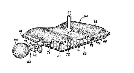
8 Referring now to Fig. 6 which depicts a pressurized
9 honeycomb panel 62 including a pump subsystem 63, and a
perforated core honeycomb panel subsystem 64.
11 The subsystem 64 includes a first facing sheet 66, a
12 second facing sheet 68, and a flexible perforated
13 honeycomb core 70. The core 70 is described in greater
14 detail in our U.S. Patent 5,180,619. The core 70 includes cell
walls 71 with perforations 72 and is affixed to the inside
16 surfaces of the first facing sheet 66 and the second
17 facing sheet 68. The facing sheets extend outwardly
18 beyond the core 70 and are bonded together around their
19 perimeters as indicated at 74 so as to form an enclosed
chamber 76 which is hermetically sealed and adapted to
21 contain a suitable gas. For purposes of illustration, the
22 chamber walls are broken away as indicated at 78.
23 In order to permit the gas contained within the
24 enclosed chamber 76 to be increased or decreased in volume
or pressure, the pump subsystem 63 is communicatively
26 coupled to the chamber 76. The subsystem 63 includes a
27 bulb pump 80 that is coupled via a conduit 81 to the
28 chamber 76. An exhaust valve 82 is installed in the
29 conduit 81 and allows the chamber 76 to be vented to
atmosphere. As will be appreciated by those skilled in
31 the art, the selected addition or subtraction of gas into
32 or out from the enclosed chamber 76 will result in a
33 change in the force-dissipating characteristics or shock
34 absorbing capabilities of the panel in response to applied
forces such as illustrated by the arrow 83.
36 Honeycomb, and particularly anisotropic honeycomb has
37 a number of beneficial characteristics for anatomical
38 support applications in general, and particularly for
39
WO 95/00052 PCT/US94/07129
-14-
1 mattress and seating applications where the disadvantages
2 of more traditional materials, such as gels and foams,
3 become particularly unacceptable. Important
4 characteristics for general seating, and especially for .
wheelchair seating materials, include pressure relief
6 (load spreading), comfort, stability, durability, low
7 maintenance, light weight, and low transmissibility (good
8 impact isolation).
9 Pressure relief is particularly important for
wheelchair seating applications because local pressure
11 spots, within the range of 60-80 mm Hg (1.16 - 1.55 psi),
12 quickly develop into sores on relatively immobile people.
13 Seat cushions having honeycomb panels of the present
14 invention are ideal for use as wheelchair cushions because
such panels have relatively flat force deflection
16 characteristics. Fig. 7 shows a force-deflection plot 84
17 of a foam cushion compared to a force deflection plot 86
18 of a cushion having a honeycomb panel of the present
19 invention. The modulus (i.e. compressive force divided by
deflection) over a 15 to 55 percent deflection range, for
21 foam is depicted by a line 88. The modulus, over the same
22 deflection range, for honeycomb of the present invention
23 is depicted by a line 89. The figure shows that the
24 modulus for the honeycomb panel cushion is approximately
one-fourth that of the foam cushion. Pressure variations,
26 in the honeycomb panel cushion caused by anatomical
27 features (i.e protrusions) of the wheelchair user, are
28 approximately one-fourth those of foam cushions. Thus, a
29 wheelchair user's anatomical protrusions are less likely
to cause local high pressure spots and bed sores if the
31 user sits on a honeycomb panel cushion of the present
32 invention rather than on a typical foam cushion.
33 The characteristic of honeycomb that makes it an
34 ideal in this area is the relatively flat "plateau region'°
that characterizes the honeycomb panel's force-deflection
36 property. In Fig. 8, a force-deflection relationship or
37 line 90 is plotted for honeycomb constructed in accordance
38 with the present invention. The force-deflection line 90
39 is measured over a useable deflection range 91 that ranges
WO 95/00052. p PCT/US94/07129
-15-
1 from 0 to nearly 80 percent deflection. It will be noted
2 from the figure that there are three distinct regions in
3 the force-deflection line. There are two regions where
4 the modulus (i.e. slope) of force over deflection is very
steep, that is, the modulus one region 92 and the
6 boi~toming region 94. However, in the plateau modulus
7 region 93, which extends over the plateau region
8 deflection range 95 (i.e. roughly 8-75 percent
9 deflection), the slope of the line is relatively flat. If
the honeycomb configuration is properly selected such that
11 the weight of the wheelchair user divided by his sitting
12 area places the user in the middle of the plateau modulus
13 region 93 then local increases or decreases in cushion
14 def lection caused by the user s anatomical features do not
appreciably change the pressure exerted on the user. In
16 other words, the user s anatomical protrusions do not
17 create the local high pressure spots which could lead to
18 bedsores and other similar ulcerations. In engineering
19 terminology, the compressive modulus of honeycomb
constructed in accordance with the present invention, is
21 less over the plateau region 93 than the compressive
22 modulus of typical foam or gel seat cushions.
23 Pressure relief by itself is not sufficient to make
24 a satisfactory wheelchair seating cushion because
stability must also exist. The best pressure relief
26 system is ineffective if during maneuvers or motions the
27 user tips or slides off the seating area of the cushion.
28 Fig. 9 depicts the self-aligning and supporting
29 characteristic of honeycomb panels of the present
invention. A user profile 96 is illustrated as being
31 disposed onto a seat cushion 97 constructed from a
32 honeycomb panel of the present invention. As depicted at
33 98, in response to the user load, the honeycomb cells tend
34 to align themselves in a buttressing manner with the
applied load, even as the load shifts. This effect can be
36 enhanced by selecting a softer honeycomb for the topmost
37 layer of the cushion, in effect creating a buttressed
38 pocket for the lateral portions of the thighs and
39 buttocks. In addition, the anisotropic flexing
WO 95/00052 ~ .PCT/1JS94/07129
-16-
1 characteristics of a single and double walled honeycomb
2 provide enhanced stability (i.e. greater shear modulus) in
3 the direction of the double walls. Depending on the needs
4 and activity level of the user, this orientation can be
changed to provide the most effective support. For a
6 typical user (this would be support in the fore and aft
7 orientation to help prevent slumping or sliding off the
8 cushion.
9 Another principal benefit of the honeycomb cushion
characterized by the present invention is the ability to
11 tailor it (e. g. varying materials, varying cell
12 configuration and size, etc.) to create the desired
13 cushioning and stabilizing characteristics. The honeycomb
14 panel may be tailored either by adding other components,
e.g. fluids, or by not introducing elements such as
16 fluids, foam, or other elements which add costs and reduce
17 durability. As an example, one or more layers of the
18 honeycomb cushion can contain perforated cells walls,
19 which in effect creates a configuration that breathes like
an open cell foam but without the foam's porosity and
21 resultant susceptibility to absorbing liquids. A
22 perforated cell honeycomb can provide performance benefits
23 such as quicker recovery from loading and a lower modulus
24 with greater displacement capability than the same
configuration in enclosed cell honeycomb. In conjunction
26 with the inflation device and valve arrangement, as
27 illustrated in Fag. 6, the perforated cell cushion with
28 sealed edges can be pressurized to increase the air
29 cushion effect in situations where this is beneficial.
Note that a perforated honeycomb air cushion is much more
31 shear resistant, thus more stable, than an equivalent
32 conventional air cushion.
33 Compression set resistance and resistance to repeated
34 loadings, i.e. good material memory, are also important
benefits of a seat cushion having honeycomb of the present
36 invention. The compressive resistance and recovery of
37 both honeycombs and foams comes from bending of the °'strut
38 elements" which comprise their geometries. These strut
39 elements are more uniform in honeycomb than foam. Because
WO 95/0005a
PCT/US94/07129
-17-
1 of this greater uniformity, the compression set resistance
2 and recovery is greater in honeycomb than in foam. In
3 addition, closed cell (faced) honeycomb has the additional
4 resilience afforded by the integral trapped air creating
an air spring. Comparison testing of honeycomb and foam
6 configurations used for seating applications in which
7 comparable samples were loaded daily for 16 hours on and
8 8 .hours off, revealed 1.5 to 2.0 percent compression set
9 for the foams compared to less than 1 percent for
honeycombed seating cushions of the present invention.
11 Also, the honeycomb seating cushions of the present
12 invention are light weight and require low maintenance.
13 Weight is an important factor during transfer operations
14 of the wheelchair into and out of a vehicle. Low
maintenance and ease of cleaning are important because a
16 wheelchair cushion cannot necessarily be quickly replaced
17 if incontinence or an accidental spill wets the cushion.
18 Honeycomb panels of the present invention typically have
19 solid facing sheets which act as washable barriers that
will not absorb water like foam cushions. Nor are
21 honeycomb panels susceptible to puncturing like some of
22 the gel- filled cushions currently available.
23 Referring now to Fig. l0A through 10E wherein are
24 depicted cross sectional views of an improved cushion in
accordance with the present invention. Fig. l0A depicts
26 ~ a single flexible honeycomb panel 100 encased within a
27 vinyl or similar covering 102. The panel 100 is
28 constructed in accordance with the referenced U. S. patents
29 and includes a non-perforated core 104, and facing sheets
103 and 105. Although a single unperforated cell wall
31 honeycomb panel is illustrated it will be appreciated that
32 in the alternative a single perforated core honeycomb
33 panel may be used as an alternative embodiment.
34 In an alternate embodiment not shown, the panel 100
could be removed from the covering 102 and either or both
36 of the facing sheets 103 and 105 perforated in a
37 predetermined pattern. The area of the perforations could
38 be varied depending on the specific requirements of the
39 user. For example, if a particular user needed greater
WO 95/00052 PCT/US94/07129
-18-
1 cushioning for a certain region of his body, the facing
2 sheets for the cushion area supporting this body region
3 could be perforated. In this manner, the cushion
4 apparatus can be individually customized to a user's
specific needs. Perforating the cushion in a
6 predetermined manner to accommodate specific user
7 requirements can be utilized for any embodiment of the
8 present invention.
9 Referring to Fig. lOB which illustrates two
perforated core honeycomb panels 104 and 106 encased
11 within the covering 102, it should be noted that honeycomb
12 panel 104 is of different size cell construction than
13 honeycomb panel 106, panel 106 having larger cell walls as
14 illustrated in the figure. Further, although an
embodiment with two different honeycomb panels has been
16 illustrated it is possible to construct the cushion with
17 two equally sized honeycomb panels. Alternately,
18 different types of honeycomb panels may be mixed according
19 to the supporting properties desired. For example, panels
having different core designs (i.e., cell size,
21 configuration, or materials) may be used. Also, a non-
22 perforated cell wall honeycomb panel may be configured
23 with a perforated cell wall honeycomb panel and vice
24 versa. In addition, two or more layers of honeycomb
panels may be stacked in accordance with the descriptions
26 referenced earlier in our prior U.S. patents.
27 Referring to Fig. lOC which depicts an improved
28 cushion having a pressurized honeycomb panel 110 encased
29 within the covering 102. As described earlier, the
pressurized honeycomb panel 110 is comprised of a
31 perforated honeycomb core 112, encased within a non-
32 perforated facing sheet covering 114, that is in
33 communication with a pump subsystem 116, via a conduit .
34 118. In this manner, the pressurized honeycomb panel 110
may be alternatingly pressurized to vary the support
36 characteristics of the honeycomb core 112 contained
37 within.
38 Referring to Fig. lOD which illustrates a multi-layer
39 cushion having a plurality of honeycomb panels contained
WO 95/00052, PCT/US94/07129
-19-
1 within a covering 102. In this particular embodiment, the
2 pressurized honeycomb panel 110 is attached to a non-
3 perforated core honeycomb panel 120. Alternately, two
4 pressurized honeycomb panels could be used with each panel
system having different properties, i.e. different
6 materials and/or cell configurations and sizes. In
7 addition, each individual panel could have different
8 stiffnesses in different areas. For example, a stiffer
9 area would be placed in a forward area where the user's
l0 leas and thighs are supported, and a softer area placed
11 beneath the buttocks area. This can be accomplished by
12 constructing the panels with more than one cell
13 configuration. In another embodiment not depicted in the
14 figure, the panel 120 could have perforated cells walls
rather than non-perforated cell walls as illustrated.
16 Finally, although two honeycomb panels are depicted, more
17 than two panels could be employed, and the arrangement of
18 panels could have a pressurized panel disposed between
19 non-pressurized panels or a non-pressurized panel disposed
between two pressurized panels.
21 Fig. l0E illustrates a multi-layer apparatus 164
22 having a two-layer panel subsystem 166 disposed onto a
23 pump subsystem 168. The panel subsystem 166 includes
24 pressurized honeycomb panels 170 and 172. Each panel has
perforated cell walls 176, 178 and facing sheets 170a and
26 170b, 172a and 172b. Each facing sheet has a plurality of
27 perforations 176a and 176b, and 178a and 178b. The two
28 panels 170 and 172 are covered by a permeable covering 174
29 that permits the passage of fluid (e.g. air) from the
panels 170 and 172. The pump subsystem 168 includes a
31 base plate 180 having a channel 182 formed therein so that
32 the channel can be communicatively coupled, via a conduit
33 168, to a pump or fan device 188. A plurality of exhaust
34 ports 184 are formed in a surface 181 of the base plate
180 and intersect with the channel 182. The pump device
36 188 is also communicatively coupled to a fluid source (not
37 shown) via an input conduit 189.
38 Fluid (e.g. air) is drawn from the fluid source, in
39 the direction indicated by the arrow 190, by the pump
WO 95/00052 PCT/LJS94/07129
-20-
1 device 188. Fluid is passed through the conduit 186 into
2 the channel 182 and out through the ports 184 of the base
3 plate 180. The fluid passes through the contacting
4 permeable covering 174 and into the panel 172, via the
perforations 178b in the facing sheet 172b. The fluid
6 passes from the panel 172 to the panel 170 via the
7 perforations 178, 178a, and 176b. Finally, the fluid
8 exits the panel 170, via the perforations 176 and 176a,
9 out through the permeable covering 174. The fluid exiting
from the apparatus cools and comforts a user sitting
11 thereon.
12 It will be appreciated that only one panel or even
13 additional panels may be utilized to maximize the comfort
14 and support for a particular user. Also, a perforated
covering may be used in lieu of the permeable covering
16 174. Further, the pump device 188 may draw from a variety
17 of fluid sources other than the ambient environment.
18 Although not illustrated, an alternate pump subsystem
19 may include a pump device communicatively coupled to a
porous conduit. The conduit being similarly disposed as
21 the base plate 180 or, in the alternative, the conduit
22 could be disposed underneath the uppermost panel (e. g.
23 between panels 170 and 172) for supplying cooling air
24 through panel 172 to the user.
Fig. 11 illustrates a partially broken view of yet
26 another alternative embodiment of an improved cushion 122.
27 The cushion 122 includes a honeycomb core 126, facing
28 sheets 128 and 129, a foam pad 130, all encased within a
29 covering 124. As more clearly illustrated in Fig. 12, the
honeycomb core 126 is disposed on top of the foam 130.
31 Although a non-perforated honeycomb core is illustrated,
32 a perforated cell wall honeycomb core could be utilized,
33 or alternatively a pressurized honeycomb panel system
34 could be utilized. Fig. 13 illustrates still another
embodiment of the seat cushion 122 wherein a plurality of .
36 cavities 132 and 134 are disposed on the surface of the
37 seat cushion 122. Within each cavity a separate honeycomb
38 core insert 136 is placed. The particular inserts
39 illustrated in Fig. 13 are non-perforated cell wall
WO 95100052 _, ,, PCT/I1S94/07129
-21-
1 honeycomb core inserts with top and bottom facing sheets
2 138, 140. In the alternative, the core inserts 136 could
3 be constructed from perforated cell wall honeycomb panels
. 4 or pressurized honeycomb panels. Although only two core
inserts have been illustrated in the figure, a plurality
6 of core inserts could be installed on numerous locations
7 on the surface of the cushion to vary the support
8 characteristics of the cushion to conform to the
9 individual needs of the wheelchair user. Thus, core
inserts of varying stability and stiffness could be
11 interchanged to individually tailor the support and
12 pressure relief characteristics of the cushion. Although
13 not illustrated, in a multi-layer cushion apparatus, the
14 core inserts could be removable from any of the panels
(i.e. in a three layer apparatus, the core insert could be
16 removable from the second panel).
17 A logical extension of the anatomical support cushion
. 18 described above is a pad used for supporting the buttocks,
19 shoulders, head, and other parts of the anatomy of a
reclining or sitting user. Fig. 14 is a perspective view
21 of a bed 142 supported on a standard hospital bed frame
22 144, the bed 142 having carrying straps 146 disposed at
23 numerous location around its periphery. The bed 142 of
24 the present invention is not limited to use in a hospital
environment but may be used in other human care facilities
26 (e.g. nursing, convalescent, retirement homes, etc.) or
27 other environments.
28 Fig. 15 depicts an enlarged perspective view of the
29 bed 142 illustrated in Fig. 14, but with the carrying
straps 146 omitted for clarity. The bed 142 includes a
31 mattress 150 with a mattress pad 148 dispose thereon and
32 which covers the entire mattress 150. It will be
. 33 appreciated, however, that the mattress pad 148 could be
34 sized such that it covers only a portion or discrete
portions of the mattress 150. As illustrated in the
36 cutaway portion, the mattress pad 148 includes a honeycomb
37 core panel 152 having a facing sheet 154 and a facing
38 sheet 160 (not shown). The honeycomb core panel 152 can
39 be configured in ways different than the type illustrated,
WO 95/00052 PCT/US94/07129
- -22-
1 i.e. perforated cell walls, unfaced honeycomb core, etc.
2 Fig. 16 is a cross-sectional view taken along the
3 line 16-16 of Fig. 15, and depicts the construction of the
4 mattress pad 148 and mattress 150. The mattress 150
includes a foam core 152 encased within a mattress
6 covering 154. The mattress pad 148 includes the honeycomb
7 core panel 152, facing sheets 154 and 160, and a pad
8 covering 162 encasing the panel 152 and facing sheets 154
9 and 160.
Fig. 17 is a perspective view of a contoured seat
11 cushion 200 which is an alternate embodiment of the seat
12 cushion 12 depicted in Fig. 1. Seat cushions, fabricated
13 from at least one panel of flexible thermoplastic
14 elastomeric honeycomb and having a planar or non-contoured
surface engagable with a body surface (e. g., thighs,
16 buttocks) of a user, provide pressure relief, stability,
17 durability and washability. However, a planar engagable
18 surface does not provide as much positioning and posture
19 control of the user as does a non-planar or contoured
engagable surface.
21 The contoured seat cushion 200 includes an upper
22 layer 206, an intermediate layer 208, and a bottom layer
23 210. Each layer is fabricated from thermoplastic
24 elastomeric honeycomb in the manner described above, and
the construction of each of the cells of the honeycomb
26 panels of the layers is also as described above. Each
27 cell wall of each layer has an upper extremity and a lower
28 extremity (best seen in Fig. 18-21). The intermediate
29 layer 208 is sandwiched between the layers 206 and 210 and
is attached to the lower extremity 252 and the upper
31 extremity 258 of the upper layer 206 and the bottom layer
32 210, respectively.
33 In addition, a surface 205 formed by the upper
34 extremities 250 of the cell walls of the upper layer 206
has been sculpted or shaped to provide the distinctive -
36 illustrated contoured features depicted in Fig. 17. The
37 directional terminology adapted for the cushion 200 is
38 also illustrated in Fig. 17. A direction 201 is
WO 95/00052 " PCT/US94/07129
-23-
1 designated as "left", a direction 202 is "right",
2 direction 203 is "rear", and a direction 204 is '°front".
3 A central rear portion of the surface 205 of the
4 cushion 200 has been formed with a coccyx cutout
depression region 212 which prevents pressure buildup on
6 a sensitive coccyx (i.e. tailbone) which cannot take as
7 much pressure as other areas of the user's body. An
8 ischial dishing depression region 214 is formed forward of
9 the cutout region 212. The ischials are a pair of bones
forming the dorso-posterior portion of the pelvis; the
11 interior part of the human pelvis upon which the body
12 rests during sitting. A trochanter shelf is a slightly
13 concave region formed in the surface 205. One shelf is
14 disposed to the left (shelf region 218) and one shelf is
disposed to the right (shelf region 216) of the ischial
16 dishing region 214. The trochanter is a projection on the
17 proximal end of the femur.
18 An adductor shelf region 228 is an upwardly curved
19 region formed on the surface 205 and is disposed along the
center line of the seat cushion 200 and spaced generally
21 equidistant from the left and the right edges of the
22 cushion 200. A left abductor region 220 is an upwardly
23 curved region formed on the surface 205 and disposed to
24 the left of the region 228. Similarly, a right abductor
region 222 is formed on the surface 205 to the right of
26 the region 228. Leg troughs 224, 226 are formed on the
27 surface 205 and flank the region 228 on the left and the
28 right sides, respectively. Posturing or positioning
29 prablems include abduction or adduction of the legs (the
legs are either too far apart or too close together).
31 The ischial dishing region 214, the abductor regions
32 220, 222, and the adductor region 228 perform positioning
33 or posture control of a user of the contoured wheelchair
34 seat cushion 200. The abductors and adductors are
essentially side bolsters and a pommel, respectively,
36 designed to prevent the user's legs from sliding around
37 and prevent the user's knees from banging together. The
38 dishing region 214 allows the ischials of the user to
39 engage the surface 205 of the cushion 200 without
WO 95/00052 PCTILJS94/07129
-24-
1 restriction and sink into a natural, anatomic position
2 thereby alleviating the tendency for posterior tilt, or
3 slouching of the pelvis. The rear dishing in the back is
4 designed to evenly support the user's pelvis so that it
remains upright and straight. This provides a stable
6 foundation and a greater balance for the user who has
7 limited or no use of his lower truck muscles.
8 The ischial dishing region 214 and the abductor
9 regions 220, 222 and adductor region 228 also provide for
increased stability for the user of the seat cushion. As
11 described above, seat stability is particularly critical
12 for wheelchair users. A cushion which provides a stable
13 seating platform enhances the user's ability to wheel and
14 turn the wheelchair by grasping the wheels, to get in and
out of the chair, and to perform other dynamic movements.
16 A cushion which provokes non-stability or a fear of
17 falling from the chair will inhibit the user's range of
18 movement. Thus, the dishing region 214 and the adductor
19 region 228 and abductor regions 220, 222 provide the
lateral support that is needed for the user under dynamic
21 conditions.
22 As described above, the nature of a thermoplastic
23 elastomeric flexible honeycomb panel is that it enhances
24 the pressure relief capability of the cushion. This
pressure relief capability is further enhanced by
26 contouring or shaping the surface 205 that is engageable
27 with the body surface of the wheelchair user. For
28 example, the ischial dishing region 214 increases the
29 contact area with the buttocks and upper thighs of the
user. Since the user's weight is distributed over a
31 larger area, the cushion material undergoes less
32 deflection to conform to the body, therefore, the
33 resistive force is less. This translates into reduced
34 pressures over a wider contact area. The coccyx cutout
region 212 prevents pressure build up on the sensitive
36 tailbone which cannot take as much pressure as other
37 areas. Also, the shelf regions 216, 218 cradle the
38 trochanters (the bony protuberances extending from the
39 upper part of the femur) for added support which relieves
WO 95/00057 '~ . PCT/LTS94107129
-25-
1 pressure from the ischials. Further, the shaped leg
2 troughs 224, 226 increase the contact area with the user's
3 thighs thereby distributing the user's weight over a
4 larger area and more evenly distributing the pressure on
the cushion.
6 In addition, using an elastomeric flexible material
7 avoids hammocking. Hammocking is defined as a suspension
8 of the bony prominences of the user on the surface of the
9 cushion preventing total conformation of the cushion to
the user's body, thereby preventing complete pressure
11 equalization. Using an elastomeric material allows the
12 upper or contact surface 205 of the cushion to stretch in
13 response to pressure from the bony prominences of the
14 user, thereby distributing the pressure over a larger
area.
16 Also, the wheelchair cushion 200 is extremely
17 durable. Because of the existing contour, the material in
18 the cushion experiences less compressive deflection and
19 fatigue, while remaining resilient longer.
However, it should be noted that the cells of the
21 honeycomb panel of the cushion 200 could be oriented as
22 shown by the cells in the region 230 or as shown by the
23 cells in the region 240. That is, the double wall
24 portions 234 of the cells in the region 234 may be aligned
in the front-rear direction. Alternately, the double wall
26 portions 244 of the cells in the region 240 may be aligned
27 in the left - right direction. In either case, the walls
28 241 or 231 of each of the cells are perforated with
29 perforations 241, 242 or 232. Perforating the cell walls
of the cells of each of the layers 206, 208, 210 enables
31 the seat cushion 200 to be lightweight and washable, and
32 also permits cooling air to pass beneath the user thereby
33 providing a comfortable seating surface. In addition, the
34 open or bare faced honeycomb layers allow moisture to
drain through the cushion thereby keeping the uppermost
36 layer 206, i.e. the layer engagable with the skin of the
37 user, dry.
38 Fig. 18 is a partial sectional view of a contoured
39 seat cushion 201 having a generally similar construction
WO 95/00052 PCT/LTS94/07129
- -26-
1 to the cushion 200 (Fig. 17). The cushion 201 includes
2 the upper layer 206 having an upper extremity 250 and a
3 lower extremity 252. A contoured or non-planar surface is
4 formed by the upper extremity 250 of the cells of the
upper layer 206. In contrast, the upper extremity 254 and
6 the lower extremity 252 of the intermediate layer 208 is
7 planar. Similarly, the upper extremity 258 and the lower
8 extremity 260 of the bottom layer is planar. The figure,
9 the upper extremity 254 of the layer 208 is attached to
the lower extremity 252 of the upper layer 206.
11 Similarly, the upper extremity 258 of the bottom layer 210
12 is attached to the lower extremity 254 of the intermediate
13 layer 208. The three layers 206, 208, 210 are encased
14 within, but not bonded or attached to, a stretchable,
breathable and permeable casing 209, thereby permitting
16 the attached layers 206, 208, 210 to be removed and washed
17 and cleaned apart from the casing 209. The casing 209 may
18 be formed with vents (not shown) to enhance its
19 breathability and permeability. It should be noted that
wetness or moisture (from user incontinence or otherwise)
21 drains through the cushion, via the unfaced layers 206,
22 208, 210, and the permeable casing 209, to keep moisture
23 away from the user's skin.
24 Fig. 19 is a partial sectional view of a contoured
seat cushion 203, which is generally similar to cushion
26 200 (Fig. 17) The upper extremity 254 of the intermediate
27 layer 208 forms a non-planer or contoured surface. The
28 upper extremity 254 is attached to the lower extremity 252
29 of the upper layer 206 thereby causing the upper extremity
250 of the upper layer 206 to be disposed in a non-planer
31 or contoured manner. Thus, a body portion of the user
32 will engage a contoured or non-planer surface. It will be
33 appreciated, that the bottom layer 210 could have a
34 contoured upper extremity 258 in addition to or in lieu of
the extremity 254. Alternately, the lower extremities of
36 either the intermediate layer 208 or the bottom Layer 210
37 could be contoured thereby causing the upper extremity 250
38 of the upper layer 206 to be non-planar.
WO 95/00052,
PCT/LTS94/07I29
-27-
1 Fig. 20 is another embodiment 207 of the contoured
2 seat cushion illustrated in Fig. 17. In this embodiment
3 three bolstering or reinforcing regions 264, 266, and 268
4 are formed in the intermediate layer 208. In the regions
264, 266, 268, as compared to the other portions of the
. 6 cushion 207, the cell size may be reduced, or the
7 thermoplastic material comprising the cell walls may be
8 made from a stiffer material (e.g. higher durometer) or,
9 the cell walls may be constructed from ribbons having
greater thickness. The effect is to provide a stiffer
11 region for supporting the upper layer 206. In this
12 manner, for example, if the regions between the
13 reinforcing regions were constructed of a less stiff or
14 more flexible material, then the user and his bony
prominences would sink between the reinforcing regions
16 which would perform the same functions as a upwardly
17 contoured bolster 220, 222 or other similar device. Also,
18 the cells in the bolster regions are less prone to
19 collapse or roll over as the user leans to one side. It
will be appreciated as an alternate to the illustrated
21 embodiment, the reinforcing regions could be placed in
22 either the upper or the bottom layers.
23 Fig. 21. is a sectional view of yet another embodiment
24 of the contoured seat cushion in Fig. 17. In this
embodiment, a thermoplastic elastomeric facing sheet is
26 disposed between the upper and the intermediate layers
27 206, 208. The facing sheet 270 is formed with a plurality
28 of perforations 272 to allow air and fluid to flow from
29 one layer to the other. For example, cooling air can flow
from the bottom layer to the upper layer and ultimately to
31 the user. It will be appreciated, that the facing sheet
32 could be disposed between the intermediate and the lower
33 layers.
34 It will also be appreciated that the cell walls of
any of the layers of any of the embodiments 201, 203, 207
36 could be unperforated.
37 Although preferred, and alternate embodiments of the
38 present invention have been disclosed above, it will be
39 appreciated that numerous alterations and modifications
WO 95/00052 PCT/LTS94/07129
-28-
1 thereof will no doubt become apparent to those skilled in
2 the art after having read the above disclosures. For
3 example, the anatomical support cushions may be configured
4 in any appropriate shape, with multiple panels and with
various combinations of perforated and non-perforated core
6 panels, and with core walls and/or face sheet perforations .
7 the number and/or hole size of which are tailored to
8 achieve desired damping characteristics. It is therefore
9 intended that the following claims may be interpreted as
covering all such alterations and modif ications as fall
11 within the true spirit and scope of the invention.
12