Note: Descriptions are shown in the official language in which they were submitted.
CA 02l66l~7 l999-03-09
_.
A ROTARY HEAD STRUCTURE OF A LAWN SPRINKLING SEAT
BACKGROUND OF THE INVENTION
The present invention relates to a rotary head
structure of a lawn sprinkling seat, including a base seat, a
sprinkling head and a T-shaped locking body. The base seat is
formed with a central water-outgoing connector. The
sprinkling head has three radially extending water-outgoing
passages spaced by equal angle and an insertion post on bottom
face for fitting into the locking body which is screwed into
the water-outgoing connector of the base seat. Each water-
outgoing passage is connected with a cylindrical sprinkling
sleeve formed with multiple sprlnkling holes by different
angles. The three sprinkling sleeves are freely adjustable in
angle so as to sprinkle the water conducted from the base seat
and the sprinkling passages in various directions.
Fig. 1 shows a conventional rotary head structure of
a lawn sprinkling seat, in which the sprinkling head 20 is a
circular integral body, having three radially extending water-
outgoing passages 21 spaced by equal angle and an insertion
20 post 24 on bottom face for fitting into a hollow post 31 of
the locking body 30. A lower end of the insertion post 24 iS
flush with a lower end of the hollow post 31 of the locking
body 30. A fastening pin 32 having a flange 321 iS passed
through a water-sealing washer 33 and a hard plastic ring 34
and then tightly fitted into the insertion post 31. The
flange 321 secures the hard plastic ring 34 and the water-
sealing washer 33 to the locking body 30 at the end of the
insertion post 24 of the sprinkling head 20. The locking body
69713 - 104
X
CA 02l66l~7 l999-03-09
30 has a sleeve portion 35 having inner thread around the
hollow post 31 SO that the locking body 30 iS screwed with the
water-outgoing connector 11 of the base seat 10 and the water
is conducted into the sprinkling head 20 to flow out from the
water-outgoing passages 21 thereof.
Each water-outgoing passage 21 iS formed with an
extending small diameter portion 211 having a close end. The
ends of the water-outgoing passage 21 and the small diameter
portion 211 are respectively formed with large and small
annular grooves 212, 213 in which large and small water-
sealing washers 22, 221 are fitted. A water-outgoing opening
214 iS formed on the small diameter portion 211. A water-
sealing washer 216 iS fitted in an annular groove 215 around
the opening 214. A triangular sprinkling sleeve 23 formed
with sprinkling holes 231 on three corners is fitted around
the small diameter portion 211. The sprinkling sleeve 23 has
a close end and an open end and large and small diameter holes
corresponding to the water-outgoing passage 21 and the small
diameter portion 211. As shown in Fig. 2, the sprinkling
20 sleeve 23 iS fitted with the water-outgoing passage 21 SO that
the water is conducted into the sprinkling sleeve 23 and
sprinkled out from the sprinkling holes 231 thereof. The
sprinkling head 20 is rotated to sprinkle the water onto the
lawn in various directions. The angle of the sprinkling
sleeve 23 can be adjusted to sprinkle the water from the
sprinkling holes 231 of one of the three corners. However,
69713 - 104
X
- CA 02l66l~7 l999-03-09
the sprinkling sleeve 23 itself cannot be adjusted relative to
the water-outgoing passage 21 SO that the sprinkling pattern
is monotonous.
Fig. 3 shows another conventional rotary head
structure of a lawn sprinkling seat, in which the sprinkling
head 40 iS a circular integral body, having three radially
extending water-outgoing passages 41 spaced by equal angle and
an insertion post 46 on bottom face of fitting into a hollow
post 51 of the locking body 50. A fastening pin 52 having a
flange 521 iS tightly fitted into the insertion post 46. The
locking body 50 has a lower thread portion 53 SO that the
locking body 50 iS screwed with the water-outgoing connector
11 of the base seat 10 and the water is conducted into the
sprinkling head 40 to the flow out from the water-outgoing
passages 41 thereof.
Each water-outgoing passage 41 iS formed with an
extending portion having a water-outgoing slot 411. Two
water-sealing washers 42 are fitted in two annular grooves 412
at two ends of the slot 411. A sprinkling sleeve 43 formed
20 with a row of sprinkling holes 431 in different directions is
fitted around the extending portion. Each water-outgoing
passage 41 has two lateral wing plates 413 protruding out of
an annular stopper ring by a certain length. An engaging
sleeve 44 having lateral slits 441 is fitted with the ends of
the lateral wing plates 413. Then the sprinkling sleeve 43 iS
fitted with the end of the water-outgoing passage 41 and then
a restricting case 45 having an escape slot 451 iS fitted
around the sprinkling sleeve 43 with the sprinkling holes 431
X 69713-104
CA 021661~7 1999-03-09
.~
thereof located within the escape slot 451. The restricting
case 45 also has lateral wing plates 452 fitted into the
lateral slits 441 of the engaging sleeve 44 and binded
therewith by an adhesive to form a structure as shown in Fig.
4.
The water is conducted into the sprinkling sleeve 43
and sprinkled out from the sprinkling holes 431 thereof. The
sprinkling head 40 is rotated to sprinkle the water onto the
lawn in various directions. The sprinkling holes 431 of the
sprinkling sleeve 43 can be adjusted in angle within the
escape slot 451 of the restricting case 45. However, such
adjustment is limited and the sprinkling pattern is still
monotonous.
SUMMARY OF THE INVENTION
It is therefore a primary object of the present
invention to provide a rotary head structure of a lawn
sprinkling seat, including a base seat, a sprinkling head and
a T-shaped locking body. The base seat is formed with a
69713-104
X
central water-outgoing connector. The sprinkling head has
three radially extending water-outgoing passages spaced by
equal angle and an insertion post on bottom face for fitting
into the locking body which is screwed into the water-outgoing
connector of the base seat. Each water-outgoing passage ls
connected with a cylindrical sprinkllng sleeve formed with
rnultiple sprinkling holes by different angles. The angle of
the sprinkling sleeve can be adjusted through 360 degrees.
The inclined inner peripheral wall face of the tapered opening
of the valve sleeve and the incllned lnner face of the
sprinkling sleeve are both slidable on the spherical face of
the ball valve. The conic perlpheral wall of the water-
outgoing passage is substantlally parallel to the end face of
the tapered openlng so that the sprlnkllng sleeve can be
freely rotated. Accordlngly, the three sprinkling sleeves can
be freely adjusted ln angle to sprlnkle the water ln various
directions.
BRIEF DESCRIPTION OF THE DRAWINGS
The present lnvention can be best understood through
the followlng descriptlon and accompanylng drawings, in whlch
Fig. 4 appears before Fig. 3, and wherein:
Flg. 1 ls a perspectlve exploded vlew of a
conventional rotary head structure of a lawn sprinkling seat;
_
A~ 69713-104
<
CA 021661~7 1999-03-09
Fig. 2 is a sectional assembled view according to Fig. 1;
Fig. 3 is a perspective exploded view of another
conventional rotary head structure of a lawn sprinkling seat;
Fig. 4 is a sectional assembled view according to Fig. 3;
Fig. 5 is a perspective exploded view of the present
invention;
Fig. 6 is a perspective assembled view of the present
invention;
Fig. 7 is a sectional assembled view according to Fig. 6,
showing the path of the water flow; and
Figs. 7A and 7B show the angle adjustment of the
sprinkling sleeve of the present invention.
DETAILED DESCRIPTION OF THE PREFERRED EMBODIMENT
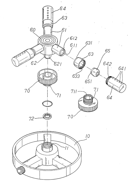
Please refer to Fig. 5. The present invention
includes a base seat 10, a sprinkling head 60 and a T-shaped
locking body 70. The base seat 10 is formed with a central
water-outgoing connector 11 having inner thread. The
sprinkling head 60 is a circular integral body, having three
radially extending water-outgoing passages 61 spaced by equal
angle and an insertion post 62 on bottom face for fitting into
the locking body 70. A lower end of the insertion post 62 is
flush with a lower end of a lower thread portion 71 of the
locking body 70. The lower end of the insertion post 62 is
formed with a small diameter portion 621 and the lower end of
the thread portion 71 of the locking body 70 is formed with a
69713-104
- CA 021661~7 1999-03-09
large diameter portion 711, whereby an annular space is
defined between the small diameter portion 621 and the large
diameter portion 711 for receiving a fusible ring 72. The
fusible ring 72 is fused by ultrasonic wave to associate with
the small diameter portion 621 of the insertion post 62 so as
to bind the insertion post 62 with the locking body 60. (The
fusible ring 72 is not fused with the lower end of the locking
body 70.) The thread portion 71 of the locking body 70 is
screwed into the central water-outgoing connector 11 of the
base seat 10 so that the water is conducted into the
sprinkling head 60 to flow out from the water-outgoing
passages 61 thereof.
A free end of each water-outgoing passage 61 is
formed with a large diameter hole 611 having a conic
peripheral wall 612 for receiving a valve post 621 of a hollow
ball valve 65. The valve post 651 of the ball valve 65 is
first passed through a tapered opening 631 of a cylindrical
valve sleeve 63 and then fitted into the large diameter hole
611 of the water-outgoing passage 61 and fused therewith by
ultrasonic wave. The tapered opening 631 of the valve sleeve
63 has an inclined inner peripheral wall face 632 for snugly
slidably abutting against the spherical face of the ball valve
65 in order to adjust the angle thereof. The tapered opening
631 also has an inclined outer peripheral wall face. The
valve sleeve 63 has an open end opposite to the tapered
opening, having an inner thread portion 633 to be screwed with
69713-104
X
' ~ CA 02l66l~7 l999-03-09
,~
a threaded neck portion 642 at one end of a cylindrical
sprinkling sleeve 64 formed with multiple sprinkling holes 641
by different angles. The end of the sprinkling sleeve 64 iS
formed with an inclined inner face 643 for snugly contacting
with the spherical face of the ball valve 65 to complete the
assembly as shown in Fig. 6.
Please refer to Figs. 7 to 7B. The water is
conducted through the water-outgoing connector 11 of the base
seat 10, the water-outgoing passages 61 of the sprinkling head
60, the ball valves 65 and the valve sleeves 63 and then
sprinkled out from the sprinkling holes 641 of the sprinkling
sleeves 64. At this time, the sprinkling head 60 iS rotated
to sprinkle the water onto the lawn in various directions. In
addition, the angle of the sprinkling sleeve 64 can be
adjusted through 360 degrees. Moreover, the inclined inner
peripheral wall face 632 of the tapered opening 631 of the
valve sleeve 63 and the inclined inner face 643 of the
sprinkling sleeve 64 are both slidable on the spherical face
of the ball valve 65. The conic peripheral wall 612 of the
20 water-outgoing passage 61 is substantially parallel to the end
face of the tapered opening 631 SO that the sprinkling sleeve
64 can be freely rotated. Accordingly, the three sprinkling
sleeves 64 can be freely adjusted in angle to sprinkle the
water in various directions.
The above description and drawings are only used to
illustrate one embodiment of the present invention and the
scope of the present invention should not be limited to the
69713-104
CA 02166157 1999-03-09
..~_.
embodiment. Any modification or variation derived from the
embodiment should fall within the scope of the present
invention.
69713-104