Note: Descriptions are shown in the official language in which they were submitted.
W095l037~ 2 ~ ~ 6 ~ ~ ~ PCT~S94/08013
FA~ N ":K MF~MR~12 WITH A DUAI, PURP08B COVER SHEET
CROSS-REFERENCE TO RELATED APPLICATIONS
This is a continuation-in-part application of
Serial No. 08/097,984 filed July 27, 1993.
TECHNICAL FIELD
The present invention relates to a fastener
arrangement having a dual purpose cover sheet.
BACKGROUND OF THE lNV~NllON
Interengaging and intermeshing fastener members
are useful in a variety of fields for fastening two
objects together. For example, hook and loop fasteners
typically include a first fastener member having a base
sheet and a plurality of hook members projecting
therefrom, and a second fastener member having a base
sheet and a plurality of loop members projecting
therefrom. When engaged, the hook members catch the loop
members to secure the two fastener members together. For
~uL~oses of the present invention, a fastener consists of
two fastener members, which may or may not be identical.
For example, a hook and loop fastener includes a hook
fastener member and a loop fastener member.
Exemplary of other fasteners of a similar type
are those shown in U.S. Patent Nos. 3,009,235, 4,454,183,
4,761,318, 4,775,310, 4,894,060, and 5,058,247, which
generally disclose a first fastener member having a base
sheet and a plurality of headed stems, and a second
fastener member having a base sheet and a plurality of
loop members. The respective fastener members are secured
together in much the same way as hook and loop fasteners,
whereby the headed stems engage or catch the loop members
to interengage the two fastener members.
Fasteners of the type described above are often
most useful when each fastener member is attached to a
surface of an object, so that the two objects may be
joined together by engaging the respective fastener
members. Examples of such applications include fasteners
fGr securing two portions of an article of clothing
together, or for securing a piece of trim to a surface.
SU~STITUTE SHEET ~RULE 26)
WOg5/037~ PCT~S94/08013
2 ~ 2-
One popular method of attaching the respective fastener
members to a surface is to provide a layer of pressure
sensitive adhesive on the base sheet, such that the
fastener member may be adhered to the surface of the
object by the pressure sensitive adhesive. Figure 1
illustrates such a conventional construction.
As shown in Figure 1, a fastener member lO
includes a base sheet 12 and a plurality of engaging
members 14 (in the form of hooks) that project from the
base sheet. Disposed on an opposite major surface of the
base sheet 12 is a layer of pressure sensitive adhesive
16, which typically includes a release liner 18 to protect
adhesive layer 16 prior to application of the fastener
member lO to a surface. To apply the fastener member lO
to a surface of an object, release liner 18 may be peeled
away from the base sheet to expose the adhesive layer 16.
A cover sheet is also provided to prevent the
engaging members from contacting and engaging with a
surface unintentionally. For example, hook members have a
t~n~ensy to engage with fabrics and textile materials, and
thus a fastener member including hook members may
unintentionally become attached to clothing or other
fabric prior to use, which is undesirable. A cover sheet
20, shown in Figure 1, covers the engaging members 14 and
thus aids in preventing unintentional engagement of the
engaging members with a surface prior to use. Thus, both
the cover sheet 20 and the release liner 18 must be
removed before the fastener member may be used.
A fastener of the foregoing construction has
been used in the field of carpet application.
Specifically, a fastener member may be used to anchor
carpet to a floor near a wall, or along a seam between
adjacent sections of carpet. Loop-like textile structures
are provided on the back of the carpet, and engaging
members are provided on the fastener member to engage the
loop-like structures and affix the carpet to the floor.
An example of a fastener used in conjunction
with carpet is shown in Figures 2A through 2D. Fastener
~U~ U~ S~l~E~ (RULE 26)
W095l037~ 2 ~ 2~ PCT~S94/08013
-3-
member 10 may be applied to a surface, such as a floor 30,
by removing the release liner 18 and pressing the adhesive
layer 16 into contact with the floor. Cover sheet 20 is
typically left attached to the engaging members 14 while
5 the carpet is being positioned and cut to size. Cover
sheet 20 thus prevents unintentional engagement between
the fastener member and the carpet while the carpet is
being manipulated in the vicinity of the fastener member.
Furthermore, the engaging members are protected from
contamination or damage due to exposure to people, dust,
- paint, fabrics, and the like. When the carpet 32 has been
cut and fit into place, cover sheet 20 may be peeled away
from fastener 10, allowing loop structures 34 of carpet 32
to engage the engaging members 14. Such a fast~n;ng
arrangement, in addition to affixing the carpet to the
floor, also allows the carpet to be peeled away from the
fastener member for cleaning or replacement. Although the
fastener product described above is widely used, it would
be desirable to reduce material costs inherent in the
product. Furthermore, because both the release liner and
the cover strip must both be removed prior to the
application of the fastener member, the application
process can be relatively time consuming, and therefore
expensive. It is also desirable to reduce waste
associated with all products that are used by consumers.
In view of ~hese concerns, it is desirable to provide an
inexpensive fastener member that is useful for
applications such as those described above.
SUMMARY OF THB lNv~NllON
A fastener arrangement is disclosed, comprising
a first fastener member, including a base sheet having a
first major surface, and a plurality of engaging members
attached to and projecting from the first major surface.
The fastener arrangement also includes a dual purpose
cover sheet having first and second major surfaces, the
first major surface including means for releasable
affixation to the first fastener member, and a second
SU~IT~ S~IEE~ (RI~E 26)
WO95/037~ PCT~S94/08013
21~2~ 4 ~
fastener member overlying the first fastener member. The
second fastener member includes a base sheet having first
and s~con~ major surfaces, a multiplicity of engaging
members attached to and projecting from the first major
surface, and an adhesive layer disposed on the second
major surface of said base sheet. The adhesive layer
releasably affixes the second fastener member to the
second major surface of said cover sheet.
Also provided is a method of providing a
fastener arrangement. The method comprises the steps of
- providing a first fastener member, including a base sheet
having first and second major surfaces, and a plurality of
engaging members attached to and projecting from the first
major surface; providing a dual purpose cover sheet having
first and second major surfaces; releasably affixing the
first major surface of the cover sheet to the first
fastener member; providing a second fastener member
including a base sheet having first and second major
surfaces, a plurality of engaging members attached to and
projecting from the first major surface, and an adhesive
layer disposed on the second major surface; and releasably
affixing the adhesive layer of the second fastener member
to the second major surface of the cover sheet.
BRIEF DESCRIPTION OF THE DRAWINGS
The present invention will be further explained
with reference to the appended Figures, wherein like
structure is referred to by like numerals throughout the
several views, and wherein:
Figure 1 is a sectional view of a fastener
member having a cover sheet and a release liner according
to the prior art;
Figures 2A through 2D are sectional views of
sequential steps in the process of applying a conventional
fastener member to a surface;
Figure 3 is a sectional view of a fastener
arrangement including a fastener member having a dual
purpose cover sheet according to the present invention;
E SHtET (RULE ~6)
WO95l037~ 2 ~ 6 ~ ~ ~ 5 PCT~S94/08013
-5-
Figures 4 through 7 are sectional views of
alternate embodiments of the fastener member and dual
purpose cover sheet of the present invention;
Figure 8 is a sectional view of an alternate
fastener arrangement according to the present invention;
Figure 9 is a perspective view of an exemplary
engaging member for use with the present invention;
Figure 10 is a top plan view of an another
al1:ernative embodiment of the fastener member and dual
purpose cover sheet according to the present invention;
- Figure 11 is a partial sectional view taken
across line 11--11 in Figure 10;
Figure 12 is a top plan view of a further
alt;ernative embodiment of the fastener member and dual
purpose cover sheet according to the present invention;
Figure 13 is a partial sectional view taken
across line 13--13 in Figure 12;
Figure 14 is a sectional view of another
alternative embodiment of the fastener member and dual
purpose cover sheet according to the present invention;
Figure 15 is a sectional view of a further
alt:ernative embodiment of the fastener member and dual
purpose cover sheet according to the present invention;
and
Figure 16 is a sectional view of an additional
alternative embodiment of the fastener member and dual
purpose cover sheet according to the present invention.
DET~Tr~n DESCRIPTION OF THE PREFERRED EMBODIMENTS
The present invention relates broadly to a
fa~tener member having a dual purpose cover sheet. The
dual purpose cover sheet functions both to be releasably
affixed to the engaging members and/or base sheet of a
first fastener member, and to be releasably affixed to a
pressure sensitive adhesive layer of a second, overlying
fastener member. Thus, the single cover sheet of the
present invention replaces the cover sheet and release
~1 ~B~TJTL~ ~ E S~E~ ~R~ILE 26)
W095/037~ PCT~S94/08013
2 ~ 6-
liner of the prior art, with a concomitant savings in
time, cost, and waste.
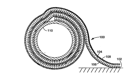
A preferred embodiment of the invention is
illustrated in Figure 3. Fastener member 100 is provided,
including a base sheet 102, a plurality of engaging
members 104, a layer of pressure sensitive adhesive 106,
and a dual purpose cover sheet 108. Each of the various
components will be described individually, followed by a
description of the overall structure, method of
construction, and operation of the present invention. The
numeric ranges for various values provided herein are
intended only to be illustrative, rather than limiting, of
the present invention.
~ase Sheet: The base sheet may be made from any
suitable material and in any suitable size. For example,
the base sheet may be made of polymer (e.g. polyethylene,
polypropylene, polyester, nylon, or rubber), textile
materials (e.g. cotton), or metal. The base sheet may be
extruded, woven, knitted, stitched, or made of a nonwoven
or other material, and may be made of two or more of these
and other materials (e.g. a laminate, or a blend). The
thickness of such a base sheet is preferably between 0.127
and 3.810 mm (0.005 and 0.150 in). The width of the base
sheet may be selected as desired, and widths in the range
of 0.635 to 365 cm (0.250 to 144 in) can be used.
The dimensions and material for the base sheet
are preferably selected so that the base sheet is
flexible, to facilitate attachment of the fastener member
to uneven surfaces. Furthermore, a fastener member having
a flexible base sheet may be coiled around a core 110 to
form a roll. However, rigid base sheets may also have
applicability in the context of the invention in, for
example, a stack of individual fastener members, as shown
in Figure 8.
The base sheet performs at least two functions.
First, the base sheet must hold the engaging members in
place, so that the engaging members are not detached from
the base sheet when the attached fastener members are
F S~T (Ps~LE ~6)
W095/037~ 2 ~ ~ 6 3 2 ~ PCT~S94/08013
-7-
separated from each other. Second, the base sheet must
provide a surface for receipt of the layer of pressure
sensitive adhesive. This surface may be smooth, striated,
knurled, wavy or of any other suitable topographical
5 design.
Engaqing Members: The engaging members of the
- present invention may be one or more of many different
types of such members. For example, the engaging members
may comprise hook portions, loop portions, structured
surfaces, headed stems, woven or nonwoven fibers, or any
- other suitable structures. Hook portions and loop
portions such as those disclosed in U.S. Patent Nos.
3,009,235, 4,761,318, 4,775,310, 4,894,060, and 5,067,210,
the contents of each of which is hereby incorporated by
reference, may have utility in this regard. Similarly,
structured surfaces such as those disclosed in U.S. Patent
Nos. 4,875,259, 5,088,164, and 5,196,266, the contents of
each of which is hereby incorporated by reference, are
exemplary, and may be useful in the context of the present
invention. Headed stems are disclosed in patents such as
U.S. Patent Nos. 3,138,841, 4,290,174, and 4,454,183, the
contents of each of which is hereby incorporated by
reference, and also may have utility in conjunction with
the present invention. Other suitable engaging members
are also contemplated.
The various engaging members are attached to,
bonded to, or formed from the base sheet, and should be
suitable for engaging an opposed fastener member, as
described previously. The opposed fastener may be
identical to or different from the subject fastener
member, depending on the relative configurations and
performance characteristics of each.
Adhesive Layer: The adhesive layer is disposed
on the major surface of the base sheet opposite the
engaging members. Adhesives that may be useful as the
adhesive layer in the present invention include pressure
sensitive and non-pressure sensitive adhesives. The
former class of adhesives are preferred, and are normally
T~TU, E S~ET t~ULE 26)
W095/037~ PCT~S94/08013
2 ~ 8- -
tacky at room temperature, and can be adhered to a surface
by the application of light finger pressure. The latter
class of adhesives include those that are solvent, heat,
or radiation activated. The adhesives may be based on,
for example, general compositions of polyacrylate,
polyvinyl ether, rubber (e.g. natural rubber), isoprene,
polychloroprene, butyl rubber, polyisobutylene, butadiene-
acrylonitrile polymer, thermoplastic elastomer, styrene-
butadiene polymer, poly-alpha-olefin, amorphous
polyolefin, silicone, ethylene-containing copolymer (e.g.
ethylene vinyl acetate, ethylene ethyl acrylate, ethylene
n-butyl acrylate, and ethylene methyl acrylate),
polyurethane, polyamide, epoxy, polyvinylpyrrolidone and
polyvinylpyrrolidone copolymers, polyesters, and mixtures
or copolymers of the foregoing. The adhesive layer may
also contain, for example, tackifiers, plasticizers,
fillers, antioxidants, stabilizers, pigments, curatives,
crosslinkers, solvents, and the like.
The thickness of the layer of pressure sensitive
adhesive may be selected as desired. Thicknesses in the
range of 0.0025 to 0.102 cm (0.001 to 0.040 in) have been
shown to have utility in the context of the present
invention, although other adhesive layer thicknesses may
also be used for certain applications. The adhesive layer
may be applied to the base sheet as known in the art. For
example, the adhesive may be applied to the base sheet by
solvent coating, extrusion (either separately from or
simultaneously with the base sheet), hot melt coating,
calendaring, curtain coating, gravure or pattern coating,
spray coating, lamination, pressure feed die coating,
knife coating, or by any other suitable t~r.hn; gue. It is
expressly contemplated that the adhesive layer can be
either continuous (such as a uniform layer) or
discontinuous (such as strips or bands, dots~ or another
patterned or random arrangement of discrete adhesive
portions).
Although a single layer of adhesive is
preferred, one or more additional layers may also be
T~ ~HEE~ (R~J~E 26)
W095/037~ 21~ ~ 3 2 ~ PCT~S94/08013
~ _g_
provided. These additional layers may be provided between
the adhesive layer and the base sheet (e.g. a primer layer
to facilitate bonding between the adhesive layer and the
base sheet), or may be applied over the adhesive layer
(e.g. an antistatic layer, a low adhesion backsize (LAB),
or a detackifying agent), or both. Of course, multiple
layers of adhesive are also contemplated.
The particular characteristics of the adhesive
layer may be selected to provide appropriate adhesion and
release characteristics. In carpet applications, for
- instance, it may be desirable to provide an adhesive layer
that is highly resistant to removal from the surface to
which the fastener member is attached. The
characteristics of various adhesives are well known, and
thus a suitable adhesive may be selected for a particular
application.
~ ual PurPose Cover Sheet: The dual purpose cover
sheet is preferably made of a thin, flexible material
having two opposed major surfaces. The first major
surface should be suitable for releasable affixation to
the engaging members and/or to the base sheet, and the
second major surface should be suitable for releasable
affixation to the pressure sensitive adhesive layer.
The first major surface of the dual purpose
cover sheet may comprise any suitable material that may be
releasably affixed to the engaging members and/or to the
base sheet. For example, if the engaging members comprise
hook structures, the first major surface may include a
plurality of loop structures for engagement with the hook
structures. As another example, the first major surface
may comprise a pressure sensitive adhesive to enable
adhesive affixation between the cover sheet and the
engaging members. Another alternative is to apply on the
first major surface an adhesive, such as a polymer having
a low melting point or a hot melt adhesive adapted for
transition from a first non-tacky state at room
temperature to a second tacky state when heated, and then
to heat the cover sheet until the adhesive becomes tacky.
~5TI~ SH~ET (RU~E 26)
WOg5/037~ PCT~S94/08013
2~ 25 ` -lo- ~
The warm and tacky adhesive is then applied to the
engaging members and/or to the base sheet where it then
cools and again becomes non-tacky. An advantage of using
an adhesive which is not tacky at room temperature is that
it permits more efficient handling of the cover sheet
during the prefabrication stages of the fastener member
when the cover sheet is applied to the engaging members
and/or base sheet and also during the application of the
fastener arrangement when the cover sheet is removed from
the engaging members and/or base sheet. Only when the
~ cover sheet is ready to be applied to the engaging members
and/or to the base sheet during the prefabrication stage
is the non-tacky adhesive heated to the point where it
tacky. The adhesive shown in Figure 8 is continuous on
the cover sheet and may be either tacky or non-tacky at
room temperature.
A further alternative is to affix the cover
sheet directly to the engaging members and/or to the base
sheet by fusing or bonding. As shown at 161 in Figures lO
and 11 and as further explained in Example Six ultrasonic
bonding is one method of attaching the cover sheet to the
engaging member or as shown at 161' in Figure 15 to the
base sheet. Other methods which utilize heat to melt or
fuse the cover sheet to the engaging members include
dielectric bonding, radio frequency bonding and heat
bonding. Ultrasonic bonding uses high frequency sound
waves which, when directed into the cover sheet and
engaging members and/or base sheet, generate heat by
causing ultrasonic vibrations in the materials and thereby
fuse or melt the cover sheet and engaging members and/or
base coat to each other. Ultrasonic bonding works best
when the cover sheet and engaging members are constructed
of similar materials. Ultrasonic bonding has the
advantage of eliminating an otherwise necessary adhesive
thereby saving material costs.
The means for releasably affixing the cover
sheet to the engaging members may be continuous (a uniform
arrangement of loop members or uniform adhesive layer, for
T~ T~ Sl~ET (R~ 26)
W095/037~ ~ ~ 6 ~ 3 2 ~ PCT~S94/08013
-11-
example) or discontinuous (narrow bands or dots of
adhesive, discrete sections of loop members, ultrasonic
weld or bond patterns, for example). Figures 12 and 13
illustrate a fastener member in which the cover sheet has
- 5 an adhesive dot coating 163 for affixation to the engaging
members as will be further explained in Example Seven. If
an adhesive is used to releasably engage the cover sheet
to the engaging member, then it is preferable, for the
reasons mentioned above, to use an adhesive which is not
tacky at room temperature but which becomes tacky after
heating.
Figure 14 illustrates an embodiment of the
fa~tener arrangement in which the cover sheet is attached
to the lateral edges of the base sheet and also to the
engaging members using an adhesive such as a polymer
ha~ing a low melting point or hot melt adhesive which has
a first non-tacky consistency at room temperature and a
second tacky consistency when heated. In this embodiment
no engaging members are provided at the lateral edges of
the base sheet 162 to permit the releasable affixation of
the cover sheet thereto.
Figure 15, as mentioned above, illustrates an
embodiment of the fastener arrangement in which the cover
sheet is attached to the lateral edges of the base sheet
and also to the engaging members using a series of
ultrasonic bonds along the lateral edges of the base
sheet. As with the embodiment in Figure 14, no engaging
members are provided at the lateral edges of the base
sheet 162 to permit releasable affixation of the cover
she~et thereto.
Figure 16 illustrates an embodiment of the
fastener arrangement in which the lateral edges of the
cover sheet is attached to the lateral edges of the base
sheet using a mechanical interlock of the type described
in W.S Patent No. 5,088,164, which includes a pair of
intermeshable closure members. Other mer-hAnical interlock
m~çl~A~;~ms which may used include, for example, those
described in U.S. Patent Nos. 5,138,750; 5,135,909;
TlJTE ~HE~ ULE 26)
WOg~/037~ 2 ~ 2 ~ PCT~S94/08013
-12-
5,056,933; 5,067,~22; 5,066,444; and 5,181,461 which are
hereby incorporated by reference.
Although Figures 14-16 illustrate the cover
sheet attached directly to a top surface of the base sheet
and/or to the engaging members it is within the intended
scope of the present invention that the cover sheet may be
attached to any selected portion of the base sheet and/or
engaging members. For example, the cover sheet may be
releasably attached to the side edges of the base sheet or
it may be wrapped around the side edges and releasably
attached to the major surface of the cover sheet opposite
the engaging members.
The second major surface of the dual purpose
cover sheet is adapted for releasable engagement with the
pressure sensitive layer described above. The second
major surface may comprise, for example, a release coating
such as silicone, an LAB coating (such as that described
in U.S. Patent No. 2,532,011 (Dahlquist et al.)), a plasma
coating, a Teflon~ coating, a structured surface, a low
energy polymeric surface such as polyethylene,
fluorocarbon additives, or no coating or structure at all.
Again, these and other release features of the second
major surface are preferably continuous over the area of
the surface.
The ~;~en~ions of the dual purpose cover sheet
may be selected to suit the particular application. It is
preferred that the dual purpose cover sheet be
approximately 0.012 to 1.78 mm (0.0005 to 0.070 in) thick,
and that the cover sheet be at least as wide as the wider
of the pressure sensitive adhesive layer and the plurality
of engaging members. For carpet fastening applications,
the dual purpose cover sheet is preferably thin, flexible,
and tear resistant, so that the cover sheet may be
withdrawn through a thin seam between sections of carpet,
or along a wall. Furthermore, the adhesion between the
cover sheet and the engaging members should be sufficient
to insure that the cover sheet is not inadvertently peeled
away from the fastener.
Sll~TIT~)TE SHEET ~Rl~L~ 26)
W095/037~ 2 ~ ~ ~ 3 2~ PCT~S94/08013
-13-
Suitable materials for the dual purpose cover
sheet may include, but are not limited to, treated or
unt:reated paper (e.g. crepe, rope tissue, repulpable
tissue, and kraft), woven fabric (e.g. cotton, rayon,
- 5 polyester, glass, and nylon), polymeric film (e.g.
cellophane, acetate, polyester, vinyl, polyvinyl chloride,
poly~ylene, polyethylene, and polyimide), nonwoven
fabric, foil (e.g. aluminum, stainless steel, and lead),
foam (e.g. open and closed cell polyethylene, polyvinyl
chloride, polyurethane, and polychloroprene), rubber (e.g.
neoprene), metallized film, or combinations or laminates
of the foregoing. The cover sheet may also inçlude
fib~ers, fillers, plasticizers, pigments, stabilizers,
antioxidants, or mixtures thereof. The cover sheet may
additionally bear a primer layer, or be surface treated
(e.g. corona discharge treated) to promote adhesion of
other constituents to it. Alternatively or additionally,
the cover sheet may undergo an orientation processing step
to improve its tensile strength characteristics, or be
coated with an LAB to prevent bonding or transfer of the
adhesive. The LAB may be selected to facilitate removal
of the fastener member from the dual purpose cover sheet,
and may not be necessary for some adhesives. Also, an
antistatic agent may be incorporated into the cover sheet,
to ~revent accumulation of static electricity on the
sheet.
It should be noted that in the preferred
embodiment, the characteristics of the dual purpose cover
sheet are selected so that the cover sheet remains affixed
to the engaging members and/or to the lateral edges of the
base sheet of the underlying fastener member, rather than
to 1_he adhesive layer of the overlying fastener member,
when the two fastener members are peeled apart. That is,
the cover sheet should preferably release from the
pressure sensitive adhesive layer and remain attached to
the engaging members and/or the base sheet of the
underlying layer of the fastener member. Stated yet
anot:her way, the adhesion force between the cover sheet
T~TU~E ~H~T (RU~ 26)
WO95/037~ ~ PCT~S94/08013
-14-
and the layer of pressure sensitive adhesive is preferably
less than the affixation force between the cover sheet and
the engaging members of an adjacent fastener member. For
example, a combination of adhesive and cover sheet may be
selected such that the adhesive layer separates from the
underlying cover sheet at a force of 24.6 g/cm width
(0.138 lb/in width), and the cover sheet separates from
the engaging members at a force of 70 g/cm width (0.38
lb/in width). These illustrative disengagement forces
were measured on a fastener member of the construction
~ described below in Example one.
The force required to separate the fastener
member from the underlying dual purpose cover sheet may
also be greater than the force required to separate the
cover sheet from the underlying engaging members. In the
case of the construction shown in Figure 3, using a
fastener and cover sheet such as that described in Example
Five, the force required to separate the fastener member
and adhesive layer from the cover sheet was approximately
258 g/cm width (1.44 lbs/in). The force required to
separate the cover sheet from the underlying engaging
members was approximately 20.9 g/cm width (0.12 lbs/in).
However, because the fastener member was wound in a coil,
the tensile forces in the cover sheet prevented the cover
sheet from being lifted away from the engaging members
when the overlying fastener member was peeled from the
roll. Thus, the relationship of the two force levels
(between fastener member and cover sheet, and between
cover sheet and engaging members) may be selected as
desired.
Various embodiments of the inventive fastener
member are illustrated in Figures 4 through 7. Figure 4
shows an embodiment wherein the engaging members comprise
a plurality of loop structures 120, which are attached to
a base sheet 122 having a layer of pressure sensitive
adhesive 124 disposed on the opposite surface. Dual
purpose cover sheet 126 includes a plurality of hook
~STI~I~TE ~ T (RIJLE ?6)
W095l037~ ~ ~ ~ 6 3 ~ ~ PCT~S94tO8013
-15-
structures 128 adapted for releasable interengagement with
the loop structures.
Figure 5 shows an embodiment wherein the
engaging members comprise a structured surface 130, which
- 5 is attached to a base sheet 132 having a layer of pressure
sensitive adhesive 134 disposed on the opposite surface.
Although structured surface 130 and base sheet 132 are
shown as being discrete components, they could instead be
unitary. Dual purpose cover sheet 136 includes an
opposed, matching structured surface 138, which is adapted
to intermesh with structured surface 130 to secure the
cover sheet. The respective structured surfaces may have
one of many different patterns, which need not necessarily
match each other.
The embodiments shown in Figures 6 and 7 include
engaging members that are generally shaped as headed stems
140" which each include a stem 142 that projects from base
sheet 144, and a head 146 formed at the distal end of stem
142. A layer of pressure sensitive adhesive 145 is
provided on the opposite surface of base sheet 144. Heads
146 may be hemispherical, conical, or some other suitable
shape, as known in the fastener art. The dual purpose
cover sheet may include loop structures 148 anchored to a
base sheet 150, as shown in Figure 6, or mating headed
stems 152 anchored to a base sheet 154, as shown in Figure
7.
The dual purpose cover sheet of the present
invention has primary, although not exclusive,
applicability to fastener members provided in roll form,
as shown in Figure 3. In the context of the embodiment
shown in Figure 3, a first fastener member and a second
fastener member may be spaced portions of a unitary,
longitll~;n~lly extending fastener member, rather than
individual, discrete fastener members. Other fastener
arrangements, such as the stack arrangement shown in
Figures 8 and 10-16, with the dual purpose cover sheet 160
disposed between adjacent fastener members 162, are also
included within the scope of the present invention.
~U~T~Tll~E SHt~T (~ULE 26)
W095/037~ PCT~S94/08013
2 ~ 16- ~
The construction and operation of the present
invention will be bettèr understood with reference to the
following Examples.
Example ~ne
A fastener member was produced by the process
described in U.S. Patent No. 4,894,060 (Nestegard). Both
the base sheet and the engaging members of the fastener
member comprised a pol~Lo~ylene copolymer resin,
available from the Shell Chemical Comr~ny of Houston,
Texas, under the designation SRD 6-166. The b~se sheet
measured approximately 100 mm (4 in) wide, and 0.18 mm
(0.007 in) thick, and included a plurality of T-shaped
engaging members that projected from the base sheet. Each
T-shaped engaging member, an example of which is shown in
Figure 9, measured approximately 0.254 mm (0.010 in) high,
and the engaging members were regularly spaced at a
density of approximately 66 per square cm (425 per square
inch). A layer of hot melt coated pressure sensitive
adhesive approximately 0.254 mm (0.010 in) thick was
extruded by a single screw extruder onto the base sheet on
the major surface opposite the engaging members, at a
temperature of approximately 154.5 C (310 F). The hot
melt adhesive used was a Kraton~ styrene-butadiene-styrene
rubber-based adhesive, comprising the following elements:
Material % (bY weiqht) Available Throuqh
Kraton~ 1118 rubber 19.8% Shell Chemical Co.
(Houston, TX)
Solprene~ 1205 Rllhh~r 20.8% Housemex, Inc.
(Houston, TX)
Piccolyte~ A135 Resin 48.3% Hercules, Inc.
(Brunswick, GA)
Shellflex~ 371 Oil 10.1% Shell Chemical Co.
(Houston, TX)
Irganox~ 1076 Antioxidant 1.0% Ciba Giegy Indus.
Chem. (McIntosh, TX)
The adhesive layer was allowed to cool at room
temperature. The dual purpose cover sheet was provided,
and was applied to the engaging members. The cover sheet
E ~ T ~f~lJ'LE 26)
W095/037~ 21~ ~ 3 ~5 PCT~S94/08013
-17-
was made of cast polypropylene and coated with a rubber
ba.sed adhesive on one side, for affixation to the engaging
members, and a silicone release agent on the other side,
to permit releasable engagement with the pressure
- 5 sensitive adhesive layer. The cover sheet measured
approximately 13.7 cm (4.5 in) wide, and 0.178 mm (0.007
in~ thick. A cover sheet of this type is available from
the ~ nne~ota M; n; ng and Manufacturing Company under the
designation KR-0261.
The fastener member was wound on a core having a
silicone release agent on the outer cylindrical surface,
suc:h that the adhesive layer adhered the fastener member
to the core. As the fastener member was wound on the
core, the cover sheet received the pressure sensitive
layer of the fastener member above it, as shown generally
in Figure 3. To unwind the roll, the fastener member
including the cover sheet was peeled from the core and
applied to a surface. To secure an object (such as
another fastener member, or a piece of carpet, for
example) to the fastener member mounted on the surface,
the cover sheet was removed to expose the engaging
members. The object could then be releasably attached to
the engaging members. The foregoing fastener arrangement
was found to perform satisfactorily.
ExamPle Two
A fastener member was prepared as described
above with reference to Example One, with the following
exceptions. The dual purpose cover sheet number KR-0261
was replaced by a dual purpose cover sheet including a
base sheet having protruding nylon tricot loop members,
available from the Guilford Mills Co. of GrPen~horo, North
Carolina, under the designation #31835. The opposite
(back) surface of the cover sheet was corona treated with
a 400 watt corona treatment station (operating at 13.5
amps, 75 volts, and a frequency of 27 kHz) while
travelling at 0.25 m/s (50 ft/min). Following the corona
treatment step, the back surface of the cover sheet was
coated with approximately 0.05 grains of silicone per
S(~ T~T~ ~H~E~ (~ULE 26)
2 ~
WOg5/037~ PCT~S94/08013
-18-
15,000 mm2 (24 in2), to facilitate release of an overlying
adhesive layer. The silicone was available from the Dow
Chemical Company of Midland, Michigan, under the
designations #7850 (97.2% by weight) and #7488 (2.8% by
weight). The silicone was cured at approximately 107 C
(225 F) for 15 seconds.
The cover sheet thus prepared was applied to the
fastener member described in Example One, with the loop
members of the cover sheet engaging with the engaging
members of the fastener member. The fastener member and
- dual purpose cover sheet were wound on a core in the
manner described in Example One, and were aged at room
temperature for three weeks. The fastener member was
found to perform satisfactorily.
It should be noted that the foregoing
construction may not be suitable for all applications,
because the cover sheet is highly permeable, which allows
air flow past the adhesive layer of the fastener member.
This air flow can cause some adhesives to lose tack, as is
known in the art. Thus, adhesives used with the foregoing
construction should be selected to be resistant to the
potentially deleterious effects of air flow.
Example Three
A fastener member was prepared as described
above with reference to Example One, with the following
exceptions. The KR-0261 dual purpose cover sheet was
replaced by a biaxially oriented polypropylene film tape
cover sheet. The tape cover sheet was prepared with a
pressure sensitive adhesive on one surface, for
application to the engaging members, and with an LAB coat
on the opposite surface, for application to the pressure
sensitive adhesive layer of an overlying fastener member.
A tape of such a construction is available from the
Mi ~n~Rota Mining and Manufacturing Company, under the
designation Highl ~n~ Brand Utility Box Sealing Tape #371.
The adhesive side of the tape cover sheet w~s
applied to the uppermost portions of the engaging members,
and thus the LAB side was presented for receipt of the
~'J~ iTUT~ E~ VLE 26~
WO9~/037~ 21 ~ ~ 3 ~ ~ PCT~S94/08013
--19--
pressure sensitive adhesive layer of an overlying fastener
member. The fastener member and the tape cover sheet were
thereafter wound on a core in the manner described in
Example One, and was aged for one week at room
te]nperature. The fastener member was difficult to unwind,
because of the hlgh adhesion between the pressure
- se~sitive adhesive layer of the fastener member and the
L~3 side of the tape cover sheet. It is believed that the
use of a less aggressive adhesive on the fastener member,
or a more effective LAB on the cover sheet, would result
- in better unw;n~; ng performance.
~xample Four
A fastener member was prepared as described
above with reference to Example One, with the following
exceptions. The KR-0261 dual purpose cover sheet was
replaced by a base sheet having loop members, comprising a
poly~o~ylene copolymer sheet with poly~ylene loop
members projecting therefrom. The overall thickness of
the cover sheet was 1.65 mm (0.065 in), including a base
sheet measuring approximately 0.051 mm (0.002 in) thick
and loop members measuring approximately 1.6 mm (0.063 in)
high. The density of the loop members was approximately
33 g/m2 (0.062 lb/yd2). A product of this general type is
particularly described in PCT Patent Publication No.
92J01401.
The surface of the cover sheet opposite the loop
members (the back surface) was corona treated with a 400
wa~t corona treatment station (operating at 13.5 amps, 75
volts, and a frec~uency of 27 kHz) while travelling at 0.25
m/s (50 ft/min). Following the corona treatment step, the
bac:k surface was coated with approximately 0.022 grains of
silicone per 15,000 mm2 (24 in2), to facilitate release of
an overlying adhesive layer. The silicone was available
from the Dow Chemical Company under the designations #7850
(97.2% by weight) and #7488 (2.8% by weight). The
silicone was cured at approximately 107 C (225 F) for 15
seconds.
ITUT~SHE~I (RUIE26)
WO95/037~ ~ ~ ~ 3 ~ l I PCT~S94/08013
-20-
The cover sheet thus prepared was applied to the
fastener member described in Example One, with the loop
members of the cover sheet engaging with the engaging
members of the fastener member. The fastener member and
dual purpose cover sheet were wound on a core in the
manner described in Example One, and were aged at room
temperature for three weeks. The fastener member was
found to perform satisfactorily.
~mPle Five
A fastener member was prepared as described
- above with reference to Example One, with the following
exceptions. The KR-0261 dual purpose cover sheet was
replaced by a biaxially oriented polyester film tape cover
sheet. The tape cover sheet was prepared with a pressure
sensitive adhesive on one surface, for application to the
engaging members, and with an LAB coat on the opposite
surface, for application to the pressure sensitive
adhesive layer of an overlying fastener member. A tape of
such a construction is available from the Minnesota Mining
and Manufacturing Company, under the designation #353.
The adhesive side of the tape cover sheet was
applied to the uppermost portions of the engaging members,
and thus the LAB side was presented for receipt of the
pressure sensitive adhesive layer of an overlying fastener
member. The fastener member and the tape cover sheet were
thereafter wound on a core in the manner described in
Example One, and was aged for one week at room
temperature. The fastener member was difficult to unwind,
because of the high adhesion between the pressure
sensitive adhesive layer of the fastener member and the
LAB side of the tape cover sheet. It is believed that the
use of a less aggressive adhesive on the fastener member,
or a more effective LAB on the cover sheet, would result
in better unwinding performance.
~mple Six
A fastener member was prepared as described
above with reference to Example One, with the following
exceptions. The dual purpose cover sheet number KR-0261
~U~TITl~T~ SH~ (RI~E 26)
W095/037~ 2 ~ ~ 6 ~ 2 ~ PCT~S94/08013
-21-
was replaced by a polypropylene liner having a thickness
of 0.127 mm (0.005 in). The polypropylene liner was
silicone coated on one side so that it acted as the cover
sheet. The non-silicone coated surface was placed face
down on the engaging members of the hook fastening member.
The hook fastening member was produced using a
- pol~p~o~ylene copolymer designated Shell 7C55H, available
from Shell Chemical Company, Houston, Texas. The non-
silicone side of the cover sheet was then ultrasonically
bonded to the hook fasten; ng members using a sonic horn
with the circular pattern shown in Figure 10. Although
the circular pattern was used other patterns, such as
lines adjacent the lateral edges of the cover sheet, may
also be used. Figure 11 illustrates the fusion between
the cover sheet and the fastening members wherein the
fasten;n~ members are deformed and fused to the cover
sheet. The ultrasonic bonding unit used was designated
Model# 8400, available from the Branson Sonic Power
Company, Danbury, Connecticut. The ultrasonic hon~ing was
performed using a pressure of 30 PSI, a weld time of 2
seconds and a hold time of 2 seconds.
After ultrasonic bonding of the cover sheet to
the engaging members the cover sheet was bonded well
enough so that the pressure sensitive adhesive of a second
hook fastening member could be applied on the silicone
release surface of the dual purpose cover sheet and then
removed without dislodging the cover sheet. The dual
purpose cover sheet however could be removed by hand to
expose the engaging members of the first hook fastening
mem~er. Other fusion or bonding methods wherein heat is
generated to melt or fuse the cover sheet to the engaging
member, although not tested, are contemplated and intended
to be within the scope of the present invention.
ExamPle Seven
A fastener member was prepared as described
above with reference to Example One, with the following
exceptions. The dual purpose cover sheet number KR-0261
was replaced by a polypropylene liner having a thickness
TI~ SffEET (RlJLE 26~
W095/037~ 2 1 ~ 6 3 ~ ~ - 22- PCT~S94/08013
of 0.127 mm (0.005 in). The polypropylene liner was
silicone coated on one side 50 that it acted as the cover
sheet. The non-silicone coated side of the cover sheet
was dot coated with 3M Jet-melt~ adhesive #3747 (available
from Minnesota Mining and Manufacturing Company, St. Paul,
~;n~fiota) using a 3M PolygunTM TC Hot Melt Applicator
(available from Minnesota Mining and Manufacturing
Company). The adhesive was dot coated using the pattern
shown in Figure 12. While the hot melt adhesive was still
warm and tacky the cover sheet was placed face down on the
~ engaging members of a hook fastening member of Example 6.
When cooled to room temperature the hot melt was not tacky
and the cover sheet was engaging to the fastening members.
Figure 13 illustrates the adhesive bond between the
fast~ni ng members and the cover sheet.
After bonding of the cover sheet to the engaging
members the cover sheet was bonded well enough so that the
pressure sensitive adhesive of a second hook fastening
member could be applied on the silicone release surface of
the dual purpose cover sheet and then removed without
dislodging the cover sheet. The,dual purpose cover sheet
however could be removed by hand to expose the engaging
members of the first hook fastening member.
The present invention has now been described
with reference to several embodiments thereof. It will be
apparent to those skilled in the art that many changes can
be made in the embodiments described without departing
from the scope of the invention. Thus, the scope of the
present invention should not be limited to the structures
described herein, but rather by the structures described
by the language of the claims, and the equivalents of
those structures.
Sl~ Tl}T~ S~EET (RULE 26)