Language selection

Search

Patent 2166417 Summary

Third-party information liability

Some of the information on this Web page has been provided by external sources. The Government of Canada is not responsible for the accuracy, reliability or currency of the information supplied by external sources. Users wishing to rely upon this information should consult directly with the source of the information. Content provided by external sources is not subject to official languages, privacy and accessibility requirements.

Claims and Abstract availability

Any discrepancies in the text and image of the Claims and Abstract are due to differing posting times. Text of the Claims and Abstract are posted:

  • At the time the application is open to public inspection;
  • At the time of issue of the patent (grant).
(12) Patent Application: (11) CA 2166417
(54) English Title: A MULTI-PAGE UNIT AND WRITING INSTRUMENT COMBINATION
(54) French Title: BLOC MULTI-FEUILLE AVEC INSTRUMENT D'ECRITURE
Status: Dead
Bibliographic Data
(51) International Patent Classification (IPC):
  • B43K 29/12 (2006.01)
  • B42D 3/12 (2006.01)
  • B42D 5/00 (2006.01)
  • B43K 23/00 (2006.01)
  • B43K 25/02 (2006.01)
  • B43K 29/087 (2006.01)
(72) Inventors :
  • ZOLAND, MARTIN (Australia)
(73) Owners :
  • ZOLAND, MARTIN (Australia)
(71) Applicants :
(74) Agent: OYEN WIGGS GREEN & MUTALA LLP
(74) Associate agent:
(45) Issued:
(86) PCT Filing Date: 1994-07-01
(87) Open to Public Inspection: 1995-01-19
Examination requested: 2001-07-03
Availability of licence: N/A
(25) Language of filing: English

Patent Cooperation Treaty (PCT): Yes
(86) PCT Filing Number: PCT/AU1994/000365
(87) International Publication Number: WO1995/001882
(85) National Entry: 1995-12-29

(30) Application Priority Data:
Application No. Country/Territory Date
08/087,921 United States of America 1993-07-06
08/263,053 United States of America 1994-06-21

Abstracts

English Abstract


A combination of a writing instrument (19) and a notepad (11) or calendar wherein the writing instrument can be easily attached to
and removed from the notepad or calendar. A through-hole (15) in the notepad or calendar is adapted to receive a pocket clip typically
found on many conventional pens. Preferably the clip has an upwardly curved end (31) to facilitate insertion of the clip into the hole,
especially where the notopad or calendar includes a number of sheets of paper requiring that the hole passes through each of the sheets. In
a preferred embodiment, the through-hole is located near an edge of the notepad or calendar. Thus, a pen or other writing instrument can
be secured to the notepad or calendar by inserting the clip through the hole.


French Abstract

Ensemble constitué d'un instrument d'écriture (19) et d'un carnet (11) ou d'un agenda, dans lequel l'instrument d'écriture peut facilement être attaché sur le carnet ou l'agenda et détaché de ce dernier. Un trou traversant (15) formé dans le carnet ou l'agenda est prévu pour recevoir une agrafe du type de celle qui existe sur beaucoup de stylos courants. L'agrafe comprend de préférence une extrémité (31) recourbée vers le haut qui facilite l'insertion de l'agrafe dans le trou, notamment lorsque le carnet ou l'agenda comporte un nombre de feuilles de papier tel que le trou doit traverser chacune des feuilles. Dans une forme de réalisation préférée le trou traversant est situé à proximité d'un bord du carnet ou de l'agenda. Ce système permet d'attacher un stylo ou tout autre instrument d'écriture sur le carnet ou l'agenda en introduisant l'agrafe dans le trou.

Claims

Note: Claims are shown in the official language in which they were submitted.


-6-
CLAlMS:

1. A multi-page unit and writing instrument combination, said multi-page unit
having a front side and a back side and a plurality of sheets of paper, said writing
instlument including a body and a clip, said clip having proximal and distal ends, said
combination comprisig:
a through-hole disposed on said multi-page unit, said through-hole for receivingsaid clip of said writing imstrument such that the distal end of the clip is insertable
through the hole, such that the distal end of the clip lies against the back side of said
multi-page unit and the body of the writing instrument lies against the front side of said
multi-page unit.

2. A multi-page unit and writing instrument combination according to claim 1,
wherein said through-hole is located substantially midway along an edge of said
multi-page unit.

3. A multi-page unit and writing instrument combination according to claim 1,
wherein said through-hole is reinforced with a means for stiffening.

4. A multi-page unit and writing instrument combination according to claim 1,
wherein said distal end of said clip curves in a direction away from the body of the
writing instrument.

5. A multi-page unit and writing instrument combination according to claim 1,
wherein said multi-page unit comprises a plurality of paper pages.

6. A multi-page unit and writing instrument combination according to claim 5,
wherein said multi-page unit further comprises a cardboard back.

7. A multi-page unit and writing instrument combination, said multi-page unit
having a front side and a back side and a plurality of sheets of paper, said writing
instrument including a body and a clip, said clip having proximal and distal ends, said

- 7 -

combination comprising:
a through-hole disposed on said multi-page unit, said through-hole for receivingsaid clip of said writing instrument such that the distal end of the clip is insertable
through the hole such that the distal end of the clip lies against the back side of said
multi-page unit and the body of writing instrument lies against the front side of said
multi-page unit; wherein said through-hole is disposed substantially midway along an
edge of said multi-page unit, said through-hole is reinforced with a means for stiffening,
and said distal end of said clip curves in a direction away from the body of the writing
instrument.

8. A multi-page unit and writing instrument combination, said multi-page unit
having a front side and a back side and a plurality of sheets of paper, said writing
instrument including a body and a clip, said clip having proximal and distal ends, said
combination comprising:
a through-hole disposed on said multi-page unit, said through-hole for receivingsaid clip of said writing instrument such that the distal end of the clip is insertable
through the hole such that the distal end of the clip lies against the back side of said
multi-page unit and the body of writing instrument lies against the front side of said
multi-page unit; wherein said multi-page unit includes a plurality of paper pages and a
cardboard back, said through-hole is disposed substantially midway along an edge of said
multi-page unit, said through-hole is reinforced with a means for stiffening, and said
distal end of said clip curves in a direction away from the body of the writing instrument.

9. The combination defined by claim 1 wherein said multi-page unit is a notepad.
10. The combination defined by claim 2 wherein said multi-page unit is a notepad.

11. The combination defined by claim 3 wherein said multi-page unit is a notepad.

12. The combination defined by claim 4 wherein said multi-page unit is a notepad.

13. The combination defined by claim 5 wherein said multi-page unit is a notepad.

- 8 -
14. The combination defined by claim 6 wherein said multi-page unit is a notepad.

15. The combination defined by claim 7 wherein said multi-page unit is a notepad.

16. The combination defined by claim 8 wherein said multi-page unit is a notepad.

17. The combination defined by claim 1 wherein said multi-page unit is a calendar.

18. The combination defined by claim 2 wherein said multi-page unit is a calendar.

19. The combination defined by claim 3 wherein said multi-page unit is a calendar.

20. The combination defined by claim 4 wherein said multi-page unit is a calendar.

21. The combination defined by claim 5 wherein said multi-page unit is a calandar.

22. The combination defined by claim 6 wherein said multi-page unit is a calendar.

23. The combination defined by claim 7 wherein said multi-page unit is a calendar.

24. The combination defined by claim 8 wherein said multi-page unit is a calendar.

25. The combination defined by claim 1 wherein said multi-page unit further
comprises a cardboard back and through-hole passes only through said cardboard back.

26. The combination defined by daim 6 wherein said through-hole passes only
through said cardboard back.

27. The combination defined by claim 8 wherein said through-hole passes only
through said cardboard back.

28. A multi-page unit and writing instrument combination, said multi-page unit


- 9 -
having a front side and a back side and a plurality of sheets of paper, said writing
instrument including a body and a clip, said clip having proximal and distal ends, said
combination comprising:
a through-hole disposed on said multi-page unit, said through-hole for receivingsaid clip of said writing instrument such that the distal end of the clip is insertable
through the hole, such that the distal end of the clip lies against the front side of said
multi-page unit and the body of the writing instrument lies against the back side of said
multi-page unit.

29. A multi-page unit and writing instrument combination, said multi-page unit
having a front side and a back side and a plurality of sheets of paper, said writing
instrument including a body and a clip, said clip having proximal and distal ends, said
combination comprising:
a through-hole disclosed on said multi-page unit, said through-hole for receiving
said clip of said writing instrument such that the distal end of the clip is insertable
through the hole such that the distal end of the clip lies against the front side of said
multi-page unit and the body of writing instrument lies against the back side of said
multi-page unit; wherein said through-hole is disposed substantially midway along an
edge of said multi-page unit, said through-hole is reinforced with a means for stiffening,
and said distal end of said clip curves in a direction away from the body of the writing
instrument.

30. A multi-page unit and writing instrument combination, said multi-page unit
having a front side and a back side and a plurality of sheets of paper, said writing
instrument including a body and a clip, said clip having proximal and distal ends, said
combination comprising:
a through-hole disposed on said multi-page unit, said through-hole for receivingsaid clip of said writing instrument such that the distal end of the clip is insertable
through the hole such that the distal end of the clip lies against the front side of said
multi-page unit and the body of writing instrument lies against the back side of said
multi-page unit; wherein said multi-page unit includes a plurality of paper pages and a
cardboard back, said through-hole is disposed substantially midway along an edge of said

- 10 -
multi-page unit, said through-hole is reinforced with a means for stiffening, and said
distal end of said clip curves in a direction away from the body of the writing instrument.

31. The combination defined by claim 28 wherein said multi-page unit further
comprises a cardboard back and said through-hole passes only through said cardboard
back.

32. The combination defined by claim 29 wherein said multi-page unit further
comprises a cardboard back and said through-hole passes only through said cardboard
back.

33. The combination defined by claim 30 wherein said through-hole passes only
through said cardboard back.

34. A multi-page unit and writing instrument combination, said multi-page unit
having a front side and a back side and a plurality of sheets of paper, said writing
instrument including a body and a clip, said combination comprising:
two pairs of slits disposed on said multi-page unit, said two pairs of slits forreceiving said clip of said writing instrument such that a first end of the clip is insertable
through one of said two pairs of slits and a second end of the clip is insertable through
the other of said two pairs of slits.

35. The multi-page unit defined by claim 34 wherein said multi-page unit includes
a cardboard back and said two pairs of slits pass through said cardboard back.

36. A multi-page unit and writing instrument combination, said multi-page unit
including an opening and said writing instrument including clip means for insertion into
said opening so as to cause said writing instrument to engage said multi-page unit.

37. A method of attaching a writing instrument to a multi-page unit, including
inserting clip means of said writing instrument into an opening of said multi-page unit
thereby causing said clip means to engage said multi-page unit.

Description

Note: Descriptions are shown in the official language in which they were submitted.


WO 95/01882 PCT/AU94/00365


A MULII-PAGE UNIT AND WRlTlNG INSTRUMENT COMBINAT~ON


BACKGROUND OF THE INVENTION
1. Field of the Illv~lllion

The present invention relates to a multi-page unit and writing i~llulllc~l
combinAtion, and, in particular, to ~-ot~pA~le and rAl~ with a writing i,lsllullle
15 Attar hr"l

2. Dc~ t;~ ~ of the Prior Art and Related Lfo....~ n

Quite often, people who attend l~ s ..-P~I;.~ or school remPmb~-r to bring a
20 llol~pad but s ...~ es forget a writing ill~llulllenl. Th~,lcfolc, many te~hniques have
been devised to co~ P~ one with the other. Where the l~o~A~l is part of a folder, U.S.
Patent No. 5,011,188 to Zoland et al. discloses a pen and folder combi.~AI ;o" The folder
has a hole ~ ose~ through both the front and back covers in an aligned o. :e.~l I ion A
clip typically found on a pen can thus be illsell~d into the hole to eim~ eo~ y secure
25 the pen to the folder and to dasp the covers of the folder togPthPr. Similar is U.S. Patent
No. 5,190,317 to Zoland which has a hole di~osed through just one cover of a folder
such that a clip typically found on a pen can thus be hlse.hd into the hole to
.~imlllt~ncously sccure the pen to the folder.

~imilz-rly, it is frequently desirable to have a pen or other writing i~llul,le~l
readily ~ ssiblc to a flat wall cZll~n~ r in order to make ~...ol;~;on~ thereon such as
birthdays, social events and the like.

WO 95/01882 PCT/AU94/0036


S~ IARY OF THE INVENTION

The present invention provides a novel combination of a writing instrument and
a notepad or c~lentlAr wL~cill the writing hl~ can be easily ~tt~çh~ to andS removed from the nntep~d or c~lPn-lAr. In a preferred emb~imrnt, the present invention
provides a through-hole located near an edge of the n-)tepAd or r~lPnrl~r The
through-hole is AdArted to receive a pocket clip typically found on many col.vclllional
pens, Alth- -gh, preferably, the clip has an upwardly curved end to fArilitAte insertion of
the clip into the hole, esper;~lly where the n<-tep~cl inrllldes a number of sheets of paper
10 ~ ;"g, in one embo~iimPnt~ that the hole pass through each of the shcets. Thus, a pen
or other writing ihl~lulllelll can be secured to the n~ tepA~l or c~len~lAr by inserting the clip
through the hole.

The plcîcl~.d embo~ provide a s1lperior mrth~l of holding the pen to the
15 lloh pad than the cc,llv~ ;onAl prArtire of simply clipping the pen to an edge of the
..ot~ l since the hole serves to limit muvclll~ of the writing iL~llullle.ll, reduçing the
likelihood of the writing i~ uluelll l~o..~ g dislodged. .CimilArly, with respect to a
r~lPn-l~r-writing hl~llull.e ~t combi~ ioll, the present invention is ~ ;or to clipping thc
pen to an edge of the c~lrT-~lAr or ;,1 .;ug the pen to the c~ Ar by a string since the
20 pen would be free to swing aS people waLk past the r~lrnrl~r~ possibly e~lxi.~g m~rking.c
on the wall on which the c~l~ntlAr is hAn~ing Further, the hole/clip combination can be
shaped so that there is a snug fit ~l..~en the clip and the hole thereby ...i..i...ic;..g the
chance of the clip "~ lly slipping out of the hole.

Accol.lillgly, the present invention provides a simplc .. Pr~ i.C.~ for AttA~'hing a
writing instrument to a noteE~ad or c~lenrl~r~ and a simple ~hi~for removing thewriting hl~llulnell~ from the ..olgpad or c~lentl~r.

BRIEF DESCRIP~ON OF THE DRAW~NGS
~ cr~ d embc~ x of the present invention are h~ l~ihlarl~,l rlesrrihe~l, by way
of example only, with reference to the accompallyi,lg dlawill~s, wherein:

WO g5/01882 PC~IAU94/00365


Figure 1 is a ~ ;ve view of a pre~,l~,d PnnhotlimPnt of thc present invention,
Wi~lCh~ a pen is clipped to a n~-tepA~l by hlse.ling thc clip of the pen through the
through-hole;
Figure 2 is a profile view of the notep~l and pen combination shown in Figure
S 1 clearly ~epicting thc clip and its rel~tiollchip to the l-nl~,p~d and the through-holc after
insertion;
Figure 3 is a ~-x~l;v~ view of an ~lte~n~te embodi~elll of the invention
wLe.tm the pen is clipped di~ lly to a ca~ oald or other l:~A~ g used to hold the
.~ot~ad on the ..nt~,pad side of the bA~ ;"~"
Figure 4 is a ~-~-I;~c view of an ~ltrrn~te embodiment of the ilvc;l-liol-
WhC1eL1 the pen is clipped dil~,clly to a c~dboard or other l~A.~ g used to hold the
notepA~1, on the side opposite the notepAd side of the bAr~ g;
Figure 5 is a side elevation view of a writing ill~lluLue.ll having an ~Itern~teclipping ...crl~A.~ for ~tt~l....r~.l to the ..ot~A~i; and
Figure 6 is a top plan of an AltPrnAte emboAim~nt of a .. nl~AA and writing
LIDI1 Ulll~,11l COm~ dtiOn.

DETAILED DESCR~ ON OF THE INVENTION

In the following ~lcs~ )n, ~Ull~C~us details such as s~~ mZltP.ri~lc and
confi~ .,.ti~ c arc set forth in order to provide a more complelt; .~ u~ g of the
present invention. However, the present invcntion can be pnctir~l without those specifi~
details. In other i.~ s, well-known el~ are not dçsrribe~l explicitly so as not
to obscule the present h.~lllio
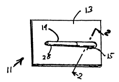
Figure 1 shows a ~l~ll~ embodiment of the present invention. A ...~
is shown having a front 13 and an idçntir~l back which is not shown. The back may be
made of a stiff cardboard m~t-ri~l or it may simply be the last page of the notepad The
noter~l in~ dP,s a number of paper pagec and the optional ~.l~d back 14. Instead30 of a n-tep~-l, a wall e~l~ntl~r or other item having a rclatively small number of pages
having a ~ont and a back, with or without an optional cal.ll~ald back could also be used
to implem~.nt the invention.

wo 95/0l882 ~) PCT/AUgllon365


Unique in the present invention is a through-hole 15 disposed through the pages
of the notepad or c~ql~ontlqr and the optionql cardboard back 14, or as shown in Figure 3,
through just the c~.ll,Oa,.l back, which in the Figure 3 embo~1impntis not optional. Thc
purpose of the through-hole lS is to provide a point of qttq.~hmPnt for a writing
5 iusll.lluent 19. As shown in the pe,~pGc~;ve view of Figure 1 and Figure 3, the writing
iu~llumelll 19, here a pen, is coupk~ to the notepad 11 via the through-hole 15. The
coupling is ~qcrn...pliche~1 by a pocket clip 23, found on almost all cou~ nql pens and
mqrkp,~

Figure 2 provides a side view of the nstepq.~l and pen combination illnstrqtP~d in
Figure 1. As is f1P.t~ilPd in the drawing, the clip 23 of the writing iu~ lùelll 19 passes
through the through-hole 15. A distal end 28 of the writing i~llunlenl 19 lies against
the surface of the paper portion of~ p~d 13, or as sho~vn in the Figure 3 embo~im~nt,
against the surface of the cal.ll,o~ b~ L ;.~g 14. A ~lv~hl~al end 25 of the clip 23 rides
15 at the lip of the through-hole 15. To fqrilit,te insertion of the clip 23 into the
through-hole 15, çsper;qlly where the notep~qd in~lucles a mlmh~r of pages and/or a
car~boa~ back making the ~-- t~d relatively thick, the clip may be confi~lred to include
a portion 31 at the end of the clip which curves upward, away from the body of the
writing iu~llulu~ 19.
To implov~; durability, the present invention provides that the through-hole 15
may be l~ulrol~d with another layer of n~tçri~l 35 if ~r~ss~ or ~1 ;rr~ A with a metal
or plastic ring. Other techni~lues for stren~ g the through-hole 15 known in the art
can be applied here as well.
Figure 4 is similar to Figure 3 excepting that the writing iL~IIuu~ is dispose~
on the side of the b~cking opposile from the side used to hold the notepad

Figure S is an illl~ctr~tion of a mo lifi~d writing hl~llu~ t which instead of a clip
30 which is generally parallel to the body of the pen as best seen in Figure 2, has a clip
which is ~:nrr~lly perprn~ r to the body of the wIiting hlslluuu~lll as shown in Figure
S with two wing portions e~ g from the body of the writing hl~llullleùl. In thc

Wo 95/01882 PCTIAU94/00365
_ 5 _

Figure S cmbo~ r~, instead of a through-hole 15, thc c~dl~oa,d b~ in~, if present,
or paper, if there is no bA~L ;,~g, inrludes two pairs of slits or cuts 35a and 35b into which
thc two wing portions of clip 33 are hls~lled as shown in Figure 6.

Naturally, the through-hole can be located on various other locations of the
notep~d with the ~coc;~ d writing in~ co....ec~.,cl in various o,;r..~ . These
v ;il;o~ are within the scopc and spirit of thc prcscnt invcntion as rlcfinr(l in the
~ pC~ ~ claims.


Representative Drawing
A single figure which represents the drawing illustrating the invention.
Administrative Status

For a clearer understanding of the status of the application/patent presented on this page, the site Disclaimer , as well as the definitions for Patent , Administrative Status , Maintenance Fee  and Payment History  should be consulted.

Administrative Status

Title Date
Forecasted Issue Date Unavailable
(86) PCT Filing Date 1994-07-01
(87) PCT Publication Date 1995-01-19
(85) National Entry 1995-12-29
Examination Requested 2001-07-03
Dead Application 2003-07-02

Abandonment History

Abandonment Date Reason Reinstatement Date
2000-07-04 FAILURE TO PAY APPLICATION MAINTENANCE FEE 2000-08-25
2002-07-02 FAILURE TO PAY APPLICATION MAINTENANCE FEE

Payment History

Fee Type Anniversary Year Due Date Amount Paid Paid Date
Application Fee $0.00 1995-12-29
Maintenance Fee - Application - New Act 2 1996-07-01 $50.00 1996-05-10
Maintenance Fee - Application - New Act 3 1997-07-02 $50.00 1997-06-27
Maintenance Fee - Application - New Act 4 1998-07-02 $50.00 1998-05-19
Maintenance Fee - Application - New Act 5 1999-07-01 $75.00 1999-06-02
Reinstatement: Failure to Pay Application Maintenance Fees $200.00 2000-08-25
Maintenance Fee - Application - New Act 6 2000-07-04 $75.00 2000-08-25
Maintenance Fee - Application - New Act 7 2001-07-03 $75.00 2001-06-20
Request for Examination $200.00 2001-07-03
Owners on Record

Note: Records showing the ownership history in alphabetical order.

Current Owners on Record
ZOLAND, MARTIN
Past Owners on Record
None
Past Owners that do not appear in the "Owners on Record" listing will appear in other documentation within the application.
Documents

To view selected files, please enter reCAPTCHA code :


To view images, click a link in the Document Description column. To download the documents, select one or more checkboxes in the first column and then click the "Download Selected in PDF format (Zip Archive)" or the "Download Selected as Single PDF" button.

List of published and non-published patent-specific documents on the CPD .

If you have any difficulty accessing content, you can call the Client Service Centre at 1-866-997-1936 or send them an e-mail at CIPO Client Service Centre.


Document
Description 
Date
(yyyy-mm-dd) 
Number of pages   Size of Image (KB) 
Representative Drawing 1998-07-20 1 3
Cover Page 1996-04-25 1 17
Abstract 1995-01-19 1 45
Description 1995-01-19 5 196
Claims 1995-01-19 5 223
Drawings 1995-01-19 3 25
Assignment 1995-12-29 4 189
PCT 1995-12-29 9 411
Prosecution-Amendment 2001-07-03 1 49
Correspondence 1996-04-01 5 179
Prosecution-Amendment 2001-11-07 1 31
Fees 1997-06-27 1 42
Fees 1996-05-10 1 49