Note: Descriptions are shown in the official language in which they were submitted.
216650
1fie present invention relates to protectors and in particular to a protector
for
use in a telecommunications system to terminate an electrical connection
between two
lines in the telecommunications system in the event of an overload condition.
Protectors to isolate facilities and/or telecommunications equipment within
the
facilities from external telecommunications lines in the event of an overload
condition
are well lmown. Protectors of this nature are often located in external boxes
where
the telecommunication lines in the external telecommunications cable are
connected
to service lines leading into a facility (station protectors) and/or on
protector panels
within the facility where service lines are connected to lines leading to the
telecommunications equipment (plug-in protectors).
Conventional station protectors include a housing having two depending
terminals, each connected to one of the telecommunication and service lines
being
bridged. A ground terminal also depends from the housing and is connected to a
line
leading to ground. Within the housing are a pair of bulky copper busses
fastened to
the housing by retainers. Each buss is electrically connected to one of the
two
terminals. A ground buss is disposed in the housing and is electrically
connected to
the ground terminal. The ground buss underlies the other two busses but is
electrically isolated from them by spacers formed of dielectric material.
Bridging the
two busses is an overload detector in the form of a gas tube. The overload
detector
is also electrically connected to the ground buss.
During normal operating conditions, the overload detector electrically
connects
the two busses while isolating the two busses from the ground buss. When an
overload condition occurs, the overload detector connects the two busses to
the
ground buss and hence, to the ground terminal. If the overload condition
passes, the
overload detector resumes the electrical connection between the two busses
isolating
them from the ground buss. If the overload condition persists or is severe
such that
the curzent through the station protector exceeds the rating of the overload
detector,
CA 02166502 2004-10-15
-2-
the dielectric spacers vaporize establishing a permanent electrical connection
between
at least one of the two busses and the ground buss.
Although these protectors work satisfactorily, they are difficult to assemble
resulting in increased assembly time and worker frustration. This translates
directly
into increased labour costs. Plug-in type protectors operate in a similar
manner and
suffer from the same disadvantages. Accordingly improved protector designs are
continually being sought.
It is therefore an object of the present invention to provide a novel
protector
for use in a telecommunications system.
According to one aspect of the present invention there is provided a protector
to interconnect a pair of telecommunication lines in a telecommunications
system
comprising:
a base;
at least two terminals extending from one surface of said base, each of said
terminals to be connected to a respective one of said telecommunications
lines;
a ground terminal extending from said one surface to be connected to
electrical ground;
a printed circuit board mounted on another surface of said base and having
electrical paths thereon leading to said at least two terminals and to said
ground
terminal;
a plurality of conductive tubular connectors extending from said printed
circuit
board, each of said tubular connectors being in electrical communication with
a
respective one of said electrical paths; and
an overload detector having terminals in electrical contact with said tubular
connectors, said overload detector establishing an electrical connection
between said
at least two terminals via said tubular connectors and said electrical paths
in normal
operation and establishing an electrical connection between at least one of
said at least
two terminals and said ground terminal via said tubular connectors and said
electrical
CA 02166502 2004-10-15
-3-
paths in the event of an overload condition.
In the preferred embodiment, the overload detector is either in the form of a
gas tube or an integrated circuit and establishes an electrical connection
between the
ground terminal and both of the at least two terminals in the event of an
overload
condition. It is also preferred that the protector further includes a fail
short to
establish a permanent electrical connection between at least one of the at
least two
terminals and the ground terminal if the overload condition exceeds the rating
of the
overload detector.
In one embodiment, the protector includes a plurality of connectors extending
from the circuit board, each being electrically connected to one of the
electrical paths.
The connectors receive the electrical terminals of the overload detector.
Preferably,
the connectors are in the form of cylindrical tubes. In this embodiment, the
fail short
is in the form of a conductor wound around one of the tubes and has opposed
free
ends extending to the other tubes. The free ends of the conductor are isolated
from
the other tubes by insulating material designed to vaporize in the event of a
severe
overload condition so that the fail short connects electrically the three
tubes.
According to another aspect of the present invention there is provided a
method of assembling a protector to interconnect a pair of telecommunications
lines
in a telecommunications system, said protector including a base from which at
least
two terminals and a ground terminal depend and an overload detector to
establish an
electrical connection between said at least two terminals in normal operation
and to
establish an electrical connection between at least one of said at least two
terminals
and said ground terminal in the event of an overload condition, said method
comprising the steps of
mounting a printed circuit board having electrical traces thereon on said
base;
extending conductive tubular connectors from said printed circuit board, each
of said tubular connectors being in electrical communication with a respective
one of
said electrical traces;
CA 02166502 2004-10-15
- 3a -
electrically connecting said traces to said at least two terminals and to said
ground terminal; and
electrically connecting terminals of said overload detector to said tubular
connectors.
The present invention provides advantages in that the protector can be
manufactured and assembled in a much faster and easier manner than prior art
protectors. This reduces worker frustration and decreases labour costs.
Embodiments of the present invention will now be described more fully with
reference to the accompanying drawings in which:
2iss~o~
-4-
Figure 1 is perspective view of a station protector in accordance with the
present invention;
Figure 2 is cross-sectional view of the station protector of Figure 1 taken
along line 2-2;
Figure 3 is an exploded side elevational view of the station protector of
Figure
1;
Figure 4 is an enlarged top plan view of a printed circuit board forming part
of the station protector of Figure 1;
Figure 5 is a perspective view of a plug-in protector in accordance with the
present invention;
Figure 6 is an exploded side elevational view of the plug-in protector of
Figure
5; and
Figure 7 is an enlarged top plan view of a printed circuit board forming part
of the plug-in protector of Figure 5.
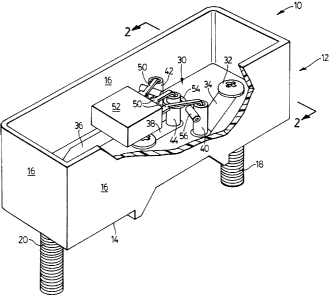
Referring now to Figures 1 to 4, a protector for use in a telecommunications
system to establish an electrical connection between two lines is shown and is
generally indicated to by reference numeral 10. In this particular example,
the
protector is in the form of a station protector to interconnect a
telecommunications
line in an external telecommunications cable to a service line extending to a
facility.
As can be seen, the station protector 10 includes an enclosed, generally
rectangular
housing 12 having a base 14, upright walls 16 about the periphery of the base
14 and
a top 17. The top 17 is removable to expose the interior of the housing 12. A
pair
of line terminals 18 and 20 depend from opposed ends of the base 14. One of
the
terminals 18 is to be connected to the telecommunications line while the other
terminal 20 is to be connected to the service line. A ground terminal 22 is
also
secured to the base 12 midway between the terminals 18 and 20 and extends to
one
side of the housing 12. The ground terminal 22 is to be connected to a ground
post
leading to electrical ground.
Surface mounted on the base 14 within the housing 12 is a printed circuit
board 30 (best seen in Figures 2 and 4). The printed circuit board is secured
to the
~I66~02
-5-
base 14 by a plurality of fasteners 32 passing through apertures 33 provided
in the
printed circuit board 20. Three copper traces 34, 36 and 38, each defining an
electrical path are on the printed circuit board. Copper trace 34 has one end
electrically connected to the terminal 18 by way of one of the fasteners 32
and
another end electrically connected to an upright metal tubular connector 40.
Similarly, copper trace 36 has one end electrically connected to the terminal
20 by
way of another of the fasteners 32 and another end electrically connected to
an
upright metal tubular connector 42. Copper trace 36 has one end electrically
connected to the ground terminal 22 by way of yet another fastener 32 and
another
end electrically connected to a third upright metal tubular connector 44
positioned
between connectors 40 and 42. The three connectors are accommodated by
apertures
46 provided in the printed circuit board 30 and are arranged in a row. The
connectors accommodate the pins 50 of an integrated circuit overload protector
52
such as that manufactured by Teccor of Texas under part number P152C.
A fail short 54 is associated with the tubular connectors 40, 42 and 44 and is
in the form of a conductor wound around the central tubular connector 44. The
two
free ends of the fail short 54 are covered by insulating material 56.
The operation of the station protector 10 will now be described. During
normal operating conditions, the overload detector 52 electrically connects
the
terminals 18 and 20 by establishing an electrical connection between copper
traces 34
and 36 while isolating the terminals from the ground terminal 22. When an
overload
condition occurs, the overload detector 52 connects the terminals 18 and 20 to
the
ground terminal 22 by establishing an electrical connection between copper
trace 38
and copper traces 34 and 36. If the overload condition passes, the overload
detector
52 resumes the electrical connection between the terminals 18 and 20 while
isolating
them from the ground terminal 22. If the overload condition persists or is
severe
such that the current through the station protector 10 exceeds the rating of
the
overload detector 52, the insulating material 56 covering the free ends of the
fail short
54 vaporizes establishing a permanent electrical connection between connectors
40,
42 and 44 and hence, between the terminals 18 and 20 and the ground terminal
22.
_ 21~6~Q
-6-
In this case, the station protector 10 must be replaced in order to
reestablish the
desired connection between the telecommunication and service lines.
During manufacture of the station protector 10, the connectors 40 to 44 are
inserted into the apertures 46 formed in the printed circuit board 30 and are
soldered
in place to connect them electrically to the copper traces 34 to 38. The fail
short 54
is then wound about the connector 44 and positioned to contact connectors 42
and 44.
The pins 50 of the overload protector 52 are then inserted into the connectors
and
soldered. With the printed circuit board 30 assembled in this manner, it can
be
placed in the housing 12 and secured to the base 14 by the fasteners 32,
allowing the
protector 10 to be assembled quickly and with ease. If desired, the overload
protector
52 can be soldered to the connectors 40 to 44 after the printed circuit board
30 has
been placed in the housing and secured to the base by the fasteners.
Referring now to Figures 5 to 7, another embodiment of a protector is shown
and is generally indicated to by reference numeral 110. In this embodiment
like
reference numerals will be used to indicate like components of the previous
embodiment with a "100" added for clarity. The protector 110 is of the plug-in
type
and is designed to plug into a terminal panel such as that disclosed in U.S.
Patent No.
5,044,962 issued on September 3, 1991 and assigned to the assignee of the
present
application, to establish an electrical connection between telecommunications
equipment in a facility and a service line. The plug-in protector 110 includes
a base
114 formed of insulating material. Depending from the base are a plurality of
terminal pins 115.
Surface mounted on the base 114 is a printed circuit board 130. The printed
circuit board is retained by uprights 131 on the base which pass through
apertures 133
provided in the printed circuit board. The printed circuit board 130 includes
three
copper traces 134, 136 and 138, each defining an electrical path. Copper trace
134
electrically connects two of the terminal pins to an upright metal tubular
connector
140. Similarly, copper trace 136 electrically connects two of the terminal
pins to an
upright metal tubular connector 142 while copper trace electrically connects a
ground
_7_
terminal pin to a third upright metal tubular connector 144 positioned between
connectors 140 and 142. The three connectors are received in apertures 146
provided
in the printed circuit board 130 and are arranged in a row. A gas tube
overload
protector 152 such as that manufactured by Joslyn of California under part
number
2026-35-C2 includes a pair of wire terminals which are accommodated by the
connectors 140 and 142. The third terminal of the overload detector 152 is in
the
form of a metal ring centrally positioned between other terminals and contacts
the
connector 144.
A fail short 154 is associated with the tubular connectors. The fail short is
in the form of a conductor wound around the central tubular connector 144. The
two
free ends of the fail short 154 contact a respective one of the other two
connectors
140 and 142 respectively. Unlike the previous embodiment, the ends of the fail
short
154 are electrically isolated from the connectors 140 and 142 by insulating
material
156 surrounding the connectors. As one of skill in the art will appreciate,
the
protector 110 is also easily assembled.
The present invention provides advantages in the design of the protectors
allows them to be manufactured quickly and easily as compared to prior art
designs.
This of course allows production to be increased while reducing labour costs.
Although the station protector has been shown to accommodate an integrated
circuit overload protector while plug-in protector has been shown to
accommodate a
gas tube overload detector, it should be realized that each protector can
accommodate
other types of overload protectors. It should also be appreciated that
variations and
modifications may be made to the present invention without departing from the
scope
thereof as defined by the appended claims.