Note: Descriptions are shown in the official language in which they were submitted.
2 ~ 56581
ADJUSTABLE WIDTH PANEL ASSEMBLY
BACKGROUND OF THE INVENTION
1. Field of the Invention
The invention relates to an adjustable-width panel assembly having first
and second panel members which include connecting means that provide lateral
movement of the panels relative to one another, whereby the cumulative width
of
the panel members is laterally adjustable to provide an efficient and
effective means
of construction for fences, privacy walls and similar structures incorporating
panels.
2. Description of the Prior Art
Fences and privacy walls constructed using numerous, interconnected
panels have been in use for many years. Typically, such structures utilize a
plurality
of panels fabricated from metals, alloys and thermoplastic materials. A number
of
means for connecting the panels to one another have been utilized, including
rivets,
screws, nails and similar fasteners.
Fences are typically constructed from wooden materials, with wooden
fence posts, typically 4 inches by 4 inches square in cross-section. A
stringer,
typically also 4 inches in width, is provided between posts near the upper and
lower
portions of the fence posts, as by the use of connectors such as nails. Panel
members, also typically of wooden construction, are nailed to the stringers on
one
either one side of the fence, the other side of the fence, or through various
alternating patterns.
In typical fence construction using wooden materials, the panel
members are mounted substantially coplanar with an outside surface of the
fence
post. This allows for continuous nailing of the wooden panel members to the
stringer, even over the fence post, as the panel members are attached along
numerous sections over the entire length of the fence. One advantage of such
construction is that precise placement of the posts is not necessary. Because
the
panel members are connected to the face of the stringers which is
substantially
coplanar with an outside surface of the fence post), exact spacing is
immaterial to
a successful installation or construction. However, wooden fences and other
types
of fences that require separate fasteners to fasten the panel members to the
fence
may have a number of disadvantages, as further described below.
- 1 -
>>66581
Other types of fence construction may involve the use of assemblies of
interconnected panel members. However, it has been found that attachment of
the
final panel member of each post-to-post section may require special attention,
such
as by cutting and trimming excess material, when the fence post was not
located
properly on, for example, 8 foot centers.
Further, use of separate fasteners may add additional, undesirable
expense to construction costs and may also contribute to failure of the
integrity of
the structure, due either to wear at the point of connection and/or
misapplication of
the fasteners by relatively unskilled workers. Additionally, use of such
fasteners may
not provide for expansion and/or contraction of the panel members due to
changes
in temperature or other factors. Moreover, use of such fasteners may be time
consuming and increase the time for construction, also allowing a tendency for
error,
which may reduce the quality of construction.
Other means have been utilized for interconnecting panel members that
eliminate the need for separate fasteners, including elaborate flange members
provided at opposite sides of the panels that matably fit with one another, as
well
as simple, arcuate portions which slidably engage one another to connect the
panels.
However, a number of such connection means may require that long, panels be
located lengthwise, end to end, taking care to maintain generally planar
alignment
between the members as the members are slidably moved to a side-by-side
relation.
Further, such means may not provide for expansion or provide for adjustability
of the
width of the panel assembly. Such slidable means may further increase the time
and
effort required for the construction, thereby increasing construction costs
and fatigue
of the workers.
Other connection means incorporating flange members may eliminate
some of the problems associated with slidable engagement and allow for
snappable
or rotatable connection. However, such connection means may not provide
adequate
tolerances at the point of connection for expansion of the panel members, may
require an undesirable degree of care in calculating the dimensions involved
and in
the placement of certain supporting structures that may be used in the
construction
of the fences, privacy walls and similar structures. Such panel connection
means
may further require additional labour such as for cutting or trimming of a
portion of
-2-
2~~65~7
the panel member to be connected to the supporting member where relatively
close
tolerances were not observed or where precise calculations were not done
and/or
when supporting structures, such as fence posts, were not carefully located.
Accordingly, prior to the development of the present invention, there
has been no adjustable-width panel assembly which: is simple and economical to
manufacture; is easily and quickly utilized; is effective to interconnect
successive
panel members without separate fasteners and provides lateral adjustability of
a
structure comprised of interconnected panel members. Therefore, the art has
sought
an adjustable-width panel assembly which: is simple and economical to
manufacture; is easily and quickly utilized; is effective to interconnect
successive
panel members without separate fasteners and provides lateral adjustability of
a
structure comprised of interconnected panel members.
SUMMARY OF THE INVENTION
A feature of the present invention is that, when successive panel
members are interconnected to span a distance such as a horizontal distance
between posts, the cumulative lateral movement of all panel members may
provide
a degree of lateral movement over a portion of the spanned distance sufficient
to
close a gap which may be present between the final panel and its supporting
post,
thus decreasing the close tolerances required and the need for the precise
calculations and care generally associated with placement of supporting posts.
In accordance with the invention, some of the foregoing advantages
have been achieved through the present adjustable-width panel assembly. The
panel
assembly of the present invention may include: at least one first panel
member,
having a desired length, a connecting portion, first and second side portions,
top and
bottom edges and inner and outer surfaces; at least one second panel member,
having a desired length, a connecting portion, first and second side portions,
top and
bottom edges and inner and outer surfaces and laterally adjustable connection
means
for connecting the connecting portion of the first panel member to the
connecting
portion of the second panel member whereby the first and second panel members
are
laterally movable relative to one another such that the width of the panel
assembly
is adjustable upon lateral movement of at least one panel member.
The present invention may further include a first matable means
-3-
21665~3~
disposed proximate the connecting portion of the first panel member and a
second
matable means disposed proximate the connecting portion of the second panel
member. Further, the first matable means may be either slidably or snappedly
engageable with the second matable means. Another feature of the present
invention is that the first matable means of the panel assembly may include a
generally hook-shaped member disposed at least partially along the length of
the first
panel member; the second matable means may include a generally box-shaped
member disposed at least partially along the length of the second panel member
and
at least a portion of the box-shaped member may be engageable with at least a
portion of the hook-shaped member.
An additional feature of the present invention is that the hook-shaped
member of the first panel member may include a body portion extending from the
inner surface of the first panel member generally transverse to the first
panel
member, the body portion having a length; the hook-shaped member may further
include an arm portion extending generally angularly from the body portion
generally
in the direction away from the first side portion of the first panel member
and
generally in the direction of the inner surface of the first panel member and
a channel
may be disposed between the body and the arm portions of the hook-shaped
member; the box-shaped member of the second panel member may include a first
body portion extending from the inner surface of the second panel member
generally
transverse to the second panel member, a second body portion disposed
proximate
the first body portion of the box-shaped member and extending generally in the
direction away from the second side portion of the first panel member, a leg
portion
disposed proximate the second body portion of the box-shaped member, the leg
portion extending generally in the direction of the inner surface of the
second panel
member and having a length and an arm portion disposed proximate the leg
portion
and extending generally angularly in the general direction of the first body
portion of
the box-shaped member, whereby the leg and arm portions of the box-shaped
member of the second panel member may be insertable into the channel of the
hook-
shaped member of the first panel member.
A further feature of the present invention is that the length of the body
portion of the hook-shaped member may be greater than the length of the leg
portion
-4-
2 i c~~58?
of the box-shaped member, whereby at least a portion of the box-shaped member
is loosely engageable with at least a portion of the hook-shaped member to
loosely
interconnect the first and second panel members such that each of the
interconnected panel members is laterally moveable relative one another. The
hook-
shaped member may include an arm portion, the box-shaped member may include
a leg portion and a first body portion and the arm portion of the hook-shaped
member
may extend between the leg portion of the box-shaped member and the first body
portion of the box-shaped member, thereby looseably connecting the first panel
member to the second panel member, allowing lateral movement of the first
panel
member relative the second panel member and generally preventing substantial
transverse and rotatable movement of the first panel member relative the
second
panel member.
In accordance with another aspect of the present invention, some of the
foregoing advantages have also been achieved through a fence of the present
invention. The fence may comprise: at least one first fence post; at least one
second fence post, spaced apart from the at least one first fence post to
provide a
post distance between the at least one first fence post and the at least one
second
fence post; at least one stringer and an adjustable width panel assembly
having a
width, comprising at least one first panel member, comprising a connecting
portion,
at least one second panel member comprising a connecting portion and laterally
adjustable connection means for connecting the connecting portion of the first
panel
member to the connecting portion of the second panel member, whereby the first
and second panel members are laterally movable relative to one another such
that the
width of the panel assembly is adjustable upon lateral movement of at least
one
panel member, the adjustable width panel assembly being attached to the at
least
one first fence post, the at least one second fence post and the at least one
stringer,
whereby the adjustable width panel assembly spans the post distance between
the
at least one first fence post and the at least one second fence post.
A feature of the present invention is that the at least one first panel
member may further comprise a length, first and second side portions, top and
bottom edges and inner and outer surfaces; the at least one second panel
member
may further comprise a length, first and second side portions, top and bottom
edges
-5-
Z1665~7
and inner and outer surfaces and the at least one second panel member may
further
comprise a length, first and second side portions, top and bottom edges and
inner
and outer surfaces. Another feature of the present invention is that the
adjustable
connection means may include: a first matable means disposed proximate the
connecting portion of the first panel member and a second matable means
disposed
proximate the connecting portion of the second panel member; the first matable
means may be either slidably or snappedly engageable with the second matable
means and may include a generally hook-shaped member disposed at least
partially
along the length of the first panel member; the second matable means may
include
a generally box-shaped member disposed at least partially along the length of
the
second panel member and at least a portion of the box-shaped member may be
engageable with at least a portion of the hook-shaped member.
The hook-shaped member of the first panel member may include a body
portion extending from the inner surface of the first panel member generally
transverse to the first panel member, the body portion having a length and the
hook-shaped member may further include an arm portion extending generally
angularly from the body portion generally in the direction away from the first
side
portion of the first panel member and generally in the direction of the inner
surface
of the first panel member and a channel may be disposed between the body and
the
arm portions of the hook-shaped member. Further, the box-shaped member of the
second panel member may include a first body portion extending from the inner
surface of the second panel member generally transverse to the second panel
member, a second body portion disposed proximate the first body portion of the
box-
shaped member and extending generally in the direction away from the second
side
portion of the first panel member, a leg portion disposed proximate the second
body
portion of the box-shaped member, the leg, portion extending generally in the
direction of the inner surface of the second panel member and having a length
and
an arm portion disposed proximate the leg portion and extending generally
angularly
in the general direction of the first body portion of the box-shaped member,
wherein
the leg and arm portions of the box-shaped member of the second panel member
are
insertable into the channel of the hook-shaped member of the first panel
member.
The present invention may further be directed to a method of
-6-
CA 02166587 1999-09-23
constructing a fence, comprising the steps of: providing a foundation;
providing
at least one first fence post proximate the foundation; providing at least one
second fence post proximate the foundation and spaced-apart a post-to-post
distance from the at least one first fence post; providing at least one first
stringer
having a length, two ends, a stringer connecting means for connecting the
stringer to the at least one first and second fence posts and a slot along its
length; disposing the at least one stringer between the at least one first and
second fence posts; connecting the at least one stringer to the at least one
first
and second fence posts; providing an adjustable-width panel assembly, having a
bottom edge, disposed between the at least one first and second fence posts,
the
panel assembly further having a bottom edge disposed within the stringer slot;
expanding the panel assembly to span the post-to-post distance and connecting
the panel assembly to the at least one first and second fence posts.
The method may further include the steps of: providing a snappable
projection proximate at least one end of the at least one first stringer;
providing
an aperture in the fence post adapted to receive at least one end of the
stringer;
inserting at least one end of the stringer into the aperture provided in the
fence
post and applying a compressive force to the stringer and the fence post to
snappedly engage the at least one end of the at least one first stringer
within the
fence post.
The invention in accordance with another aspect may provide an
adjustable-width panel assembly having a width and comprising at least one
first
panel member, at least one second panel member, a first laterally adjustable,
snappedly engageable, mating means proximate the connecting portion of the
first
panel member; and a second laterally adjustable, snappedly engageable, mating
means proximate the connecting portion of the second panel member. The at
least
one first panel member has a desired length, a connecting portion, first and
second side portions, top and bottom edges and inner and outer surfaces. The
at
least one second panel member has a desired length, a connecting portion,
first
and second side portions, top and bottom edges and inner and outer surfaces.
The first and second panel members may be snapped together and are laterally
movable relative to one another such that the width of the panel assembly is
CA 02166587 1999-09-23
adjustable upon lateral movement of at least one panel member.
The invention further provides a fence, comprising at least one first
fence post, at least one second fence post, spaced apart from the at least one
first fence post to provide a post distance between the at least one first
fence
post and the at least one second fence post, and at least one stringer. There
is
further provided an adjustable width panel assembly having a width, comprising
at least one first panel member, comprising a connecting portion, at least one
second panel member comprising a connection portion, a first laterally
adjustable,
snappedly engageable, mating means proximate the connecting portion of the
first
panel member and a second laterally adjustable, snappedly engageable, mating
means proximate the connecting portion of the second panel member. The first
and second panel members are laterally slidable relative to one another to
allow
the first and second mating means to be snapped together and are laterally
movable relative to one another such that the width of the panel assembly is
adjustable upon lateral movement of at least one panel member, the adjustable
width panel assembly being attached to the first fence post, the second fence
post and the at least one stringer, whereby the adjustable width panel
assembly
spans the post-distance between the at least one first fence post and the at
least
one second fence post.
The invention further provides a method of constructing a fence,
which comprises the steps of providing a foundation, providing at least one
first
fence post proximate the foundation, providing at least one second fence post
proximate the foundation and spaced a post-to-post distance from the at least
one
first fence post, and providing at least one first stringer having a length,
two
ends, a stringer connecting means for connecting the stringer to the at least
one
first and second fence posts and a slot along its length. The at least one
stringer
is disposed between the at least one first and second fence posts. There is
provided at least one first panel member, having a desired length, a
connecting
portion, first and second side portions, top and bottom edges and inner and
outer
surfaces, the at least one first panel member including a first laterally
adjustable,
snappedly engageable, mating means proximate the connecting portion of the at
least one first panel member. There is further provided at least one second
panel
- 7A -
CA 02166587 1999-09-23
member, having a desired length, a connecting portion, first and second side
portions, top and bottom edges and inner and outer surfaces, the at least one
first
panel member including a first laterally adjustable, snappedly engageable,
mating
means proximate the connecting portion of the at least one second panel
member.
The at least one first and second panel members are snappedly engaged together
to provide a panel assembly, and the panel assembly is then expanded to span
the
post-to-post distance. The panel assembly is then connected to the at least
one
first and second fence posts.
The adjustable-width panel assembly of the present invention, when
compared with previously proposed panel assemblies, has the advantages of
being simple and economical to manufacture, being easily and quickly utilized,
being effective to interconnect successive panel members without separate
fasteners and providing lateral adjustability of the resulting structure.
BRIEF DESCRIPTION OF THE DRAWINGS
In the drawings:
FIG. 1 is a perspective view of two successive panel members, in
accordance with the present invention, having matable means extending along
their entire lengths.
FIG. 2 is a perspective view of a panel member, in accordance with
the present invention, having a plurality of matable means spaced-apart along
its
length.
FIG. 3 is a cross-sectional view of a panel assembly of the two
s _
2 ~ c~65~7
successive, interconnected panel members of FIG. 1, taken along line 3 - 3 of
FIG.
1, in accordance with the present invention and showing an open gap for
lateral
expandability of the assembly.
FIG. 4 is a cross-sectional view similar to FIG. 3 of a panel assembly of
two successive, interconnected panel members, in accordance with the present
invention, wherein the gap shown in FIG. 3 has been closed to increase the
width
of the assembly.
FIG. 5 is a perspective view of a portion of a fence and two fence
posts, utilizing the adjustable-width panel assembly of the present invention,
showing
a closeable gap between a group of panel assemblies and a fence post.
FIG. 6 is a perspective view of an alternate embodiment of the present
invention showing a fence post rotated approximately 45 degrees and showing a
slot
for slidably attaching the panel assembly to the post without a separate
fastener.
FIG. 7 is a perspective view of a portion of a stringer and a portion of
a fence post, in accordance with the present invention, showing a stringer
connecting means for connecting the stringer to the fence post.
While the invention will be described in connection with the preferred
embodiment, it will be understood that it is not intended to limit the
invention to that
embodiment. On the contrary, it is intended to cover all alternatives,
modifications
and equivalents as may be included within the spirit and scope of the
invention as
defined by the appended claims.
DETAILED DESCRIPTION OF SPECIFIC EMBODIMENTS
In FIGS. 1 - 5, a panel assembly 600, in accordance with the present
invention is shown comprising at least two panel members 100, 200. In the
preferred embodiment, the panel members are preferably extruded from polyvinyl
chloride (PVC); however, the panel members may also be manufactured using any
suitable thermoplastic material, such as polypropylene, polyethylene, low
density
polyethylene (LDPE), vinyl acetate copolymers, vinyl chloride monomers (VCM),
or
acrylonitrile-butadiene-styrene (ABS), which may have the requisite
durability,
strength and flexibility characteristics which may be necessary for the
invention as
hereinafter described. Furthermore, panel members may also be manufactured
using
other materials and/or processes. For example, the panel members may be molded
_g-
2~ 6E58?
from a suitable thermoplastic material or may be extruded, or formed, by a die
from
metals or metallic alloys. The use of the term "panel assembly" throughout the
specification and the claims is intended to relate to any number of panel
members,
which may be interconnected and installed between fence posts or other
supporting
structures. Referring to FIGS. 3 and 4, it will be apparent that each panel
member
of the present panel assembly may be identical in structure, so that a
detailed
description of one may suffice for the others. Further, other supporting
structures
may be used; for example, a group of panel assemblies may be connected in a
continuous ring-shaped arrangement and fastened to a ring-shaped supporting
member for use as, for example, a composting or containing structure.
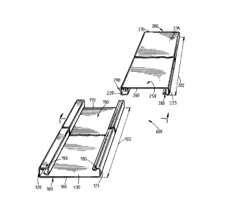
With reference to FIGS. 1 - 4, the adjustable-width panel assembly 600
of the present invention generally comprises: at least one first panel member
100,
having a desired length shown by arrows 102, connecting portions, or
connecting
means, 1 10, 1 1 1, first and second side portions 125, 120, respectively and
inner
and outer wall surfaces 130, 135, respectively; at least one second panel
member
200, having a desired length shown by arrows 202, connecting portions 210, 21
1
first and second side portions 225 and 220, respectively and inner and outer
surfaces 230 and 235, respectively; laterally adjustable connection means 300
for
connecting the first panel member 100 to the second panel member 200 and
disposed proximate the connecting portion 1 10, 1 1 1 of the first panel
member 100
and the connecting portions 210, 21 1 of the second panel member 200, whereby
the first and second panel members 100, 200, are laterally movable relative
one
another such that the width of the panel assembly 600 is adjustable upon
lateral
movement of at least one interconnected panel member 100, 200.
With respect to FIGS. 1 and 2, in a preferred embodiment, each panel
member 100, 200 may be of identical construction and be constructed of
thermoplastic material and may have a desired length 102, 202 providing a
generally
elongate body 150, 250. The body 150, 250 may be substantially planar.
Further,
the panel member 100, 200 may include a first side portion 125, 225 and a
second
side portion 120, 220 (which are defined as the lengthwise portions of the
panel
members 100, 200) disposed proximate connecting portions 1 10, 1 1 1 and 210,
21 1
(shown in FIGS. 3 and 4). Additionally, the body 150, 250 includes a top edge
160,
_g_
2'6581
260 and a bottom edge 170, 270. The preferred embodiment includes top and
bottom edges 160, 260 and 170, 270 respectively, lacking connecting portions.
Referring now to FIG. 3, the panel member 100, 200 includes first
connecting portion 1 1 1, 21 1 and second connecting portion 110, 210 provided
proximate first side portion 125, 225 and second side portion 120, 220,
respectively. The preferred embodiment includes connecting portions 1 10, 210
and
1 1 1, 21 1 formed integrally with the body 150, 250 and forming the first
side portion
125, 225 and the second side portion 120, 220. However, the connecting
portions
1 10, 210 and 1 1 1, 21 1 may also be attached to either inner surface 130,
230 or
outer surface 135, 235, as by the use of adhesives or other attachment means.
Further, connecting portions 1 10, 210 and 1 1 1, 21 1 may preferably form
first side
portion 125, 225 and second side portion 120, 220, respectively, or an
extension
portion (not shown) may extend beyond the connecting portions 1 10, 210 and 1
1 1,
21 1, where the connecting portions 1 10, 210 and 1 1 1, 21 1 are attached to
the
inner surface 130, 230 or the outer surface 135, 235 at a location inward of
the side
portions 125, 225, 120, 220.
Again, with reference to FIGS. 1 - 4, panel member 100, 200 may
comprise a first matable means 180, 280 adapted to be disposed proximate the
first
connecting portion 1 1 1, 21 1 and a second matable means 190, 290 adapted to
be
disposed proximate the second connecting portion 110, 210. The first matable
means 180, 280 includes a generally hook-shaped member 182, 282 disposed at
least partially along the length of the panel member 100, 200. In the
preferred
embodiment, the matable means 180, 280 extends substantially along the entire
length of the panel member 100, 200. However, as shown in FIG. 2, the matable
means 180, 280 and 190, 290 may also extend only partway along a portion of
the
length 102, 202 of panel member 100, 200 and may further comprise a plurality
of
matable means 180, 280 and 190, 290 spaced-apart along the length of panel
member 100, 200.
The hook-shaped member 182, 282 of the preferred embodiment
includes a body portion 183, 283, having a length L. The body portion 183, 283
extends from inner surface 130, 230 of the panel member 100, 200 generally
transverse and preferably s~.lbstantially perpendicular to the panel member
100, 200.
-10-
2 i 6~ 5~~7
The hook-shaped member 182, 282 further includes an arm portion 184, 284,
which
extends generally angularly from the body portion 183, 283 generally in the
direction
away from the first side portion 125, 225 of the panel member 100, 200 and
generally in the direction of the inner surface 130, 230 of the panel member
100,
200. The hook-shaped member 182, 282 further includes a channel 185, 285
disposed between the body portion 183, 283 and the arm portion 184, 284.
The second matable means 190, 290 includes a generally box-shaped
member 190, 290 disposed at least partially along the length of the panel
member
100, 200. However, as shown in FIG. 2, the matable means 190, 290 may also
extend only partway along a portion of the length of panel member 100, 200 and
may further comprise a plurality of matable means 190, 290 spaced-apart along
the
length of panel member 100, 200.
The box-shaped member 190, 290 of the preferred embodiment
includes a first body portion 191, 291 extending from the inner surface 130,
230 of
the panel member 100, 200 generally transverse to the panel member 100, 200.
The box-shaped member 190, 290 further includes a second body portion 192, 292
disposed in communication with the first body portion 191, 291 and extending
generally in the direction away from the second side portion 120, 220 of the
panel
member 100, 200. The box-shaped member 190, 290 further includes a leg portion
193, 293 disposed in communication with the second body portion 192, 292 of
the
box-shaped member 190, 290. The leg portion 193, 293 has a length L and
extends
generally in the direction of the inner surface 130, 230 of the panel member
100,
200. The box-shaped member 190, 290 further includes an arm portion 194, 294
disposed in communication with the leg portion 193, 293 and extending
generally
angularly in the general direction of the first body portion 192, 292.
Referring still to FIGS. 3 and 4, the interconnection of the first panel
member 100 and a second panel member 200 will be hereinafter described. First,
a first panel member 100 is provided, having a connecting means 1 1 1
comprised of
a hook-shaped member 182. Then, a second panel member 200, having a
connecting means 1 10 comprising a box-shaped member 290, is located in side-
by-
side relation to the first panel member 100 with its box-shaped member 290
overlying the hook-shaped member 182 of the first panel member 100, such that
the
- 11 -
Z~6~587
inner surface 230 of the second panel member 200 opposes the inner surface 130
of the first panel member 100. At least a portion of the box-shaped member 290
of
the second panel member 200 is snappedly engageable with at least a portion of
the
hook-shaped member 182 of the first panel member 100. The hook-shaped member
182 of the first panel member 100 defines a first matable means 180 while the
box-
shaped member 290 of the second panel member 200 defines a second matable
means 290, wherein the first matable means 180 is snappedly engageable with
the
second matable means 290. Opposing forces are applied to the first panel
member
100 and the second panel member 200, whereby at least a portion of the second
matable means 290 is loosely and snappedly engaged with at least a portion of
the
first matable means 180 to loosely interconnect the first panel member 100 and
the
second panel member 200 such that each of the interconnected panel members
100,
200 is laterally movable relative one another. Materials may be selected to
provide
sufficient rigidity and flexibility to allow the second matable means 290 to
be loosely
and snappedly engaged with the first matable means 180. It may be found that
some materials provide certain desired characteristics such as rigidity for
support of
the resulting structure while providing insufficient flexibility to yield for
snapping the
matable means 290 with the matable means 180. In practice, as opposing forces
are applied to the first panel member 100 and the second panel member 200, the
hook-shaped member 182 of the first panel member 100 and the box-shaped
member 290 of the second panel member 200 may yield in response to the
opposing
forces applied to the first and second panel members 100, 200, respectively.
Such
yielding may allow the hook-shaped member 182 of the first panel member 100 to
be locked in place within the box-shaped member 290 of the second panel member
200, thus providing engagement of the first panel member 100 with the second
panel member 200. Successive panel members may be similarly engaged with the
preceding panel members to provide a post-to-post panel assembly 650 (shown in
FIG. 5).
Alternatively, the first matable means 180 may be slidably engageable
with the second matable means 290. In such an embodiment, a first panel member
100 is provided having a first matable means 18 comprising a hook-shaped
member
182. Then, a second panel member 200 is provided, having a second matable
-12-
i 6~ ~~7
means comprising a box-shaped member 290. The first and second panel members
100 and 200 are then placed in end-to-end relation, being essentially coplanar
with
one another such that the inner surface 130 of the first panel member 100
opposes
the inner surface 230 of the second panel member 200 and whereby the first
matable means 180 is in essentially axial alignment with the second matable
means
290. The leg portion 293 and arm portion 294 of the box-shaped member 290 of
the second panel member 200 are inserted into the channel 185 of the hook-
shaped
member 182 of the first panel member 100. Then, the second panel member is
slidably moved into side-by-side relation with the first panel member 100. It
will be
understood that the arm portion 814 of the hook-shaped member 182 of the first
panel member 100 may also be inserted between the arm portion 294 and the
first
body portion 291 of the box-shaped member 290 of the second panel member 200,
whereby the first panel member 100 would then be slidably moved into side-by-
side
relation with the second panel member 200.
The dimensions of the box-shaped member 290 and the hook-shaped
member 182 are selected such that when the box-shaped member 290 is engaged
by the hook-shaped member 182, the first panel member 100 is loosely connected
to the second panel member 200, allowing lateral movement of the first panel
member 100 relative the second panel member 200 and generally preventing
substantial transverse and rotatable movement of the first panel member 100
relative
the second panel member 200. In the preferred embodiment, the loose engagement
is provided by a cap 98 between the leg portion 293 of the box-shaped member
290
and the body portion 183 of the hook-shaped member 182. When opposing forces
are applied to the first panel member 100 and the second panel member 200, a
portion of the leg portion 293 of the box-shaped member 290 contacts a portion
of
the body portion 183 of the hook-shaped member 182, thereby closing the gap
98.
Referring now to FIG. 4, a panel assembly 600 is shown in its expanded
position, whereby the gap 98 (shown in FIG. 3) between the leg portion 293 of
the
box-shaped member 290 and the body portion 183 of the hook-shaped member 182
is closed. A gap 99 may thereby be formed between the arm portion 294 of the
box-shaped member 290 and the arm portion 184 of the hook-shaped member 182.
The loose connection between the first panel member 100 and the second panel
- 13-
2 ~ ~65~7
member 200 allows for lateral adjustment, or expansion, of the panel assembly
600.
When successive panel members (not shown) are connected to the panel assembly
600 in a similar manner, the entire structure is expandable. The gap, such as
the
gap 98 shown in FIG. 3, provided where each panel member is joined to its
neighbouring panel member, provides a unit expansion distance. Where a number
of panel members are connected, the total expansion, or adjustment, distance
of the
resulting structure equals the sum of each unit expansion, or adjustment,
distance.
Referring now to FIG. 5, the construction of a fence 850 utilizing a
plurality of panel members 100 will be hereinafter described. First, at least
one first
fence post 700 is provided, which may be disposed proximate a foundation 851,
which may be earthen or comprised of concrete or some other composition known
in the art to be suitable for the support of a fence. In a preferred
embodiment, a
post hole is dug or otherwise created in the foundation material and a portion
of the
fence post 700 is deposited within the post hole. However, it should be
understood
that the fence may be free standing by utilizing any number of support means
well
known in the art. Then, at least one second fence post 701 is provided, spaced-
apart from the first fence post 700, which may be of similar construction to
the first
fence post 700 and similarly disposed proximate foundation 851. A stringer 800
is
provided, having a length sufficient to span a post distance 852 between first
fence
post 700 and the second fence post 701 and having sufficient length to be
connected to the fence posts 700, 701.
Referring now to FIG. 7, a preferred embodiment of a stringer
connecting means 801 is shown. Fence post 700, 701 may include an aperture 716
adapted to receive an end 804 of stringer 800. The stringer connecting means
801
may include a snappable projection 802 and an inner post surface 803 proximate
an
edge 807 provided at the periphery of aperture 716 of the fence post 700, 701.
An
end 804 of stringer 800 is inserted into fence post aperture 716 and a force
is
applied to the stringer 800 to force the stringer into the fence post 700, 701
to
snappedly engage the projection 802 with the edge 807 of a first fence post
700.
The second end 806 (shown in FIG. 5) of the stringer 800 is similarly engaged
with
a second fence post 701. In a preferred embodiment, the material composition
of
the stringer 800 may be selected to provide flexibility to bend the stringer
800 a
- 14-
~ 166531
sufficient amount to insert the second end 806 of stringer 800 into an
aperture 716
similarly provided in the second fence post 701. A force is similarly applied
to snap
the projection 802 of the second end 806 of stringer 800 into engagement with
the
inner post surface 803 provided at the periphery of aperture 716 of the second
fence
post 701. It should be noted that the snappable projection 802 may not provide
a
fixed distance between posts. Rather, the snappable projection 802 may simply
prevent the stringer 800 from slipping, out of engagement with the fence posts
700,
701. Moreover, the stringer 800 may be of any length sufficient to provide
support
along a substantial portion of both the collapsed width and the expanded width
of
the post-to-post assembly 650.
Referring now to FIGS. 5 and 7, a slot 805 may be provided along the
entire post distance, or post length 852 of stringer 800. A post-to-post
assembly
650 is provided in accordance with the present invention, which may be
comprised
of a plurality of panel assemblies 600. The bottom edges 170, 270 of the
plurality
of panel members 100, 200 of the plurality of panel assemblies 600 defines a
bottom edge 171 of the post-to-post assembly 650. The bottom edge 171 of the
post-to-post assembly 650 is then deposited in slidable engagement within slot
805.
A connecting portion 1 10, 210, 1 1 1, 21 1 of the post-to-post panel assembly
650
is attached to one of the fence posts 700, 701, such as fence post 701. In the
event that the post distance 852 is slightly greater than the collapsed width
of the
post-to-post assembly 650, the post-to-post assembly 650 is laterally expanded
so
that the not yet attached connecting portion 1 10, 210, 1 1 1, 21 1 of the
post-to-post
panel assembly 650 abuts the inner face 720 of the other fence post 700. The
not-
yet attached connecting portion 1 10, 210, 1 1 1, 21 1 of the post-to-post
panel
assembly 650 is then attached to the fence post 700. A second stringer 800 is
similarly provided proximate the top edge 160 of the post-to-post assembly
650,
whereby the top edge 160 of the post-to-post assembly 650 is deposited into
slidable engagement within slot 805 provided in the second stringer 800. The
ends
804, 806 of the second stringer 800 are similarly engaged by stringer
connecting
means 801 .
Preferably, the connecting portions 1 10, 210, 1 1 1, 21 1 of the post-to-
post panel assembly 650 are attached to the fence posts by way of conventional
-15-
~~ ~~5~7
fasteners, such as pop-rivets. However, other means of attaching the
connecting
portions 1 10, 210, 11 1, 21 1 to fence posts 700, 701 may be provided, as is
hereinafter described. By way of example, referring, now to FIG. 6, a slot 715
may
be provided along the length of fence post 700, 701, whereby a final panel
member
100, 200 may be slidably engaged by both a preceding panel member 100, 200 and
the slot 715 provided in fence post 700, 701. A cap 740 may then be provided
atop
fence post 700, 701 for cosmetic purposes and/or to provide further structural
integrity. Such an alternate means for attaching the connecting post-to-post
panel
assembly 650 to the fence posts 700, 701 may provide means for attachment when
the fence posts 700, 701 are rotated 45 degrees, which rotation may lessen the
flush engagement of the connecting portions 1 10, 210, 1 1 1, 21 1 provided
proximate the inner face 720 of the fence post 700, 701.
The operation of an embodiment of the present invention may be better
understood by way of the following description, which is to be understood as
being
presented for illustrative purposes only. For example, using a panel assembly
consisting of 19 panel members, the width of each panel member being 5.825
inches, constructed so that that gap is 0.120 inches, the collapsed width of
the
entire panel assembly equals 91.037 inches and the expanded width of the panel
assembly equals 93.097, thus providing a total expansion, or lateral
adjustment,
distance of 2.060 inches. Such expansion or lateral adjustment, distance may
allow
for installation of a fence using the panel assembly of the present invention
without
cutting of the panel members or the use of separate fasteners in a situation
where
the fence posts are not equally spaced on precise 8' centers.
By utilizing an adjustable-width panel assembly, one may provide
significant flexibility in the location of the supporting members to which the
panel
assembly may be connected. It should be noted that the dimensions heretofore
used
are illustrative only and the exact dimensions used in a particular embodiment
of an
adjustable-width panel assembly may vary according to the size of the panel
member
desired, the materials used and other factors.
It is to be understood that the invention is not limited to the exact
details of construction, operation, exact materials, or embodiments shown and
described, as obvious modifications and equivalents will be apparent to one
skilled
- 16-
2~ 6~5~1
in the art; for example, the body of the panel members may be configured
having
alternating, opposing U-shaped or V-shaped portions, or may be provided with
other
channels or ribs for strength or appearance. Also, successive panel members
may
be interconnected to span a distance such as a horizontal distance between
fence
posts or a vertical distance between fence stringers. Also, the top and/or
bottom
portions may include means for connecting the panel member to a supporting
structure such as a stringer where the panel member is installed vertically,
or a post
where the panel member is installed horizontally. Also, the laterally
adjustable means
for connecting the panel members may be used in combination with separate
fasteners once the panel assembly is in place to provide additional support.
Also, the
panels may be used in the construction of other structures such as roofs.
Also, any
number of panel members may be adjustable, with some panel members being non-
adjustable. Further, any suitable materials may be used and the surfaces of
the
present invention may include patterns such as to simulate, for example,
woodgrain.
Accordingly, the invention is therefore to be limited only by the scope of the
appended claims.
- 17-