Note: Descriptions are shown in the official language in which they were submitted.
2 1 ~`743
PATENT
WALL HEATER WITH IMPROVED HEAT EXCHANGER
Background of the Invention
Many different types of heating units are used in
residential and commercial buildings to heat the interior
of those buildings. One of these different types of
heating units is a forced air gas-fueled unit.
5 Frequently, these units are located centrally within the
building and duct work extends to registers positioned
throughout the building. These units include a burner
for heating air drawn into the unit and a fan or blower
for forcing the heated air through the duct work to
10 deliver the air to the registers. Usually, some type of
heat eYch~nger is used to heat the air so that the heated
air and combusted gases do not mix. Because the
combusted gases from the burner include high
concentrations of carbon monoxide which are hazardous to
15 humans, circulating the combusted gases throughout the
building is not desirable.
These centrally-located, forced-air, gas-fueled
heating units are highly efficient and work well for many
applications. However, in some applications the heaters
2 1 66~3
are not desirable. For example, in hotels and motels it
is desirable to permit the temperature in each room to be
individually controlled as each guest may be comfortable
when the air is within a different temperature range. In
5 order to achieve widely varying temperatures from room to
room, separate heater units are frequently employed.
Further, because the size of a hotel room or suite is
typically not as large as an entire house, the relatively
large centrally located furnaces used in houses are too
10 large for use in individual hotel rooms. Thus, smaller
heaters are desirable in hotel rooms. These smaller
heaters are compact, and are generally designed to be
positioned against an exterior wall of the room to
maximize the useable floor space in the room. As a
15 result, these smaller heaters are commonly referred to as
"wall heaters".
Another example where smaller heaters are
desirable is in additions to existing buildings. For
small additions, it is frequently uneconomical to re-
20 route and/or add onto the existing duct work. Further,sometimes even when the duct work could be re-routed
economically, the added load on the existing furnace
would be so great as to prevent it from effectively
heating the building. Thus, rather than re-route the
25 existing duct work or replace the existing furnace, it is
sometimes desirable to use a smaller second furnace in
additions to existing buildings.
Typically forced-air, gas-fueled wall heaters are
comprised of a cross-flow heat exchanger, a blower
30 positioned to force air from the room past pipes in the
heat exchanger, and a burner for heating air flowing
through the pipes. In addition, most wall heaters
include various control systems and sensors which
regulate the heater and shut down operation when the
35 sensors measure certain undesirable conditions. Prior
art heater units usually include only one blower which is
2 1 ~ 3
generally directed to force air over the central portion
of the heat exrh~nger. The heat exchangers in these
units may take one of several different configurations.
Typically, however, the exchangers include a mixed stream
5 flowpath and an Ul ; XP~ stream flowpath. As the name
suggests, the mixed stream flowpath is configured to
permit the air to circulate as it travels through the
exchanger so that the air emerges from the exchanger at a
uniform temperature. In contrast, the u~ixP~ stream
10 flowpath is configured to inhibit the air from mixing.
The burner is usually placed in series with the u~m;xPA
stream flowpath and the air from the room is usually
forced along the mixed stream flowpath. Thus, the
combusted gases travel through the unmixed stream
15 flowpath and the heated air travels through the mixed
stream flowpath and emerges at a uniform temperature.
Regardless of the actual configuration used, wall
furnaces are more desirable when they are more efficient,
less expensive and smaller. The ever increasing cost of
20 energy and the highly competitive nature of the HVAC
industry drive heater manufacturers to constantly seek to
improve the efficiencies of their heaters. Higher heater
efficiencies reduce fuel consumption thereby reducing the
consumer's heating costs and improving their salability.
25 As with most consumer goods, the less expensive they can
be manufactured without compromising effectiveness,
durability, and quality, the more desirable the product
is to the purchasing public. Therefore, the less
expensive a manufacturer can make a heater without
30 sacrificing quality and efficiency, the better. Finally,
because the space in hotel rooms and new construction is
at a premium, the smaller a heater unit can be made, the
more desirable it is.
21 6~7~3
-
Summary of the Invention
The heater of the present invention includes a
high efficiency cross-flow heat exchanger which is
designed in a compact size. Further, the heat exchanger
5 is uniquely designed to have an increased efficiency.
The heat exchanger is formed by one or more serpentine
tubes carrying the combusted gas upward through the
eYchAnger and the surrounding duct directs the air
downward across the tubes. The tubes are positioned
10 entirely within the duct so that the maximum heat
transfer surface area is utilized. Each heat exchanger
tube is comprised of horizontal runs connected by arcuate
return sections. Two blowers are used in the heater to
force air downward through the heat exchanger, downward
15 being the most desired. The blowers are positioned
directly over the return sections of the heat exchanger
tubes to maximize their thermal efficiency. Therefore,
high heat transfer coefficients are achieved throughout
the heat exchanger interior. In addition, the heat
20 exchanger tubes are nested to provide a compact size and
so that air flowing through the heat exchanger duct is
directed over different tubes as it passes through the
duct. This results in a more uniform temperature
distribution in the air flowing through the duct than
25 would otherwise be available.
Brief Descri~tion of the Drawinqs
Further objects and features of the present
invention are revealed in the following Detailed
Description of the Preferred Embodiment of the invention
30 and in the drawing figures wherein:
Figure 1 is an orthographic projection of the
exterior of the heater casing of the present invention;
Figure 2 is a front elevation view of the heater
of the present invention shown without the casing front;
21 66743
Figure 3 is a rear elevation view of the heater in
partial section: and
Figure 4 is a left side elevation view shown
without the left casing panel and shield to expose the
5 internal components.
Detailed DescriPtion of the Preferred Embodiment
The heater 10 of the preferred embodiment is of
the type configured for installation within a residential
or commercial building along an exterior wall of the
10 structure. This type of heater is c~, only referred to
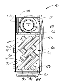
as a "wall heater". As best seen in Figure 2, the heater
10 of the preferred embodiment is generally comprised of
a casing 12 which houses a cross-flow heat exchanger 14,
a gas burner 16, two centrifugal blowers 18, 20 for
15 forcing the room air through the mixed stream flowpath of
the heat exchanger, a centrifugal inducer blower 22 for
drawing the combusted gases upward through the unmixed
stream flowpath of the heat exchanger, and a system
control panel 24 (see Figure 1) with an electronic
20 controller 26 which includes sensors for measuring the
ambient and system conditions and altering the system
operation in response to changes in the control panel
settings and the ambient and system conditions.
The casing 12 includes a base 30 which has an
25 integral back panel 32, as well as, left and right side
panels 34, 36, a top panel 38 and a front panel 40. Each
of these casing components is stamped from sheet metal
and assembled using sheet metal screw fasteners as is
well-known in the industry. As shown in Figure 1, the
30 front casing panel 40 includes a false upper grill 42 for
decoration and a working lower exhaust grill 44. The
integral back panel 32 includes three air intake openings
46, 48, 50 through which air is drawn from the ambient
surroundings within the room into the heater casing.
35 Once heated, the air is forced out of the casing through
2t6674~
the exhaust grill 44 at the lower side of the front
casing panel 40. A control panel access opening 52 is
provided in the top casing panel 38 and a door 54 is
pivotally connected to the top casing panel with a hinge
5 (not shown) to cover the control panel access opening
when the control panel 24 is not being adjusted.
The heat ~xch~nger 14 is housed within a duct 60
positioned inside the casing 12. The duct 60 is
comprised of left and right sheet metal shields 62, 64
10 which are located inside the left and right side panels
34, 36 of the case 12 and assembled with sheet metal
screw fasteners to the back panel 32 of the casing base
30. Bottom, top and front shields 66, 68, 70 are
positioned inside the respective casing panels and
15 fastened to the left and right shields 62, 64 to complete
the duct 60. The back panel 32 of the casing base 30
forms the rearward side of the duct 60. Two intake ports
(not shown) in the top shield 68 form the intake end of
the duct 60. The front shield 70 is fastened to the left
20 and right shields 62, 64 at a position spaced above the
base 30 so that an exhaust port 76 is formed between the
front shield and casing base behind the exhaust grill 44.
The exhaust port 76 forms the exhaust end of the duct.
The shields forming the duct are spaced from the casing
25 to form a dead air space. This space thermally insulates
the casing from the duct to prevent the casing from
becoming hot to the touch.
First, second and third serpentine exchanger tubes
80, 82, 84 are attached to the right shield 64 of the
30 duct 60. Holes (not shown) are punched in the right
shield 64 ad;acent the ends of the exchanger tubes 80,
82, 84 to provide the inlets to and the outlets from the
tubes. A bracket 86 is attached to the bottom shield
between the left and right shields 62, 64 to cradle the
35 serpentine exchanger tubes 80, 82, 84 along their lengths
~ t 6~43.
thereby holding them in position and reducing the
stresses in the tubes and adjoining components.
The first serpentine exchanger tube 80 includes
first, second, third and fourth runs 90, 92, 94, 96
5 separated by first, second and third return sections 98,
100, 102. The second and third serpentine exchanger
tubes 82, 84 have similar runs and return sections. As
best seen in Figure 4, the return sections of each heat
PYchanger tube are perpendicular with respect to each
10 other and obliquely oriented relative to the front shield
70 so that the first and third runs are both horizontally
and vertically offset from the second and forth runs.
Thus, each exchanger tube has a contorted Z-shape when
viewed from the side. The first and second exchanger
15 tubes 80, 82 are identically shaped and parallel one
another in the preferred embodiment. The third
serpentine exchanger tube 84 is designed with shorter
runs than the other tubes and the oblique orientations of
the return sections of the third tube are opposite those
20 of the other tubes so that the third tube compactly nests
within the envelope of the first and second exchanger
tubes. Thus formed, the heat exchanger 14 of the
preferred embodiment has a cross-flow configuration. In
other words, the predominant direction of air flow within
25 the exchanger tubes is generally perpendicular to the
direction of air flow through the duct in general.
Cross-flow results in higher heat transfer coefficients
than does parallel flow. Thus, the efficiency of the
heater is increased by using a cross-flow heat exchanger
30 rather than a parallel design.
The particular tube configuration described above
has several advantages. In some heaters, each exchanger
tube is configured to lie in a single plane. Thus, when
multiple tubes are used, air travelling through the duct
35 tends to contact different runs of the same tube rather
than different tubes. Because the different burners may
21 66743
not heat the air travelling through the different tubes
to the same temperature, the air travelling through the
duct may not be uniformly heated. As a result,
convective currents which reduce the heater performance
5 can develop within the heat exchanger. Each exchanger
tube in the heat exchanger of the preferred embodiment is
a contorted a Z-shape and the runs of each tube are
positioned at different forward and rearward locations
within the heat exchanger. Further, because the third
10 tube contorted Z-shape is opposite those of the first and
second tubes, the tubes are ordered in different
seql~e~c~ forward to rearward at different levels within
the exchanger. Thus, at one level the first tube may be
at the rearward-most position and at the next level
15 another tube may be in the rearward-most position. If
either of these tubes had an abnormal temperature
relative to the other tubes, the temperature effect on
the air passing over the abnormal temperature tube is
equalized by the temperature of the tube which is
20 encountered at the next level. Therefore, the thermal
gradients in the air traveling through the duct are
further reduced by the reverse-Z pattern.
The equalization of temperature gradients normal
to the direction of air travel through the heat exchanger
25 is further improved by the serpentine configuration of
each of the exchanger tubes. As hot air travels through
the tubes from the inlet adjacent the burner to the
outlet ad;acent the inducer, its temperature drops due to
heat transfer through the tube to the air passing through
30 the duct. Because the exchanger tubes run serpentine
through the heat exchanger, the hotter end of each run of
each tube is adjacent the colder end of the next run. As
a result, air passing over the colder end of a run does
not pick up as much heat as the air passing over the
35 hotter end. However, as the air passing over each colder
end continues on through the duct to the next run, it
2 1 66743
encounters a hotter end. Thus, the temperature
differential along the length of the runs is continuously
compensated for as the air passes between adjacent runs.
This continuous compensation minimizes thermal gradients
5 normal to the direction of air flow through the duct.
Although prior art centrally-located, forced-air,
gas-fueled heating units used serpentine exchanger tubes,
the serpentine configuration in those units was generally
planar rather than a contorted Z-shape. As flow
10 restrictions in tubes increase with tighter radii of
curvature and the distance between runs in planar tubes
may only be decreased by reducing the radius of curvature
of the return sections, the prior art planar serpentine
tubes had a practical minimum height limit which could
15 not be reduced without causing significant flow
restrictions. Because the practical height of wall
heaters is limited, the use of several runs in any one
tube was prohibited as a result of the minimum height
limit inherent with the prior art planar serpentine
20 eYc~Anger tubes. However, the contorted Z-shape of the
tubes of the present invention enables shorter exchangers
to be made with more runs thereby permitting the
effective use of serpentine tube heat exchangers in wall
heaters. In addition, the Z-shape and reverse-Z enable
25 the tubes to be nested thereby further optimizing the use
of space and increasing the heater performance.
The gas burner 16 is positioned adjacent the
inlets of the serpentine exchanger tubes 80, 82, 84.
Although the configuration of the burner differs slightly
30 depending upon whether liquified petroleum (LP) gas,
natural gas or another fuel source is intended to be
burned, the burner 16 is generally comprised of a
manifold 110 having a flow regulator 112 positioned along
its length. Holes (not shown) are machined into the side
35 of the manifold 110 and orifices (not shown) are threaded
into the manifold holes. The orifices are generally
2 1 66743
aligned with the exchanger tube inlets. As is common in
the industry, flame holder assemblies (not shown) having
carburetors along their lengths are positioned adjacent
the orifices to mix air drawn in through the inlet port
5 114 with the gas which is blown from the orifices. The
carburetors are adjustable so that the amount of air
which is mixed with the gas may be altered to produce an
optimally burning mixture. The flame holders are
configured to direct the flame from the burner into the
10 inlets of the exchanger tubes 80, 82, 84. An electronic
spark ignitor (not shown) is positioned within the burner
16 adjacent the flame holders to ignite the gas-and-air
mixture and light the burner. Thus, the need for a pilot
light or manual ignition is eliminated. The burner also
15 includes a flame sensor 126 and a flame roll-out limit
switch 128 which are connected to the system controller
26 to shut down the heater in the event the burner fails
to light or the flame rolls out of the flame holder as
will be explained in greater detail below.
Mounted adjacent the outlets of the exchanger
tubes 80, 82, 84 is the inducer blower 22 which is
generally comprised of a low profile squirrel cage
impeller 130 and a fan motor 132. The inducer includes
an inlet port (not shown) and an exhaust port 134 so that
25 the combusted gases from the burner 16 are drawn through
the ~YchAnger tubes 80, 82, 84 through the inducer inlet
port and forced out the exhaust port 134. A vent
assembly as is common in the industry is connected to the
exhaust port to direct the potentially harmful combusted
30 gases out of the heater and to the exterior of the
building.
The centrifugal blowers 18, 20 are mounted
adjacent the inlet ports in the top shield 68. The
blowers are driven by an electric motor 140 mounted on
35 the top shield which forms part of the duct. The three
air intake openings 46, 48, 50 provided in the back panel
21 66743
-
32 behind the centrifugal blowers 18, 20 permit air to be
drawn into the heater and forced through the intake ports
of the heat exch~nger duct 60. An air filter (not shown)
may be mounted between the intake openings 46, 48, 50 and
S the centrifugal blowers 18, 20 to filter dust and other
particulate matter from the air being drawn into the
heater 10. In the preferred embodiment, a temperature
limit switch 148 is mounted between the centrifugal
blowers 18, 20 in the top shield 68 for preventing the
10 heater from excee~ng an upper temperature limit as will
be explained in greater detail below. The centrifugal
blowers 18, 20 are positioned above the return sections
of the exchanger tubes 80, 82, 84. Thus, the blowers
force a relatively large mass flow rate of air over the
15 return sections in a direction opposite the air flowing
through the return sections. Counterflow heat transfer
coefficients are higher than parallel flow coefficients.
Thus, not only is the entire length of each exchanger
tube positioned within the heat exchanger duct so that
20 maximum heat transfer area is achieved, but the heat
transfer coefficients at each location in the heat
exchanger are maximized by directing larger amounts of
air over the exchanger tube return sections. Therefore,
a highly efficient heat exchanger is achieved by the
25 configuration of the present invention.
The system control panel 24 is mounted
horizontally in the casing immediately below the control
access panel 48. The control panel 24 includes an on-off
switch 160, a temperature adjustment knob 162 and a light
30 emitting diode (LED) fault indicator 164. The on-off
switch 160, temperature adjustment knob 162 and fault
indicator 164 are electrically connected to the
electronic controller 26 mounted immediately below the
system control panel 24. The electronic controller 26
35 includes a thermostat for measuring the room temperature
and determining when the heater should be turned on or
21 66~43
off to achieve the temperature setting of the temperature
adjustment knob 162. Also included in the controller 26
is a pressure sensor 166 for measuring the pressure drop
across the inducer blower 22. If the pressure drop is
5 below a predetermined limit, the controller 26 is
signalled as this condition is an indication that the
combusted gases are not being properly vented. The light
emitting diode (LED) 164 located on the control panel 24
is energized when the controller 26 is signalled that
10 there is insufficient pressure drop to alert the user of
the potentially hazardous condition. The fuel to the
burners and the power to the blowers is also interrupted
when this condition is sensed to prevent buildup of the
combusted gases within the heater and building interiors.
A flame sensor circuit is incorporated in the
system to sense whether a flame is present in the burner.
The previously mentioned flame sensor 126 is connected to
the electronic controller 26. If a flame is not present,
the sensor 126 sends a signal to the electronic
20 controller 26 which in turn shuts down the heater and
energizes the LED fault indicator 164 as previously
described.
Also included in the control circuit is the
temperature limit switch 148 (see Figure 2) which assures
25 that the heat exchanger does not become too hot. If the
temperature within the heat exchanger exceeds a
predetermined limit, the controller 26 is signaled to
shut down the heater operation and the LED fault
indicator 164 is energized. Likewise, the flame roll-out
30 switch 128 is employed to assure that flame roll-out does
not occur in the burner. If the flame should roll out of
the burner, the controller 26 is signaled to shut down
the heater and the fault indicator 164 is energized. The
controller 26 is also equipped with a logic circuit which
35 determines which type of fault has occurred be it failed
ignition, over temperature, flame roll out or an
2 1 6~743
insufficient pressure drop through the heat exchanger and
sends a different sequence to the fault indicator 164 so
that the type of fault can be determined easily by the
user.
In addition to providing heat, an optional air
conditioning coil (see Figures 3 and 4) may be added to
the unit between the air filter and centrifugal blowers
18, 20 to cool the air rather than heat it.
During system start-up, the thermostat circuit
10 closes thereby energizing the inducer blower circuit for
about fifteen seconds to pre-purge any gas and close the
pressure switch. Once the gas is purged, the hot surface
ignitor is energized and after an approximately seventeen
~econ~ warm-up, the gas valve circuit is energized to
15 open the gas valve and ignite the burners. After the
burners are lit for about thirty seconds, the circulating
air blower comes on, delivering warm air to the room. If
ignition does not occur, the ignition sequence is
repeated again up to two additional times. If the system
20 does not ignite, the inducer blower, ignitor, gas valve
and air blower circuits are de-energized and the LED
fault indicator is energized.
After the furnace operates and satisfies the pre-
set temperature of the thermostat, the gas valve closes
25 and the circulating air blower continues to run for about
two minutes and then shuts off. The inducer blower runs
for about five additional seconds after the air blowers
stop to assure that the heater is sufficiently purged of
potentially hazardous combustion by-products.
In alternative embodiments, fewer or more
exchanger tubes may be employed in the heat exchanger.
Likewise, fewer or more orifices and flame holders are
used with the one and two tube heat exchanger tube
systems. In addition, different exchanger tube
35 configurations may be used without departing from the
scope of this invention.
2 1 667~3
14
Thus configured, the heater of the present
invention provides a compact unit having high thermal
efficiency. Thermal gradients across the air output from
the heater are minimized thereby eliminating cold spots
5 and improving heater efficiency. Further, because the
air is exhausted through the grill near the bottom of the
heater, it provides additional comfort to the users as
convection permits the heated air to rise throughout the
room thereby promoting circulation.
While the present invention has been described by
reference to a specific embodiment, it should be
understood that modifications and variations of the
invention may be constructed without departing from the
scope of the invention which is limited only by the scope
15 defined in the following claims.