Note: Descriptions are shown in the official language in which they were submitted.
2~6~9~1
IMPROVED COAL PULVERIZER CLASSIFIER
CONE AND CONTROL SYSTEM
Field of the Invention
The invention relates in general to coal pulverizers,
and more particularly to improvements in the coal feed and
classifier cone structure associated with such pulverizers.
Backqround of the Invention
Coal-fired combustion systems such as those used in
large utility applications require finely-ground coal
particles or "fines" for efficient operation. In general,
it is desirable to use only very-finely pulverized coal in
such systems in order to keep NOX emissions and oversized
loss-on-ignition (LOI) unburned coal particles from
contaminating the marketable ash byproduct of the
combustion chamber. It is accordingly important to
maintain close control over the fineness of the pulverized
coal fed into the combustion system.
Bowl mill-type pulverizers, such as the type disclosed
in U. S . Patent No. 4, 687, 145, are commonly used to grind
the coal and classify the resulting fines. A vertical
feedpipe drops raw coal from several feet above the
pulverizer to the center of the pulverizer for grinding.
2
~16694~
An annular and upwardly-directed flow of air through a
ring-shaped "throat" blows the ground coal particles up and
around the pulverizer to a classifier system and combustion
chute feeding the combustion chamber. The classifier
system removes oversized particles of coal from the flow of
air and coal fines, returning them to the pulverizer for
regrinding.
A known system for classifying these upwardly
traveling fines consists of an inverted classifier cone
mounted above the pulverizer and concentric with the
feedpipe that delivers raw coal to the center of the
pulverizer. The lower, smaller outlet end of the
classifier cone essentially surrounds the outlet end of the
feedpipe, while the larger, upper inlet or mouth of the
cone surrounds the combustion delivery chute.
A stationary ring of classifier vanes is mounted at
the mouth of the cone to receive the annular, upward flow
of pulverized coal/air from the pulverizer and redirect it
into the classifier cone in a centrifugal flow. As the
coal fines and air swirl around in the classifier cone, the
heavier particles gravitate to the sides and settle out at
the bottom of the cone, while the lighter, more finely
ground fines are swirled up and into the entrance of the
combustion delivery chute.
As the heavier particles of coal collect at the bottom
of the classifier cone, they are typically contained by a
flapper valve assembly at the bottom of the cone,
2
CA 02166941 1999-07-26
comprising a series of vertically hanging plates blocking
the openings of one or more outlet chutes. The plates are
relatively heavy, and are forced open only intermittently
by the weight of the accumulated c-oal at the bottom of the
classifier cone. These fine "rejects" then fall into the
bowl mill pulverizes along with incoming raw coal from the
feedpipe for regrinding.
There are a number of disadvantages inherent in prior
art systems such as those described above.
The prior art positioning of the feedpipe and
classifier cone outlets well above the pulverizes often
results in fine rejects being blown back up through or
around the classifier cone when the flapper assembly opens
for a discharge. This is primarily due to the position of
the outlets relative to the annular flow of coal fines/air
from the pulverizes throat.
Moreover, the flapper assembly and other prior art
intermittent cone discharge systems such as "hula skirt"
assemblies (circular arrangements of overlapping metal
leaves) can become stuck in an open position, adding to the
problem of fine reject backflow into the combustion
delivery chute and further defeating the function of the
classifier cone.
In U.S. Patent No. 5,386,619 issued February 7, 1995 to Wark, I disclosed an
improvement upon the prior art coal pulverizes systems described above wherein
the
various air and coal flow paths throughout the pulverizes
3
2166~~1
are optimized to prevent them from interfering with one
another. In one form of that invention the feedpipe and
classifier cone are extended to eliminate the adverse
effects of the annular fine-lifting air flow from the
pulverizer throat on the function of the classifier cone,
to improve the intrinsic functioning of the classifier
cone, and to eliminate the need for complex and unreliable
intermittent discharge structure in the classifier cone.
This is generally achieved by extending the feedpipe
and classifier cone such that the drop-points for raw coal
from the feedpipe and for reject fines from the cone are
within, rather than above, the pulverizer. These
extensions significantly reduce the tendency of the
annular, fine-lifting flow around the outside of the
pulverizer to deviate and work back up against the flow of
raw coal and fine rejects into the pulverizer.
The reject fines spiraling down the cone around the
feedpipe are further drawn into the pulverizer by an
improved pressure flow effect from the extended feedpipe in
a manner which prevents diversion of the fines back up into
or around the classifier cone.
In a particular embodiment of my previous invention,
the flapper valve or other intermittent discharge structure
is removed from the classifier cone outlet, and replaced
with a continuous flow feedpipe extension extending well
below the original classifier cone outlet to a point
proximate the grinding surface of the pulverizer. The
4
- ~~.~~94~
classifier cone is extended in similar fashion with an
extension concentric with the feedpipe and extending into
the pulverizer to a point proximate the feedpipe extension
outlet. In a preferred form the classifier cone extension
extends into the pulverizer slightly farther than the
feedpipe extension, with its outlet slightly below that of
the feedpipe extension, such that the raw coal flow through
the feedpipe creates a desirable pressure flow effect
drawing the reject fines from the cone into the pulverizer.
The continuous-flow feedpipe and classifier cone
extensions, when properly adjusted relative to the
pulverizer and its annular fine-lifting airflow, provide a
steady flow equilibrium not attainable with the
intermittent discharge structure which they replace.
Occasionally, however, the dimensions and geometry of
the feedpipe and the classifier cone are such relative to
one another that the feedpipe extension interferes with the
flow of coal fines through the classifier cone extension.
For example, the feedpipe may be oversize in diameter to
accommodate a required feed rate, with the result that the
feedpipe extension fits too closely within the classifier
cone extension for proper flow between the feedpipe
extension and the cone extension.
Summary of the Invention
The problem described above is solved with the present
invention by leaving the feedpipe its original length, or
5
by providing a shortened feedpipe extension, such that the
feedpipe outlet terminates above the throat of the
classifier cone extension. In a preferred form the
feedpipe outlet terminates within the cone extension above
the throat of the extension.
In a further form of the present invention, an
adjustable clearance device is retained on the lower end of
the feedpipe or the feedpipe extension adjacent the throat
of the classifier cone extension. The clearance device is
vertically adjustable on the feedpipe to regulate the size
of the annular flow path around the lower end of the
feedpipe relative to the throat of the classifier cone
extension as needed, without interfering with the
classifier cone extension.
These and other features and advantages of the
invention will become apparent upon a further reading of
the specification.
Brief Description of the Drawinqs
FIGURE 1 is a side section view of a prior art
classifier system in a bowl mill pulverizer;
FIGURE 2 is a side section view of a classifier system
according to my previously disclosed invention, also in a
bowl mill pulverizer;
FIGURE 3 is a side section view of a classifier system
according to the present invention, also in a bowl mill
pulverizer.
6
216G9~1
Detailed Description of the Drawings
Referring first to Figure 1, a known bowl mill-type
pulverizer 10 is shown in partial side section, comprising
a pair of grinding rollers 12 mating with the grinding
surfaces of the grinding ring 14. Grinding ring 14 is
driven by a standard drive system shown schematically at 16
and a connecting yoke 18, rotating ring 14 relative to
rollers 12. A feedpipe 20 extends from a suitable storage
mechanism to deliver raw coal by gravity feed to the center
of the bowl mill pulverizer 10. The incoming coal is
diverted by a deflector 22 radially outward to the grinding
rollers 12 and grinding ring 14, where it is crushed or
ground into a relatively fine particulate form.
The base of pulverizer 10 includes a surrounding,
ring-shaped pulverizer throat region 26 fed with air from
an outside source via plenum 28 to deliver an annular flow
of air up and around the periphery of pulverizer 10.
Pulverizer throat region 26 may be provided with a throat
(not shown) having a number of fixed or adjustable vanes or
deflectors which determine the velocity of air flow. A
particularly useful throat and vane/deflector structure is
disclosed, for example, in my U.S. Patent No. 5,186,404.
The upward, annular air flow through pulverizer throat
26 lifts the ground coal particles from ring 14 up and
around pulverizer 10 in region 11 to the top of the
pulverizer. The velocity of air through throat 26 performs
an initial classifying function by lifting and carrying
7
.~I6~94~
only coal particles below a certain size.
The upper end of the pulverizer housing is provided
with a further classifying system comprising a classifier
ring 30 having a horizontal inlet 31 about its periphery,
an inverted classifier cone 32, and a combustion delivery
chute 34. Classifier ring 30, classifier cone 32 and
combustion delivery chute 34 are mounted in concentric
fashion about feedpipe 20. The upper end of classifier
cone 32 surrounds the combustion delivery chute 34, with
classifier ring 30 filling the gap therebetween. The
annular lifting flow of air and coal fines from pulverizer
throat 26 accordingly enters cone 32 and combustion
delivery chute 34 through classifier ring 30.
Classifier ring 30 includes a number of fixed
vanes (not shown) which impart a centrifugal component to
the air and coal fine flow entering the cone from region 11
of the pulverizer. As the coal fines and air swirl around
in the classifier cone, the heavier particles gravitate to
the sides and settle out at the bottom of the cone, while
the lighter, more finely ground fines are swirled up and
into the combustion delivery chute to the combustion
chamber.
As the heavier particles of coal drop to the bottom of
the classifier cone, they are contained by a "flapper" or
similar intermittent discharge assembly 36 at the bottom of
the cone, which releases these collected fine rejects to
the pulverizer for regrinding. Figure 1 shows a common
8
2I6fi94~
type of flapper assembly comprising a series of vertically
hanging plates blocking the openings of one or more outlet
chutes in the bottom of cone 32. The plates are hingedly
mounted, and are relatively heavy, such that they are
forced open only intermittently by the weight of the
accumulated reject fines at the bottom of the classifier
cone.
Other types of intermittent discharge structure are
known in the art, but the form of the intermittent
discharge structure is not important to the present
invention.
Still referring to Figure 1, it can be seen that the
height or drop-point of the outlets of the feedpipe 20 and
classifier cone 32 are spaced well above the grinding
apparatus 12, 14 of pulverizer 10. I have found through
experience that this positioning subjects the raw coal flow
from the feedpipe and the intermittent reject discharge
from the classifier cone to the effects of the annular air
flow from the pulverizer throat 26. Turbulence and
deviation of the annular air flow around and above the
pulverizer grinding structure 12, 14 is aggravated by the
air flow disturbances created in the region of the feedpipe
and classifier cone outlets as raw coal and reject fines
are continuously or intermittently dumped onto grinding
ring 14. Accordingly, not only does the position of the
prior art feedpipe and classifier cone outlets inherently
expose the downward coal flow to air flow disturbances, but
9
CA 02166941 1999-07-26
it further compounds the magnitude and effect of those
disturbances.
The result is oversized reject fines and small pieces
of the raw feed coal being blown back up through or around
the classifier cone, thereby thwarting its classifying
function. These oversized particles can end up being
delivered to the combustion chamber through the combustion
delivery chute 34, reducing the effectiveness of the
combustion process, wasting coal and contaminating the
marketable ash byproduct with Z,OI lumps.
The flapper or other intermittent discharge structure
36 is also subject to mechanical jamming or malfunction.
Moreover, the intermittent nature of the fine reject
discharge further increases the disruptive effects of the
fine rejects on the overall flow equilibrium of the
pulverizer.
Referring now to Figure 2, a number of structural
modifications to prior art pulverizer classifying systems
are shown according to my U.S. Patent No. 5,386,619
issued February 7, 1995 to Wark. In Figure 2 the general
pulverizer structure is the same as that shown in Figure 1,
and is referred to by the same reference numerals.
However, flapper assembly structure 36, 38 has been
replaced by a cylindrical feedpipe extension 136 and a
sectional classifier cone extension 140. This modification
of classifier cone 32 and feedpipe 20, and the
corresponding elimination of the intermittent discharge
216694.
flapper structure 36, 38 greatly improves the air and coal
flow throughout the pulverizer and classifier system and
the control over the fineness of coal ultimately delivered
to the combustion chamber.
As shown in Figure 2, feedpipe extension 136 is a
cylindrical extension bolted or otherwise securely fastened
to the end of feedpipe 20 at 138, for example by welding.
Of course, other suitable ways of connecting the feedpipe
extension to the feedpipe will be apparent to those skilled
in the art. In the illustrated embodiment, the feedpipe
extension extends approximately five to six feet below the
original feedpipe outlet, to a point within grinding
rollers 12 and no more than two to three feet above
deflector 22 and grinding ring surfaces 14. The feedpipe
extension 136 accordingly extends well below the original
outlet or drop-point of feedpipe 20 and classifier cone 32
located above the pulverizer~structure, to a point within
the confines of the grinding structure and adjacent the
grinding surface.
Sectional classifier cone extension 140 is similarly
securely fastened to classifier cone 32 at 146, in the
illustrated embodiment by suitable bolt structure. Cone
extension 140 includes an upper cone-shaped portion 142
contiguous with classifier cone 32, and a cylindrical
tailing portion 144 concentric with and parallel to
feedpipe extension 136. The outlet of classifier cone
extension 140 adjacent the grinding structure 12, 14 is
11
_ ~1669~.~
located slightly below the outlet of feedpipe extension
136, creating a desirable pressure flow effect described in
more detail below.
Although in the illustrated embodiment the feedpipe
and classifier cone extensions 136, 140 are shown as
retrofit, bolt-on extensions of the original classifier
structure, it will be apparent to those skilled in the art
that the feedpipe 20 and/or classifier cone 32 could be
originally manufactured with the extended portions 136, 140
to be located relative to the pulverizes structure as shown
in Figure 2. It is expected, however, that the primary
market for extensions 136, 140 will be as retrofit devices
to existing prior art structures.
The extension of the classifier cone in the manner
described above produces a number of desirable results with
respect to the flow of coal and air throughout the
pulverizes and classifier system.
Classifier cone extension 140 isolates the fine reject
discharge from the annular airflow out of the pulverizes
throat 26 in region 11, and simultaneously prevents the
discharge from aggravating any disturbances in that annular
airflow. The effective lengthening of the angled
classifier cone 32 by sectional cone portion 142 allows
more time for the coal fines to be swirled around and
classified in cone 32, providing more control over the size
of the fines ultimately fed to the combustion chamber via
delivery chute 34. Additionally, the reject fines which
12
2166941
require regrinding in the pulverizer spiral down around the
feedpipe and are further drawn by the feedpipe flow onto
the pulverizer in a manner which decreases the likelihood
of reject fines being blown back up into or around the
classifier cone. The location of the classifier cone
extension outlet below the mouth of the feedpipe enhances
this pressure flow or draw, created by the raw coal flowing
downward between the parallel walls of feedpipe extension
136 and cone extension 140.
Of course, the elimination of the unreliable
intermittent discharge structure 36, 38 reduces the chance
of clogging or jamming at the cone outlet. The continuous-
flowing nature of the cone extension 140 further helps
maintain a smooth flow equilibrium between the downwardly-
flowing reject fines and the annular fine-lifting flow from
throat 26; intermittent discharge structure tends to upset
this equilibrium.
An additional feature of the present invention is an
adjustable classifier venturi 148 mounted on the upper end
of feedpipe 20 adjacent the inlet of combustion delivery
chute 34. Classifier venturi 148 is vertically adjustable
on feedpipe 20 toward and away from the mouth of delivery
chute 34 via any suitable mechanical or motorized control
means (not shown).
Classifier venturi 148 defines two sets of venturi
surfaces: lower venturi surfaces 150 and upper surfaces
152. By raising and lowering the classified venturi
13
21669~~
relative to combustion delivery chute 34, the velocity and
angle of the coal fines exiting cone 32 can be adjusted
with a great degree of control. When venturi 148 is
raised, thereby reducing the size of the combustion chute
inlet, the escape velocity of coal fines and air increases
in accordance with well-known principles. At the same
time, the opposing angle upper and lower venturi surfaces
150, 152 adjust the exit angle of the air and coal fines,
reducing the exit angle to a progressively more vertical
direction parallel to delivery chute 34 at feedpipe 20.
Conversely, as classifier venturi 148 is lowered away
from the inlet of delivery chute 34, the exit velocity is
decreased and the exit angle correspondingly increases in
somewhat arcuate fashion, becoming progressively more
angled relative to the delivery chute 34 and feedpipe 20.
By way of further explanation, when classifier venturi
148 is in the lower position shown in solid lines in Figure
3, the exit angle of the lighter fines swirling in the
upper part of cone 32 is essentially parallel to upper
venturi surfaces 152 and accordingly at a relatively sharp
angle relative to chute 34. When classifier venturi 148 is
in the raised position shown in dotted lines in Figure 3,
with the upper leading edges of lower surfaces 150
essentially even with the plane of the inlet of delivery
chute 34, the exit angle is essentially vertical and
parallel to chute 34.
The lower venturi surfaces 150 of venturi 148 further
14
~1669~1
act as angled deflectors, contacting the coal as it exits
the cone near chute 34 and significantly slowing down
larger particles of coal entrained in the exit flow. This
reduces their velocity and causes them to drop back into
the classifier cone for regrinding.
The dual-surfaced venturi 148 creates a complementary
relationship between the exit angle and exit velocity of
the coal flow leaving cone 32 via chute 34. As venturi 148
is raised to increase exit flow velocity, the simultaneous
change in the exit angle toward the vertical results in a
greater deflection of the centrifugally-swirling coal in
the upper portion of cone 32 by surfaces 150. Accordingly,
while undesirable larger coal particles may tend to be
prematurely classified with the exit flow due to the higher
escape velocity, they are also more likely to strike and be
decelerated by lower surfaces 150 during the transition
from radially swirling classification flow essentially
perpendicular to delivery chute 34 to a nearly vertical
exit flow.
The increase in exit flow velocity through delivery
chute 34 is largely dictated by the flow rate needed by the
combustion chamber.
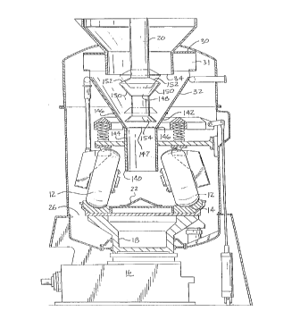
An adjustable clearance cone 154 is also provided on
the lower end of feedpipe 20 adjacent the throat of cone
extension 140 at portion 142. Clearance cone 154 is also
vertically adjustable on feedpipe 20.
Referring now to Figure 3, the present invention is
2~~6~42
illustrated for solving dimensional flow problems which can
occasionally arise with the feedpipe extension and cone
extension structure 136, 140 of Figure 2 where, for
example, the original feedpipe 20 has an oversize diameter
relative to the dimensions of the original classifier cone
structure 32 and the cone extension 140, particularly
tailing section 144. In the case of an oversize original
feedpipe or feedpipe extension, for example needed to
maintain a desired rate of raw coal feed into the
pulverizer, the annular flow path between the wall of the
feedpipe extension and the throat 147 and tailing section
144 of cone extension 140 may be reduced to the point where
the return of reject fines from the classifier cone to the
pulverizer is hindered or even blocked.
To prevent this from occurring, feedpipe 20 is
maintained at its original length while classifier cone
extension 140 is added to the classifier cone structure.
Alternately, a shortened feedpipe extension 136 can be used
where the position of the feedpipe outlet needs to be
adjusted relative to the cone extension. Whether the
original feedpipe or a shortened extension is employed, the
feedpipe outlet terminates above the throat 147 of the
classifier cone extension 140, preferably within the cone
extension as shown relative to region 142. This eliminates
the undesirable reduction in the reject fine flow path
which would be created by an oversize feedpipe extension
extending through the throat and into the tailing portion
16
CA 02166941 2000-02-16
i
144 of the classifier cone extension 140. At the same
time, the benefits of the classifier cone extension as
described above are maintained. The positioning of the
feedpipe outlet near the throat within the classifier cone
'i extension, in the illustrated embodiment within the cone-
shaped upper region of the extension, also helps to
maintain some of the beneficial "draw" effect of the raw
coal feed from the feedpipe on the flow of reject fines
from the classifier cone. As shown in Figure 3, the diameter
of the feedpipe outlet is smaller than the diameter of the
throat of the classifier cone extension.
The adjustable clearance cone 154 is retained on the
lower or outlet end of feedpipe~ 20 (or its shortened
extension) adjacent the throat of cone extension 140.
Clearance cone 154 is vertically adjustable on feedpipe 20
to adjust the gap or annular flow path of the reject fines
from the classifier cone around the feedpipe outlet near
the throat of cone extension 140. Clearance cone 154 can
also be used to adjust the degree to which the flow of raw
coal from the feedpipe outlet and reject fines from
classifier cone 32 are isolated from one another in the
throat region. This helps maintain some of the control over
the interaction of raw coal feed and reject fines otherwise
provided by the long feedpipe extension 136 of Figure 2.
The foregoing description is of an illustrative
embodiment of the invention, and is not intended to limit
the scope of the invention to those specific structures set
forth for purposes of illustration. Various forms and
17
2~6~~~~
modifications of the inventive structure will lie within
the scope of the appended claims.
18