Note: Descriptions are shown in the official language in which they were submitted.
2 1 67 1 76
INTERNAL COMBUSTION ENGINE WITH PISTONS
THAT ROTATE ABOUT A CENTRE LINE
Description
The invention relates to an internal combustion
engine with pistons that rotate about a center line,
having a circular-cylindrical rotor housing closed off by
a housing lid on the drive side and on the drive opposing
side, an outer rotor rotating with a constant speed in
the rotor housing about its center axis, and carrying a
rotor side disk on the drive side and on the drive
opposing side, and an inner rotor rotating with an
irregular speed inside of the outer rotor about the
center axis, whereby the outer rotor has several radially
inwardly pointing pistons rigidly connected with one
another and the inner rotor has opposed a corresponding
number of radially outwardly pointing pistons rigidly
connected with one another engaging between two pistons
of the outer rotor defining thereby each two working
chambers, and whereby a combustion chamber is associated
with each working chamber, and each combustion chamber
communicates alternately through a control window with
stationary inlet and outlet openings.
In a conventional internal combustion engine of this
type (EP-B-O 035 136) the stationary inlet and outlet
openings are arranged spaced from one another in the
peripheral direction in the sleeve of the circular-
cylindrical rotor housing, whereas the control windows
are arranged in the axial center area of the outer rotor
evenly distributed over its periphery and are designed as
radially inwardly tapered recesses arranged symmetrically
with respect to the axial center plane of the pistons.
These recesses transfer into trough-shaped combustion
chambers defined by edge-open recesses in the pistons.
Tests with internal combustion engines of this type
resulted often in different performances from one motor
to another motor and consumptions of force was probably
2 1 67 1 76
due to changing frictional and sealing behavior of the
sealing rings engaging the cylinder path. Furthermore,
the absolutely necessary arrangement of a seal between
the control windows of the rotor side disk for sealing
s off the outlet and inlet openings against the oil chamber
and against one another is very complicated and expensive
with respect to the machining because of the cylindrical
surface. Furthermore, the exhaust and suction pipes
sitting on the periphery of the rotor housing result in a
relatively large front surface of the motor.
Starting out from this the basic purpose of the
invention is to develop a rotary piston internal
combustion engine, which enables an improved high-
pressure operation with little friction and load losses,
a more efficient sealing system with improved
manufacturing efficiency, and results in a reduction of
the engine front surface.
To attain this purpose the characteristics disclosed
in Patent Claim 1 are suggested. Further advantageous
embodiments and developments of the invention result from
the subclaims.
The invention is based on the thinking that with a
simplification of the contact surfaces to be sealed
against one another between rotor and housing, through
the use of the sealing system in a flat surface, a higher
reliability in the high-pressure operation can be
achieved. In order to accomplish this, the invention
suggests that the stationary inlet and outlet openings
are arranged spacially from one another on a theoretical
inscribed circle of one of the housing lids and the
control windows in the rotor side disk facing the
respective housing lid, and that the combustion chambers
are formed by recesses in the outer rotor pistons, which
recesses are open axially in direction of the control
windows and communicate transversely thereto with the
adjacent working chambers.
21 ~76
_.
A preferred embodiment of the invention provides
that the inlet and outlet openings are arranged in the
housing lid on the drive opposing side and the control
windows are arranged in the rotor side disk on the drive
opposing side. This measure creates sufficient space for
storing the aggregates effecting the charge exchange and,
if necessary, the ignition. A further improvement in
this respect is achieved by a gear chamber for storing
the driving mech~n;sm not being arranged as has been done
previously on the drive opposing side and the drive side,
but only on the drive side of the rotor housing.
The control windows can have either a circular
contour or an oval contour elongated in peripheral
direction of the theoretical inscribed circle. The
combustion chambers are accordingly advantageously formed
by an essentially circular-cylindrical or oval-
cylindrical hollow space with an outer surface open at
its edge over the entire combustion chamber height toward
the side of the adjacent working chambers. In order to
guarantee a fissure-free connection to the control
window, it is advantageous when the opposed pistons have
on their flanks facing the pistons an edge-open recess
supplementing the adjacent combustion chamber. The
combustion chambers extend advantageously over a
fraction, preferably 1/4 to 3/4, of the axial outer rotor
dimension. To optimize the combustion chamber
dimensions, the pistons can have convexly curved flanks
in the area of the combustion chamber outer surface
openings and the opposed pistons can have corresponding
concavely curved flanks.
To optimize the charge exchange, it is furthermore
advantageous when the stationary inlet and/or outlet
openings have an oval contour elongated in peripheral
direction of the respective theoretical inscribed circle,
whereby in order to avoid overflow losses the elongated
outlet openings can be divided in the peripheral
direction of the respective theoretical inscribed circle
' _ 2 ~
while forming a preoutlet and a main outlet into two
areas sealed off against one another and connected to
different outlet channels.
In order to achieve a reliable and reduced friction
sealing between the individual control windows, as such,
and between the stationary inlet and outlet openings, it
is suggested according to a preferred embodiment of the
invention that sealing bars be arranged on the side of
the rotor side disks provided with the control windows on
the side facing the associated housing lid. The sealing
bars surround the control openings and define in the area
between the control openings the inlet and outlet
openings radially inwardly and outwardly, and axially
bridge the gap between the rotor side disk and the
housing lid. It is thereby important that in the area
between the control openings there is provided at least
one essentially radially aligned sealing bar connecting
the sealing bars lying radially on the inside and on the
outside, which sealing bar avoids overflow losses between
adjacent inlet and outlet openings. The respective
housing lid consists advantageously for weight reasons of
a light metal, preferably an aluminum alloy, and carries
at least in the area of the sealing bar resting against
it a hard material coating preferably of Nikasil (nickel
with silizium carbide occlusion).
The rotary piston internal combustion engine of the
invention can be operated either as a Diesel motor or a
benzine motor. In the first case it is possible to
arrange in the area between each inlet and outlet opening
of the respective housing lid an injection nozzle for
fuel, which nozzle is aligned in direction of the rotor
side disk. In the latter case each one spark plug is
arranged in the area between each inlet and outlet
opening of the housing lid or in the area of the control
windows of the outer rotor, which spark plug is
controlled synchronously with the motor speed.
21 671 76
The injection nozzle for Diesel fuel can be designed
as an axis-parallel mounted peg-type nozzle or inclined
mounted hole-type nozzle. For high injection pressures
it is also possible to provide an injection nozzle
designed as a pump nozzle, which is controlled preferably
through a cam plate rotating with the outer rotor, a
roller shaft, and a rocker arm.
The invention will be discussed in greater detail
hereinafter in connection with one exemplary embodiment
schematically illustrated in the drawings, in which:
Figure 1 is an axis longitudinal cross-sectional
view of a rotary piston internal combustion engine, in
particular for Diesel fuel;
Figure 2 is a vertical cross-sectional view along
the cross-sectional line A-A (left) and B-B (right) of
Figure 1;
Figure 3 is a vertical cross-sectional view of the
outer rotor and the inner rotor in an enlarged
illustration;
Figure 4 is a cross-sectional view according to
Figure 3 with combustion chambers extending into the
inner rotor;
Figure 5 is a cross-sectional view according to
Figure 3 with oval combustion chambers;
Figure 6 is a cross-sectional view according to
Figure 3 with curved piston and opposed piston flanks;
Figure 7 is an enlarged section of Figure 1 with an
axis-parallel injection nozzle;
Figure 8 is an illustration according to Figure 7
with an inclined injection nozzle;
Figure 9 is a cross-sectional view according to
Figure 7 with a pump nozzle driven by a cam plate;
Figure lOa is a cross-sectional view of the
combustion chamber showing the injection nozzle in
various positions near the center of the opposed piston;
Figure lOb is a cross-sectional view along the
cross-sectional line X-X of Figure lOa;
2167176
Figure 11 is a sectional top view of the rotor side
disk with control windows and sealing parts on the drive
opposing side;
Figure 12 is a sectional top view of the housing lid
5 with inlet and outlet openings on the drive opposing
side.
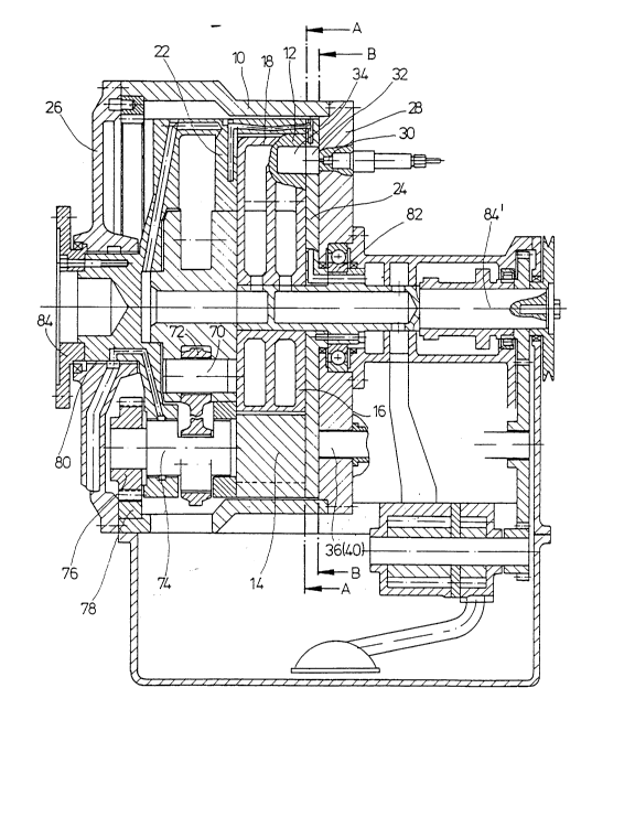
The rotary piston internal combustion engine
consists essentially of a motor housing 10, an outer
rotor 12, which has four pistons 14 arranged at equal
angular distances from one another projecting radially
inwardly, and of an inner rotor 16 rotatably supported
within the outer rotor 12, and rotating with an irregular
speed. The inner rotor 16 with four radially outwardly
projecting winglike opposed pistons 18 is received by the
15 spaces between each two of the pistons 14 of the outer
rotor 20. In the reciprocal area of engagement of the
pistons 14 and of the opposed pistons 18 a total of
eight working chambers 20 are formed, the volume of which
is periodically reduced and enlarged through the back and
20 forth swinging of the opposed pistons 18. The working
chambers 20 are defined on the front side by rotor side
disks 22, 24 connected fixed against rotation to the
outer rotor, whereas the rotor housing 10 is closed off
by housing lids 26, 28 on the front side.
The exemplary embodiments illustrated in the
drawings are Diesel motors, in which the fuel is supplied
through two injection nozzles 30 arranged at an equal
distance from one another in the housing lid 28 on the
drive opposing side. The fuel is injected through the
30 stationary injection nozzles 30 through a total of eight
control windows 32 in the rotor disk 24 on the drive
opposing side into a corresponding number of combustion
chambers 34 in the passing outer rotor 12, after fresh
air was earlier sucked through the inlet openings 36 and
35 the control windows 32 into the associated working
chamber 20 and was compressed by the opposed piston 18 in
the respective combustion chamber 34 to an ignition
- 216717~
temperature. As can be seen in a schematic illustration
in Figures lOa and b, the ignition occurs near the upper
dead center position of the opposed piston 18 when the
outer rotor 12 passes the injection nozzle 30 over a
stretch of approximately 2 to 6 toward the upper dead
center position so that due to the spacial shifting of
the combustion chamber 34 relative to the injection point
30, a good mixing of the fuel with the compressed air
occurs in the combustion chamber. A further contribution
for the good mixing comes from the compressed air 38
flowing from the gap narrowing down in advance of the
dead center position between the piston 14 and the
opposed piston 18 into the combustion chamber 34. The
combustion gases expand after the ignition drives the
pistons 14 and the opposed pistons 18 apart, and
subsequently escape through the control window 32 into
the elongated outlet opening 40, into which a sealed
preoutlet 42 is integrated in order to avoid an overflow
of exhaust gases into the adjacent inlet opening 36. The
outlet openings 40, the inlet openings 36, and the
injection nozzles 30 are arranged on a common inscribed
circle 44 of the housing lid 28 on the drive opposing
side. The arrow 24 (12) indicates in Figure 12 the
direction of rotation of the side disk 24 of the outer
rotor 12.
The control windows 32 can either be circular
(Figures 3 and 4) or can be designed as an oval elongated
in direction of the inscribed circle 46 on the rotor disk
24 (Figures 5 and 6). The combustion chambers 34 are
accordingly designed either as circular-cylinders
(Figures 3 and 4) or oval-cylinders (Figures 5 and 6).
The combustion chambers 34 are each arranged in pairs
parallel to the axis in the pistons 14, so that they are
open at the edge on the side of the piston flanks toward
the adjacent working chamber 20. As can be seen from
Figure 1, they extend only over a portion of the axial
dimension of the outer rotor 12. In the case of the
216717~
exemplary embodiment illustrated in Figure 4, the opposed
pistons 18 have at their flanks at the height of the
combustion chambers 34 partial cylindrical recesses 48.
The cylindrical recesses together with the combustion
5 chambers 34 in the piston 14 form a full cylinder.
The pistons 14 and the opposed pistons 18 have, in
the exemplary embodiment according to Figure 6, flanks
arched complementarily convexly or concavely with respect
to one another, and which result in a desired
protuberance of the combustion chambers 34 near the
flanks.
In order to seal the working chambers 20 and the
associated combustion chambers 34 against one another and
with respect to the housing lid 28, sealing bars 50, 52,
15 54, 56 are arranged in associated grooves on the outside
of the rotor side disk 24 on the drive opposing side.
The sealing bars bridge the gap to the adjacent housing
lid 28 on the drive opposing side. The annular sealing
bars 50 are thereby each arranged concentrically with
20 respect to one of the control windows 32, whereas the
straight sealing bars 52 and 54 connect the adjacent
sealing rings 50 on a radially inner and a radially outer
line and thus define a sealed area for the inlet and
outlet openings 36, 40, by closing off the sealed area to
25 the outside and to the inside. A sealing bar 56 is
arranged centrally between the sealing rings 50 and is
radially aligned, thereby preventing an overflow between
the adjacent outlet and inlet openings 40, 36. In place
of the seals 52, 54 composed of several individual bars,
30 it is possible, in particular in the case of small
motors, to also use one-piece sealing rings, thus
requiring fewer joints.
Also, the inner rotor at its surfaces facing the
rotor disks 22 and 24 has a polygon sealing ring composed
35 of sealing bars 58, 60. This sealing ring enables, in
the area of the acute-angled converging sealing bars 60,
lubrication up to the opposed piston tip. To improve the
2167176
sealing action it is also possible to provide two or more
trains of sealing bars extending parallel side-by-side.
The injection nozzles can be designed either as peg
or hole nozzles aligned parallel to the axis (Figures 1
and 7), or as hole nozzles arranged inclined in the
housing lid (Figure 8). To increase the injection
pressure pump nozzles 62 can also be provided, which can
be operated through a cam plate 64 driven through the
motor shaft 84', a roller shaft 66, and a rocker arm 68.
The relative movement between the inner rotor 16 and
the outer rotor 12 is transmitted with the help of four
connecting rods 72 hinged to bolts 70 of the inner rotor
16 to the four crankshafts 74 and is converted into a
rotary movement. Gears 76, which are connected to the
crankshafts 74 on the front side, mate with the teeth of
an internally toothed annular gear 78, which is connected
to the housing lid 26 on the drive side, and transfer
thus the rotary movement of the crankshafts 74 into a
rotary movement of the outer rotor 12 relative to the
rotor housing 10. The rotor rotation can be transmitted
by means of a driven shaft 84, 84', which is connected in
one piece with the rotor side disk 22 on the drive side,
and is supported on the bearings 80, 82' of the housing
lids 26, 28, onto a consumer.
In conclusion the following is to be stated: A
rotary piston internal combustion engine operating on the
basis of the cat and mouse principle is suggested, in
which the charge is exchanged axially through one of the
housing lids 28 and the adjacent rotor side disk 24. The
combustion chambers 34 are formed in the pistons 24 of
the outer rotor 12 through axially open recesses, which
communicate transversely thereto with the adjacent
working chambers 20. The fuel is supplied in the case of
the Diesel motor through injection nozzles 30, which are
aligned in direction of the rotor side disk 24 in the
respective housing lid 28.