Note: Descriptions are shown in the official language in which they were submitted.
~WO 95103023 PCT/US94108255
21 672 7 1
ABSORBENT ARTICLES HAVING FIXED LENGTH
UNDERGARMENT COVERING COMPONENTS THAT
AUTOMATICALLY WRAP THE SIDES OF UNDERGARMENTS
FIELD OF THE INVENTION
The present invention relates to absorbent articles such as sanitary napkins,
panty liners, and incontinence pads. More particularly, the present invention
relates
to sanitary napkins that have fixed length undergarment covering components
(or
"side wrapping elements") that automatically wrap the sides of a wearer's
undergarments when the undergarments are pulled up which provide an
alternative
to conventional side flaps.
BACKGROUND OF THE INVENTION
Absorbent articles such as sanitary napkins, pantiliners, and incontinence
pads
are devices that are typically worn in the crotch region of an undergarment.
These
devices are designed to absorb and retain liquid and other discharges from the
human
body and to prevent body and clothing soiling. Sanitary napkins are a type of
absorbent article worn by women in a pair of panties that is normally
positioned
between the wearer's legs, adjacent to the perineal area of the body. Sanitary
SUBSTITUTE SHEET (RULE 26~
WO 95103023 PCTlUS94108255
21 672'1 1
napkins both with and without side flaps (or wings) are disclosed in the
literature and
are available in the marketplace.
Generally when sanitary napkins are provided with flaps, the flaps extend
laterally from a central absorbent means and are intended to be folded around
the
edges of the wearer's panties in the crotch region. Commonly, the flaps are
provided
with an attachment means for either affixing the flaps to the underside of the
wearer's
panties or to the opposing flap. The flaps are particularly effective for
preventing
exudates from soiling the edges of the wearer's panties.
Sanitary napkins having flaps of various types are disclosed in U. S. Patent
4,687,478, entitled "Shaped Sanitary Napkin With Flaps", which issued to Van
Tilburg on August 18, 1987; U.S. Patent 4,608,047, entitled "Sanitary Napkin
Attachment Means", which issued to Mattingly on August 26, 1986; U.S. Patent
4,589,876, entitled "Sanitary Napkin", which issued to Van Tilburg on May 20,
1986
and its Reexamination Patent No. B 1 4,589,876, Certificate of Reexamination
issued
April 27, 1993; U.S. Patent 4,285,343, entitled "Sanitary Napkin", which
issued to
McNair on August 25, 1981; U.S. Patent 3,397,697, entitled "Disposable
Sanitary
Shield For Undergarments", which issued to Rickard on August 20, 1968; and,
U.S.
Patent 2,787,271, entitled "Sanitary Napkin", which issued to Clark on April
2,
1957.
While sanitary napkins having flaps are commonly viewed as providing better
protection against soiling as compared to sanitary napkins without flaps, some
women find applying sanitary napkins having flaps to be inconvenient for
various
reasons. For instance, some women find it to be difficult to attach the flaps
to the
underside of the crotch of their panties. This can be due to factors such as
the
tendency for the adhesive fasteners on the flaps to stick to themselves or to
other
parts of the sanitary napkin. As a result, some women still prefer a sanitary
napkin
without flaps. In addition, some women who generally prefer a sanitary napkin
with
flaps, occasionally prefer a sanitary napkin without flaps. Therefore, there
is a need
for a sanitary napkin which provides an alternative to sanitary napkins having
conventional side flaps while still providing the protection of side flaps.
SUBSTITUTE SHEET (RULE 26~
WO 95103023 2 1 6 7 ~ 7
PCTIUS94108255
3
Thus, a need exists for an absorbent article, such as a sanitary napkin, that
is
Several variations of sanitary napkins having conventional flaps that attempt
to
solve some, but not all of these problems are disclosed in the patent
literature. For
example, U.S. Patent 4,911,701 issued to Mavinkurve discloses a sanitary
napkin
having elastic strands for providing a greater convex shape to the body-facing
portion of the central absorbent and for enabling adhesive-free placement of
the flaps
of a winged napkin embodiment into a pair of panties. The sanitary napkin
described
in the Mavinkurve patent, however, still appears to require the user to
manipulate the
flaps (by first flipping the flaps upward and then placing the flaps in her
panties and
flipping the flaps back down) since the flaps appear to be pre-disposed to be
in a
downward folded condition. The Mavinkurve patent also requires that individual
elastic strands be attached in a contracted condition to the central absorbent
portion
of the napkin and/or to its wings or flaps. The napkins described in the
Mavinkurve
patent can, therefore, be difficult and expensive to manufacture. U.S. Patent
4,940,462 issued to Salerno discloses a sanitary napkin with longitudinally
expandable flaps. The flaps are designed to fold over the exterior of the
wearers
panty and then to longitudinally expand to conform with the contour of the
panties.
The Salerno patent, however, appears to require conventional adhesive
fasteners to
retain the flaps in place on the underside of the wearer's panties.
provided with an alternative to conventional flaps. In particular, a need
exists for a
sanitary napkin having an alternative to conventional flaps which provides the
protection from soiling of conventional flaps and which can conveniently and
efficiently solve the problems caused when attempting to attach conventional
flaps to
the underside of the wearer's panties.
It is, therefore, an aspect of an object of the present invention to provide
an absorbent article, such as a sanitary napkin, that is able to provide
coverage to
the wearer's panties to reduce side soiling (i.e., staining of the edges of
the panty
crotch) without the use of conventional flaps.
It is another aspect of the present invention to provide an absorbent
article, such as a sanitary napkin that automatically wraps around the sides
of the
wearer's panties by the simple action of the wearer pulling up her panties.
:'
S~S11ME SHEET (RULE 2~
WO 95/03023
2 ~ s ~ 2. / 1 4 PCTIUS94I08255
It is still another aspect of an object of the present invention to provide an
absorbent article, such as a sanitary napkin, that is able to wrap around the
sides
of the wearer's panties and stay without providing flaps having panty
fasteners
thereon, and without attaching separate elastic strands to the sanitary
napkin.
These and other aspects of objects of the present invention will be more
readily apparent when considered in reference to the following description and
when taken in conjunction with the accompanying drawings.
SL1MMARY OF THE INVENTION
'The present invention provides an absorbent article, such as a sanitary
napkin.
The sanitary napkin of the present invention has undergarment covering
components
(or "side wrapping elements") that automatically wrap the sides of a wearetas
undergarments when the undergarments are pulled up. The sanitary napkcin of
the
present invention provides coverage to the wearer's panties to reduce side
soiling
(i.e., staining of the edges of the panty crotch) without the use of
conventional flaps
which must be manually positioned into their in-use condition.
The sanitary napidn has a longitudinal dimension extending in a longitudinal
direction and a transverse dimension extending in a transverse direction. The
sanitary napkin comprises a main body portion and a pair of side wrapping
elemenu.
The main body portion comprises a liquid pervious topsheei, a liquid
impervious
backsheet joined to the topsheet, and an absorbent core positioned between the
topsheet and the backcsheet. The side wrapping elements comprise a pair of
flexible
elements that are joined to the main body portion and extend laterally outward
beyond the longitudinal side edges of the main body portion to their distal
edges.
The side wrapping elements are pre-disposed to fold around the edges of the
crotch
region of the wearer's undergarments. The side wrapping elements have a fixed
length distal edge that provides the side wrapping elements with a hoop-Like
structure that resists extension and that facilitates automatic flipping or
wrapping of
the side wrapping elements around the edges of the wearers undergarment when
the
undergarment is pulled into its in-use condition. This automatic flipping
action is
.~, , ~r
5~511ME SHEEt (RULE 2b~
21 672 7 1 J
s
facilitated when the main body portion of the sanitary napkin is placed in a
wearer's panties and the main body portion assumes an upwardly arched
configuration along its longitudinal centerline when the panties are pulled
into
contact with the wearer's body.
In accordance with one embodiment, the present invention provides an
absorbent article for wearing in a crotch region of an undergarment, the
absorbent article having a longitudinal dimension extending in a longitudinal
direction and a transverse dimension extending in a transverse direction, the
absorbent article comprising:
a main body portion comprising an absorbent core, the main body portion
having a body-facing side, a garment-facing side, and a pair of longitudinal
side
edges; and
a pair of side wrapping elements joined to the main body portion and
extending laterally outward beyond the longitudinal side edges of the main
body
portion to distal edges characterized in that the side wrapping elements are
pre-
disposed to wrap around an edge of the crotch region of the wearer's
undergarment when the main body portion is placed into an upwardly arcuate
configuration, the side wrapping elements comprising a first region that is
free of
elastic strands and extensible primarily in the transverse direction and a
less
extensible second region disposed laterally outward of the first region that
maintains the side wrapping elements in tension when the first region is
extended
laterally outward.
In one preferred embodiment, the side wrapping elements comprise a first
region and a second region that have different flexibilities. In this
embodiment,
the first region preferably comprises a plurality of spaced apart softened,
flexible
portions of the side wrapping elements that are preferably extensible
primarily in
the transverse direction and are disposed laterally inward of the second
region.
The second region is less soft, less flexible, and preferably less extensible
than
the first region and is disposed along at least a portion of the distal edges
of the
side wrapping elements. The second region of the side wrapping elements
21 672 7 1
Sa
maintains a line of tension along the distal edges of the side wrapping
element
that facilitates the automatic flipping of the side wrapping element around
the side
edges of the wearer's undergarment when the undergarment is pulled into its m-
use condition.
In a second preferred embodiment, the side wrapping elements comprise a
first region that is extensible primarily in the transverse direction and a
less
extensible second region that is disposed between portions of the first
region.
The side wrapping elements in this second preferred embodiment can comprise a
web material having a network of strainable regions formed therein. The less
extensible second region maintains the side wrapping elements in tension when
said first region is extended laterally outward to facilitate automatic
flipping of
the side wrapping elements around the side edges of the wearer's undergarment
as the undergarment is raised into position.
In a third preferred embodiment, the side wrapping elements comprise a
plurality of spaced apart regions or components that are gathered
longitudinally
inward along the distal edges of the side wrapping elements and joined
together.
The longitudinal gathering inward of the regions or components maintains a
line
of tension along the distal edges of the side wrapping element that
facilitates
automatic flipping of the side wrapping element around the side edges of the
wearer's undergarment when the undergarment is pulled into its in-use
condition.
'..: ! ,. ~'e.
i J
WO 95/0 ~ ~ PCTlUS94108255
21 67
The sanitary napkin of the present invention provides an alternative to
sanitary
napkins having conventional side flaps for several reasons. The side wrapping
elements do not extend far enough outward beyond the side edges of the
wearer's
panties to cause any inconvenience to the wearer. The sanitary napkin requires
no
action on the part of the wearer in order to fold the side wrapping elements
under
their panties or to attach the same to their panties. The side wrapping
elements,
therefore, stay in place well enough to cover the sides edges of the wearer's
panties
without affixing them underneath the wearer's panties.
BRIEF DESCRIPTION OF THE DRAWINGS
While the specification concludes with claims particularly pointing out and
distinctly claiming the subject matter which is regarded as forming the
present
invention, it is believed that the invention will be better understood from
the
following description which is taken in conjunction with the accompanying
drawings
in which:
FIG. I is a perspective view of the garment-facing side of one embodiment of
the sanitary napkin of the present invention with the side wrapping elements
folded
over the release paper on the garment-facing side.
FIG. 2 is another perspective view of the sanitary napkin shown in FIG. 1
showing the removal of the release paper and the unfolding of the side
wrapping
elements.
FIG. 3 is a perspective view showing the side wrapping elements of the
sanitary napkin shown in FIG. 1 in their unfolded condition.
FIG. 4 is a cross-sectional view of the sanitary napkin shown in FIG. 3 taken
along line 4-4 of FIG. 3.
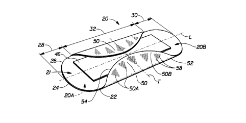
FIG. 5 is a perspective view of the sanitary napkin shown in the preceding
figures, taken from the body-facing side showing the folding of the side
wrapping
elements in use.
SU6STITUTE SHEEP (RULE 26~
'~ WO 95103023 PCT/US94I08?5~
7
~1 672 7 1 v
FIG. SA is a schematic cross-sectional view of the three positions the side
wrapping elements are preferably capable of assuming during wear.
FIG. 6 is a plan view of a second embodiment of the sanitary napkin of the
present invention in which the side wrapping elements comprise a web material
having a network of strainable distinct regions formed therein and reinforced
by a
scrim.
FIG. 7 is an end view of the sanitary napkin shown in FIG. 6.
FIG. 7A is a plan view of a polymeric web material having a strainable
network which is used in the side wrapping elements of the sanitary napkin
shown in
FIGS. 6 and 7 (shown with the deformations facing toward the viewer).
FIGS. 7B-D are enlarged segmented perspective illustrations of the polymeric
web material used in the side wrapping elements of the sanitary napkin shown
in
FIGS.1 6 and 7 moving from an untensioned condition to progressively greater
tensioned conditions.
FIG. 7E shows a schematic cross-sectional view of the side wrapping
element of an embodiment of the napkin in place on the undergarment.
FIG 8. Is a schematic plan view of a portion of an alternative version of
the embodiment shown in FIGS. 6 and 7 in which the distal edge of the side
wrapping element does not have the strainable network formed therein.
FIGS. 9 and 10 are perspective view of a third embodiment of a sanitary
napkin of the present invention in which FIG. 9 shows the formation of side
wrapping elements comprising a plurality of overlapping components that are
gathered together and sealed with a seam and FIG. 10 shows the completed-
formed product.
DETAILED DESCRIPTION FO THE INVENTION
FIGS. 1-5 show one preferred embodiment of a disposable absorbent
article of the present invention, sanitary napkin 20. The present invention
relates
to absorbent articles such as sanitary napkins that have a main body portion
21
and undergarment
SUBSTIME SHEET (RULE.26~
WO 95103023 PCT/US94108255
21 67271
covering cc.-.lponents (or "side wrapping elements") 50 that automatically
wrap the
sides of the wearer's panties when the wearer places the sanitary napkin in
her
panties and pulls her panties up.
The sanitary napkin 20 has two surfaces, a liquid pervious body-contacting
surface or "body surface" 20A that is intended to be worn adjacent to the body
of the
wearer and a liquid impervious garment surface 208. The sanitary napkin 20 is
shown in FIG. 1 as viewed from its garment surface 20B. The body surface 20A
of
the sanitary napkin 20 is intended to be placed adjacent to the wearer's body
when
the sanitary napkin 20 is worn.
The sanitary napkin 20 has two centerlines, a longitudinal centerline L and a
transverse centerline T. The term "longitudinal", as used herein, refers to a
line, axis,
or direction in the plane of the sanitary napkin 20 that is generally aligned
with (e.g.,
approximately parallel to) a vertical plane which bisects a standing wearer
into left
and right body halves when the sanitary napkin 20 is worn. The tenors
"transverse"
or "lateral" used herein, are interchangeable, and refer to a line, axis, or
direction
which lies within the plane of the sanitary napkin 20 that is generally
perpendicular to
the longitudinal direction.
FIG. 1 shows that the main body portion 21 of the sanitary napkin 20
comprises the portion of the sanitary napkin without the side wrapping
elements
in position to wrap around the edge of the crotch of the wearer's
undergarment.
The main body portion 21 has two spaced apart longitudinal edges 22, two
spaced apart transverse or end edges (or "ends") 24, which together form the
periphery 26 of the main body portion of the sanitary napkin 20. The main body
portion also has two end regions, which are designated first end region 28 and
second end region 30. A central region 32 is disposed between the end regions
28
and 30. The end regions 28 and 30 extend outwardly from the edges of the
central region 32 about ll8 to about 1/3 of the length of the main body
portion.
A detailed description of a sanitary napkin having a central region 32 and the
two
end regions 28 and 30 is contained in U.S. Patent 4,690,680 issued to Higgins
on
September 1, 1987.
~~-~ ;:,_
~~~STiME SHEET (RULE 26'~
WO 95103013
PCT/US94108255
21 67271 ~ 9
The main body portion of the sanitary napkin 20 can be of any thickness,
including relatively thick, relatively thin, or even very thin. The embodiment
of the
sanitary napkin 20 shown in Figures 1-5 of the drawings is intended to be an
example
of a relatively thin sanitary napkin, preferably an "ultra-thin" sanitary
napkin as
described in U.S. Patents 4,950,264 and 5,009,653, both issued to Osborn .
The sanitary napkin 20
shown should preferably also be relatively flexible, so that it is comfortable
for the
wearer. It should be understood that the sanitary napkin shown is merely one
preferred embodiment, and that the present invention is not limited to
absorbent
articles of the type or having the specific configurations shown in the
drawings.
FIG. 4 shows the individual components of the main body portion 21 of the
sanitary napkin 20 of the present invention. The main body portion 21
generally
comprises at least three primary components. These include a Liquid pervious
topsheet 38, a liquid impervious backsheet 40, and an absorbent core 42
positioned
between the topsheet 38 and the backsheet 40. There are occasions, however,
when
one or more of these components, such as the backsheet, can comprise part of
the
side wrapping elements described herein. The topsheet, the backsheet, and the
absorbent core may be assembled in a variety of configurations known in the
art
(including so called "sandwich" products and "tube" products).
Several preferred sanitary napkin configurations are described generally in
U.S. Patent 4,321,924, "Bordered Disposable Absorbent Article" issued to Ahr
on
March 30, 1982; U.S. Patent 4,425,130, "Compound Sanitary Napkin" issued to
DesMarais on January 10, 1984; U.S. Patent 4,950,264, "Thin, Flexible Sanitary
Napkin" issued to Osborn on August 21, 1990; U.S. Patent 5,308,346,
"Elasticized
Sanitary Napkin" issued to Sneller, et al. on May 3, 1994; U.S. Patent
No. 5 5 8 4 8 2 9 entitled "Absorbent Articles Having Panty Covering
Components That Naturally Wrap the Sides of Panties" ;
and CA Patent Application Serial No. 217 0 4 9 2 entitled
"Absorbent Articles Having Panty Covering Components Comprising Extensible
Web Materials Which Exhibit Elastic-Like Behavior" .
The main body portion 21 of the sanitary napkin may
also be comprised of one or more extensible components such as those sanitary
I,.Caa .Y
:~';~ii : ~ ~.,'~
~SnME SHEET (RULE.26~
",..,, WO 95103023 PCTIUS94f08255
21 67271
napkins, and the like described in
PCT
Publication Nos. WO 93101785 and 93/01786, both published February 4, 1993.
The sanitary napkin 20, as shown in FIG. 4, is assembled in a sandwich
construction in which the topsheet 38 and the backsheet 40 have length and
width
dimensions generally larger than those of the absorbent core 42. The topsheet
38
and the backsheet 40 extend beyond the edges of the absorbent core 42 to form
portions of the periphery 26. The sanitary napkin 20 of the present invention
comprises a pair of side wrapping elements 50 joined to the main body portion
21
that extend from proximal edges 52 laterally outward beyond the longitudinal
side
edges 22 of the main body portion 21 to their distal edges 54. The term
"joined", as
used herein, encompasses configurations in which an element is directly
secured to
another element by affixing the element directly to the other element;
configurations
in which the element is indirectly secured to the other element by affixing
the element
to intermediate members) which in turn are affixed to the other element; and
configurations in which one element is integral with another element, i.e.,
one
element is essentially part of the other element.
The side wrapping elements 50 can be of any suitable size and shape. The side
wrapping elements 50 can be as large as any of the flaps described in the
patents set
out in the Background of the Invention, which are hereby incorporated by
reference
herein. Preferably, however, the distal edges 54 of the side wrapping elements
preferably extend outward beyond the longitudinal side edges 22 of the main
body
portion 21, a distance of less than one-half the width of the main body
portion so
that they do not extend far enough outward beyond the side edges of the
wearer's
panties to cause any inconvenience to the wearer. The side wrapping elements
50 of
the present invention preferably have the dimensions set forth for the panty
covering
components in the aforementioned U. S. Patent No . 5 . 5 8 4 . 8 2 9 and
Canadian Patent Application rlo. 2.170,492,
The side wrapping
elements 50 can be made from any of the materials suitable for use in the
conswction of the main body portion 21 of the sanitary napkin. The side
wrapping
...;~ _ ;ft
SUBSTITUTE SHEFf (RULE 26)
'~;~VO 95103023 11 ~ ~ ~ ~ P~~S~4108255
elements can comprise absorbent materials if the side wrapping elements are
suitably
sealed to prevent wicking of exudates from their distal edges 54. Preferably,
however, the materials comprising the side wrapping elements are substantially
non-
absorbent.
The side wrapping elements 50 preferably have a resistance to edge
compression so that they will fold rather than crumple when placed in a
wearer's
panties and subjected to the forces associated with wearing the sanitary
napkin. The
term "resistance to edge compression" refers to how substantial the material
that
comprises the side wrapping elements 50 is. Specifically, edge compression
refers to
the tendency of the side wrapping elements 50 to buckle when the side wrapping
elements are extended to form a planar extension and forces are applied to the
distal
edge 54 of the side wrapping element by a plate oriented perpendicular to the
plane
of the side wrapping elements 50. This property is important because if the
side
wrapping elements 50 are insubstantial, they will bunch up when forces are
applied
to the side wrapping elements by the wearer's panty elastics or by the
wearer's thighs
during wear. The side wrapping elements 50 should, of course, not be so stiff
that
they are uncomfortable to the wearer.
In the preferred embodiment of the present invention shown in FIGS. 1-5, the
side wrapping elements 50 are provided with first regions SOA comprising
softened,
flexible and preferably extensible regions (or "portions") of the side
wrapping
elements 50 and a second region (or "distal edge portion") SOB that is less
soft, less
flexible (i.e., stiffer), and preferably less extensible than the first
regions SOA. The
side wrapping elements 50 are pre-disposed to fold around the side edges of
the
crotch region of the wearer's undergarments. The second region SOB of the side
wrapping elements 50 maintains a line of tension along the distal edges 54 of
the side
wrapping elements 50 that facilitates automatic flipping of the side wrapping
elements 50 around the side edges of the wearer's undergarment when the
undergarment is raised into position.
The first and second regions SOA and SOB of the side wrapping elements can
have many possible shapes and arrangements. The first region SOA may comprise
a
single region, or a plurality of regions or portions of the side wrapping
elements. If
SU8ST1TUTE SHEET (RULE 26~
WO 95/03023 PCTIUS94108255
~ s~ 2? ~ ~ l2
the first region SOA comprises a plurality of portions of the side wrapping
elements,
these portions of the side wrapping elements may be interconnected or they may
be
spaced apart. Regardless of the arrangement and shape used, the first regions
SOA
are preferably positioned inboard of the distal edges 54 of the side wrapping
elements. The first regions SOA are preferably far enough inboard of the
distal edges
54 of the side wrapping elements that the side wrapping elements 50 each have
a
second region SOB that comprises a band of substantially inextensible,
unsoftened
material that is disposed along at least a portion of, and preferably along
all of the
distal edge 54 of the side wrapping elements. This allows the distal edges 54
of the
side wrapping elements to function in effect like a hoop that retains a
constant length
which assists the side wrapping elements 50 in automatically wrapping around
the
edges of the wearer's panty crotch. This automatic wrapping action is
facilitated
when the main body portion of the sanitary napkin is placed in a wearer's
panties and
the main body portion assumes an upwardly arched configuration along its
longitudinal centerline when the panties are pulled into contact with the
wearer's
body. The arching of the main body portion places tension on the distal edges
54 of
the side wrapping elements 50. This causes the side wrapping elements 50 to
fold
under the panties since the side wrapping elements will tend to assume a
configuration that is closest to a straight line (between the ends of the
arching main
body portion) when they are under tension.
In the preferred embodiment shown in FIGS. 1-5, the first regions SOA
comprise a plurality of spaced apart triangularly-shaped regions of the side
wrapping
elements 50 that are softened and provided with increased flexibility. The
first
regions SOA are oriented so that the apex (that is, the narrowest portion) of
the
triangularly-shaped areas is closest to the proximal edges 52 of the side
wrapping
elements, and the bases (or widest portions) of the triangularly-shaped areas
are
closer to the distal edges 54 of the side wrapping elements. This allows for
greater
reduction of the stresses in the side wrapping elements near the distal edges
of the
side wrapping elements. The reduction of stresses is, thus, at those locations
where
the stresses are the greatest when the side wrapping elements 50 are folded
around
the crotch region of a panty.
SUBSTITUTE SHEEP (RULE 26~
,,... WO 95103023
PCT/US94I0825~
13 21 67 2 7 1
The side wrapping elements 50 can be provided with first and second regions
SOA and SOB in a non-limiting number of different manners. The side wrapping
elements 50 may, far example, comprise a substantially inextensible material
that is
provided with mechanically softened or extensible regions inboard of the
distal edges
54 of the side wrapping elements for the first regions SOA. The mechanically
softened or extensible regions can be created in any suitable manner,
including but
not limited to mechanically straining, convgating, "ring rolling", heating and
deforming, subjecting to compression between mating plates, and the like.
In other alternative embodiments, the different regions of the side wrapping
elements can be provided by forming the side wrapping elements 50 out of
materials
having different properties. For example, the side wrapping elements 50 can be
comprised of a laminate of an extensible material and an inextensible
material. In
such an embodiment, the inextensible material can be provided in the
configuration
of the side wrapping elements 50, but have holes cut out where the first
regions SOA
are to be located, which is then laminated to the extensible material.
Alternatively,
the side wrapping elements 50 can comprise a generally extensible material
that has a
strip of inextensible material attached along or wrapped around the portion of
the
extensible material that will form the distal edge 54 of the side wrapping
element.
The embodiment shown in FIGS. 1-5 has first regions SOA that are preferably
either formed by ring rolling (or pre-convgating) or by forming a strainable
network
in five separate regions of each of the side wrapping elements 50. The first
regions
SOA preferably have convgations or deformations with ridges (or fold lines) 58
that
are generally oriented in the longitudinal direction. The side wrapping
element 50
may fold through a large number of combinations of these longitudinally-
oriented
ridges or fold Lines. This allows the side wrapping elements 50 to accommodate
panties having different sizes and shapes. Suitable methods for ring rolling
are
described in U.S. Patent 4,107,364 issued to Sisson on August 15, 1978, U.S.
Patent
4,834,741 issued to Sabee on May 30, 1989, U.S. Patent 5,143,679 issued to
Gcraid
M. Weber, et al. on September 1, 1992, U.S. Patent 5,156,793 issued to Kenneth
B.
Buell, et al, on October 20, 1992, and U.S. Patent 5,167,897 issued to Gerald
M.
Weber, et al. on December 1, 1992 .
~ z.~..' S'U8ST1TUTE SHEET (RULE 26'~
WO 95103023 PCTIUS94108255
14
21 ~7 2 7 1
reference _herein). The formation of a strainable network into a web material
is
described below in conjunction with the embodiments shown in FIGS. 6-8.
The first regions SOA in this embodiment are preferably extensible in a
direction perpendicular to the fold lines 58 of the corrugations or
deformations. The
first regions SOA are preferably primarily extensible in the transverse
direction. The
phrase "primarily extensible in the transverse direction" means that the first
regions
SOA are preferably more extensible in the transverse direction than in the
longitudinal
direction. However, the first regions SOA can also be primarily extensible in
the
longitudinal direction, or in any direction between the longitudinal direction
and the
transverse direction. If there is more than one first region SOA, the
extensibility of
different first regions SOA can all be in the same direction. Alternatively,
one or
more of the first regions SOA may have an extensibility in a different
direction.
The garment surface 20B of the sanitary napkin 20 may include, and preferably
does include, fasteners for attaching the sanitary napkin to the wearer's
undergarments. Figure 2 shows the central pad fastener 44 which is adapted to
secure the main body portion 21 of the sanitary napkin to the crotch region of
an
undergarment. Fasteners comprising adhesives have been found to work welt for
this purpose, with pressure sensitive adhesives being preferred. Before the
sanitary
napkin 20 is placed in use, if an adhesive fastener is used, the adhesive is
typically
covered with a removable cover strip or release liner 46 in order to keep the
adhesive
from sticking to a surface other than the crotch portion of the panty prior to
use.
Suitable release liners are described in the U.S. Patent 4,917,697.
The sanitary napkin 20 of the present invention is used by removing any
release liner and thereafter placing the sanitary napkin 20 in a panty so that
the
adhesive (or other fastener) 44 contacts the inside surface of the crotch
region of the
panty and maintains the sanitary napkin in position within the panty during
use. The
side wrapping elements 50 automatically wrap around the sides of the wearer's
panties when the main body portion 21 of the sanitary napkin is placed in a
wearer's
panties and the main body portion assumes an upwardly arched configuration
along
its longitudinal centerline as shown in FIG. 5 when the panties are pulled
into contact
with the wearer's body.
SUBSTITUTE SHEET (RULE 26~
O 95103023 PCTIUS94/08255
2't 67271
FIG. 5A shows that the side wrapping elements 50 are preferably capable of
assuming three distinct positions when the sanitary napkin 20 is placed in a
wearer's
undergarments U during wear. These comprise: (a) a first stable position in
which
the side wrapping elements 50 extend generally outward from the main body
portion
21; (b) an unstable position in which they are partially folded toward the
garment-
facing side of the main body portion; and, (c) a second stable position in
which said
side wrapping elements form an acute angle with the garment-facing side of
said
main body portion.
The first stable position can be a position such as that designated position
(1)
in which the side wrapping elements 50 extend straight out from the sides of
the
main body portion 21. That is, the side wrapping elements form an angle of
180°
with a plane, P, which passes through a section of the main body portion taken
along
the transverse centerline of the sanitary napkin. (It is understood, however,
that the
main body portion, per se, will typically be in a curved or folded overall
configuration, rather than planar configuration.) In alternative embodiments,
the side
wrapping elements 50 may have a first stable position such as that designated
position ( 1 A) where the side wrapping elements 50 initially form an obtuse
angle (A)
relative to the plane, P, of the section of the main body portion taken along
the
transverse centerline. The embodiment shown in FIGS. 1-5 can serve as an
example
of an embodiment in which the side wrapping elements 50 may form an obtuse
angle
with respect to the plane of the main body portion in their first stable
position. When
forces F are applied to the side wrapping elements 50 in the direction of the
arrows
in FIG. 5A (such as by the wearer's thighs W), the side wrapping elements 50
move
to an unstable position (2). The side wrapping elements 50 are typically in an
unstable position at all locations between positions (lA) and (3). An unstable
position may, for example, be approximately at a 90° fold angle
relative to the plane
P. The side wrapping elements 50 preferably then have a tendency to flip to
their
second stable position, position (3). In their second stable position, the
side
wrapping elements 50 fold more toward the garment-facing side of the main body
portion, and preferably form an acute angle with the garment-facing side of
the main
body portion. The side wrapping elements 50 will typically fold smoothly
through
the three positions referred to herein so that the precise place where one
position
SU85TITUTE SHEET (RULE 2~
WO 95103023 ~ PCT/L1S94108255
16
ends and another begins may blend into one another. It should also be
understood
that FIG. SA is primarily presented for purposes of illustration of the
concepts
referred to herein. The present invention is, therefore, not intended to be
limited to
absorbent articles having side wrapping elements 50 that assume the exact
positions
shown in FIG. 5 A.
The operation of the side wrapping elements 50 is distinguishable in several
respects from that of conventional side flaps. Placing a sanitary napkin
having
conventional flaps in a pair of panties and pulling up the panties will not
consistently
provide the automatic sustained wraparound feature of the present invention.
There
are several reasons for this. Conventional flaps do not have a distal edge
that is
maintained in tension that facilitates automatic flipping of such flaps around
the side
edges of a wearer's undergarment when the undergarment is pulled into its in-
use
condition. Conventional flaps are also not provided with resistance to edge
compression so that they will tend to crumple in use, particularly when the
wearer's
thighs exert compressive forces on the flaps. Conventional flaps also do not
retain a
high degree of their fold, so that in cases where conventional flaps do wrap
around
the panties, they will not consistently stay wrapped. By contrast, once the
side
wrapping elements of the present invention are folded, the upward arching of
the
main body portion tends to increase tension in the distal edge, thereby
locking the
pad in its in-use condition. In addition, conventionally-sized flaps will have
excess
flap material that hangs down underneath the panties during wear. This
material can
move around excessively underneath the panties. The side wrapping elements of
the
present invention, on the other hand, have a span that is ideally just wide
enough to
wrap around the elastic-containing edges of the panties, but no wider,
avoiding the
problems associated with excess flap material.
The sarutary napkin 20 of the present invention can be provided with still
other
features to assist in positioning the side wrapping elements 50 in the
wearer's panties.
The side wrapping elements 50 shown in FIGS. 1-5 are initially folded toward
the
garment-facing side 20B of the sanitary napkin and over the top of the release
paper
46 that protects the securement adhesive 44 on the back of the sanitary
napkin. FIG.
2 shows that if the side wrapping elements SO and the release paper 46 are
properly
sized in relation to one another, stripping away the release paper 46 can
serve to
SUBSTITUTE SHEET (RULE 26~
""""VO 95/03023 PCTIUS94/08255
21 672 7 9 ~ 1'
automatically unfold the side wrapping elements 50 from the back of the
sanitary
napkin and cause the side wrapping elements 50 to project generally outwardly
in the
desired orientation for installation of the sanitary napkin in the
undergarment. FIGS.
3 and 4 show that when the release paper 44 is removed, there will be a
tendency for
the side wrapping elements 50 to automatically return part of the way to their
original folded over condition because the material comprising the side
wrapping
elements 50 will retain memory of the original folded over condition due to
the
residual stresses resulting from the folding. The sanitary napkin is then
placed into
the wearer's panties and the panties are pulled into the desired wearing
position.
Pulling the panties up against the wearer's body will force the main body
portion 21
of the sanitary napkin into an arc. This will cause the inextensible perimeter
of the
side wrapping elements to experience tension and will cause the side wrapping
elements 50 to collapse around the panty crotch.
Another variable which can be used to assist in positioning of the side
wrapping elements 50 in a preferred orientation for installation in the
wearer's panties
is the packaging of the sanitary napkin in an individual wrapper. For example,
a
sanitary napkin in the embodiment shown in FIGS. 1-5 can be tri-folded and
placed
in an individual package so that it can be kept clean while it is carried by
the user in
her purse. If the sanitary napkin is tri-folded inwardly over the backsheet,
this will
make the side wrapping elements 50 pre-disposed to fold toward the backsheet
when
they are removed from the package and placed in the wearer's undergarment.
That
is, the folding of the sanitary napkin might be used to bias the side wrapping
elements 50 into a configuration that would make its final position easier to
achieve
without any conscious act on the part of the user. It should also be
understood that
this feature and the preceding additional feature can be employed in
conjunction with
any of the other embodiments described below.
FIGS. 6 and 7 show a second preferred embodiment of a sanitary napkin 20 of
the present invention. In this embodiment, the side wrapping elements 50
comprise a
first region SOA that is distributed throughout the entirety of the side
wrapping
elements 50. The side wrapping elements 50 are primarily extensible in the
transverse direction (shown by the arrows). The side wrapping elements 50 also
comprise less extensible second regions SOB. The second regions 50B are
disposed
SUBSTITUTE SHEET (RULE 26~
.... WO 951030?3
PCT/US94108255
1g 2~ 67271
throughou ~nd between portions of the first res_tion SOA. The less extensible
second
regions SOB maintain the side wrapping elements 50 in tension when the first
region
SOA of the side wrapping element 50 is extended laterally outward. This
facilitates
the flipping of the side wrapping elements around the side edges of the
wearer's
undergarment.
The side wrapping elements 50 shown in FIGS. 6 and 7 preferably comprise a
web material 60 having a network 62 of strainable regions formed therein that
exhibits an elastic-like behavior in the direction of elongation without the
use of
added elastic materials. This web material may be referred to herein as a
"strainable
web material" for brevity. In the embodiment shown in FIGS. 6 and 7, the
strainabie web material 60 comprises a laminate of an extensible nonwoven
material,
an apertured formed film, and a polyethylene film backshect material. The
extensible
nonwoven material should be oriented so that its extensibility is in the
lateral
direction. The apertured formed film is preferably an apenured film known as
DRI-
WEAVE* which is used as a topsheet on sanitary napkins manufactured by the
Procter & Gamble Comparry, Cincinnati, Ohio under U.S. Patents 4,342,314
issued
to Radel, et al. and 4,463,045 issued to Ahr, et al. The polyethylene
backsheet
material can be an ordinary backsheet material, and preferably has a caliper
of about
1 mil.
FIGS. 7A and 7B are enlarged views of a web material with a strainable
network therein such as that shown in FIGS. 6 and 7. FIGS. 7A and 7B are
simplified in that they illustrate the concept of the strainable network in
one of the
components of the laminate, the film backsheet material. The web material 60
will
be described accordingly in FIGS. 7A and 7B, although it is understood that in
the
embodiment shown in FIGS. 6 and 7, the web material comprises two additional
components. The strainable web material 60 is shown in FIGS. 7A and 78 in its
substantially untensioned condition. The strainable web material 60 has a
longitudinal centerline, L 1, and a lateral centerline, T 1. The lateral
centerline, T l, is
8~~y p~P~~~l~ to the longitudinal centerline, L 1.
FIGS. 7A and 7B show that the strainable web ma- Trial 60 includes a
strainsble network 62 of at least two distinct and dissimilar ~ agions. The
term
* Trade-mark
~ ,.:, 3~r~
.~''~ y'~~,
SUBSTITUTE SHEET (RULE.2~
WO 95103023 PCTIUS94I08255
19 21 872 71
"strainable network", as used herein, refers to an interconnected and
interrelated
group of regions which are able to be extended to some useful degree in a
predetermined direction. The two distinct regions provide the strainable web
material 60 with a first elastic-like, relatively low resistive force stage
and a second
relatively high resistive force stage. The strainable network 62 described
herein is
formed into the web material. As used herein, the term "formed" refers to the
creation of a desired structure or geometry upon the web material that will
substantially retain the desired structure or geometry when it is not
subjected to any
externally applied elongations or forces. Suitable methods for forming a
strainable
network described herein into a material include, but are not limited to
embossing by
mating plates or rolls, thermoforming, high pressure hydraulic forming, or
casting.
FIGS. 7A and 7B show that the two distinct regions of the strainable
network 62 include at least a first region 64 and a second region 66. The
first region
64 will exhibit resistive forces in response to an applied axial elongation
before a
substantial portion of the second region 66 develops significant resistive
forces to the
applied elongation. The second region 66 has a surface-pathlength which is
greater
than that of the first region 64. The surface-pathlengths are measured
substantially
parallel to the predetermined axis while the material is in an untensioned
condition.
The second region 66 includes one or more deformations 74 which extend beyond
the plane of the first region 64. The first and second regions each have a
first surface
and an opposing second surface. In the preferred embodiment shown in FIGS. 7A
and 7B, the strainable network 62 includes a plurality of first regions 64 and
a
plurality of second regions 66. In the preferred embodiment shown in FIGS. 7A
and
7B, the first regions 64 are substantially planar regions. That is, the
material within
the first region 64 is in substantially the same condition before and after
the
formation step undergone by strainable web material. The second regions 66
include
a plurality of continuous, interconnected, deformations 74 which extends
alternately
beyond the plane of both the first and second surfaces (64A and 64B,
respectively)
of the first region 64. In other embodiments, the deformations 74 may extend
beyond the plane of only one of either the first or the second surfaces of the
first
region.
SUBSTITUTE SHEET (RULE 26~
io i i
WO 95103023 - PCTIUS94108255
21~
The first regions 64 have a first axis 68 and a second axis 69, wherein the
first axis 68 is preferably longer than the second axis 69. The first axis 68
of the first
region 64 is substantially parallel to the longitudinal axis, L1, of the
strainable web
material 60 while the second axis 69 is substantially parallel to the
transverse axis,
T 1, of the strainable web material 60. The second regions 66 also have a
first axis
70 and a second axis 71. The first axis 70 of the second region 66 is
substantially
parallel to the longitudinal axis L 1 of the strainable web material 60, while
the
second axis 71 is substantially parallel to the transverse axis T 1 of the
strainable web
material 60. In the preferred embodiment of FIG. 7A, the first regions 64 and
the
second regions 66 are substantially linear, extending continuously in a
direction
substantially parallel to the longitudinal axis L 1 of the strainable web
material. In the
preferred embodiment shown in FIGS. 6 and 7, the longitudinal centerline L1 of
the
strainable web material 60 is generally aligned with the transverse centerline
of the
sanitary napkin 20. In other embodiments, however, the longitudinal centerline
L1
of the web material can be oriented in other directions, depending on the
direction of
extensibility desired.
The strainable web material 60 preferably comprises at least one component
which is a formed polymeric film. The strainable web material 60 can be made
of a
base film material that has a relatively low extensibility under the forces
the sanitary
napkin is normally subjected to when worn. When formed into the strainable web
material as described 60 herein, however, the base material will be extensible
under
the forces the sanitary napkin is normally subjected to when worn. The
strainable
web material 60 is preferably comprised substantially of linear low density
polyethylene (LLDPE). The strainable web material 60 may also be comprised of
other polyolefins such as polyethylenes, including low density polyethylene
(LDPE),
ultra low density polyethylene (LJLDPE), high density polyethylene (HDPE), or
polypropylene and blends thereof with the above and other materials. Examples
of
other suitable polymeric materials which may also be used include, but are not
limited to polyester, polyurethanes, compostable or biodegradable polymers,
heat
shrink polymers, thermoplastic elastomers, and breathable polymeric
structures.
FIGS. 7B, C and D show the manner in which the strainable web material 60
exhibits at least two significantly different stages of controlled resistive
force to
SUBSTITUTE SHEET (RULE 26~
WO 95103023 PCT/US94I08255
21 21 672 ~ 1
elongation when subjected to an applied elongation in a direction parallel to
a
predetermined axis. The strainable web material 60 exhibits first resistive
forces to
the applied elongation (which develop between the stage shown in FIG. 7B and
the
stage shown in FIG. 7C). The first resistive forces occur until the elongation
of the
web is sufficient to cause a substantial portion of the second region 66, to
enter the
plane of applied elongation, as shown in FIG. 7C. After the strainable web
material
60 reaches the stage shown in Fig. 7C, it exhibits a second stage of resistive
forces to
further elongation (as illustrated by FIG. 7D). Typically, when used in the
side
wrapping elements 50 of the present invention, the web material will be within
the
first stage of resistance to elongation so the various portions of the
strainable web
material 60 will only extend to the stage shown in FIG. 7C and adjust so as to
relax
back to the stage shown in FIG. 7B.
The depth and number of deformations 74 in the strainable web material 60
can be varied to control the applied force or elongation required to extend
the web
material used in the side wrapping elements 50. In one preferred embodiment,
the
deformations 74 are formed by two rigid plates having outer dimension of 5.0"
by
12" by 0.75". On one surface of each plate are a series of meshing teeth which
are
substantially triangular in cross section and measure 0.030" at their bases
and taper
to a vertex with a radius of 0.008" at the top. The centerlines of the teeth
are spaced
evenly and at 0.030" increments. On the "toothed" side of one plate, a series
of
grooves are cut which are parallel to each other and perpendicular to the
evenly
spaced teeth. These grooves measure 0.031 " wide and are continuous over the
entire length of the plate, and are spaced at a distance of 0.25" on center.
These
grooves correspond to the undeforned regions of the deformed web of material.
The preferred web material is placed between the plates in a hydraulic press
having
platens larger than the plates to evenly distribute pressure. The plates are
compressed under a load of at least 4,000 pounds. The formed web material is
then
removed from between the plates. The available stretch or elongation is
increased if
for a given number of deformations, the height or degree of deformation
imparted on
the deformations is increased. Similarly, the available stretch or elongation
is
increased if for a given height or degree of deformation, the number or
frequency of
deformations is increased.
SUBSTITUTE SHEET (RULE 26~
it i i,
WO 95/03023 PCTIUS94108255
22
2~ s~2~ ~
The embodiment shown in FIGS. 6 and 7 uses controlled stresses in the
different regions of the strainable web material 60 to cause the side wrapping
elements 50 to curl around to enclose the edges of the panty. This is
desirable, as it
may offer performance like a conventional wing but without wing or flap
adhesives.
FIG. 7E shows one configuration the side wrapping element 50 might take.
However, the stress which causes this curling to occur may also cause the side
wrapping element 50 to occasionally curl too much (as shown by the side
wrapping
element 50' in FIG. 7E) and slip away from the panty, losing coverage of the
edges
of the panty. Therefore, the side wrapping elements SO must also resist the
tendency
to curl excessively. This may be controlled by the stiffness of the materials
forming
the side wrapping elements 50. One way to control the stiffness of the side
wrapping
elements 50 to prevent curling is to add a reinforcing element such as a scrim
82 to
the side wrapping elements 50.
FIG. 8 shows an alternative embodiment of the sanitary napkin shown in
FIGS. 6 and 7. The sanitary napkin shown in FIG. 8 has a strainable network 62
formed into only a portion of the area of its side wrapping element. The
strainable
network 62 is formed so that a portion of the side wrapping element 50 along
the
distal edge 54 of the side wrapping element is not "formed". The embodiment
shovm
in FIG. 8 has the advantage of increasing the tension along the distal edge 54
of the
side wrapping element 50 to facilitate the automatic folding of the side
wrapping
elements 50 when the undergarment is pulled into its use condition. This may
also
make the distal edge 54 stiffer, reducing the tendency for the side wrapping
element
50 to curl under the wearer's undergarment.
FIGS. 9 and 10 show a third basic embodiment of the sanitary napkin of the
present invention. The embodiment shown in FIGS. 9 and 10 has side wrapping
elements 50 that comprise a plurality of spaced apart regions or components
that are
gathered longitudinally inward along the distal edges 54 of the side wrapping
elements SO as shown in FIG. 9 and joined together. The spaced apart regions
or
components are shown in FIGS. 9 and 10 as comprising separate overlapping side
wrapping element components 90A, 90B, and 90C. The side wrapping element
components 90A, 90B, and 90C are gathered longitudinally inward along the
distal
edges 54 of the side wrapping elements SO as shown in FIG. 9 and joined
together by
SUBSTITUTE SHEEP (RULE 2b~
""'WO 95103023 - PCTIUS94108255
23 2~ g72 71
two seams 92 as shown in FIG. 10. This embodiment eliminates any bunching or
puckering that would ordinarily be associated with gathering such structures
using
elastic strands.
In alternative versions of this embodiment, instead of comprising overlapping
components, the regions of components of the side wrapping elements 50 that
are
gathered can be separate components that are non-overlapping, or they can
merely
be different regions of a single component side wrapping element. The regions
or
components of the side wrapping elements 50 can be gathered inward either
before
or after the side wrapping elements 50 are joined to the main body portion 21
of the
sanitary napkin. Gathering of the side wrapping elements 50 may, however, be
somewhat easier to accomplish before the side wrapping elements are joined to
the
main body portion 21 when the side wrapping elements 50 are in the form of a
continuous web.
The gathering inward of the regions or components 90A, B and C of the side
wrapping elements 50 maintains a line of tension along the distal edges 54 of
the side
wrapping elements 50. This line of tension facilitates the flipping of the
side
wrapping elements 50 under the wearer's undergarment. This flipping action is
further facilitated when the main body portion 21 of the sanitary napkin is
placed in a
wearer's panties and the main body portion 21 assumes a curved configuration
when
the panties are pulled up into contact with the wearer's body. In an
alternative
version of this third embodiment, the spaced apart regions or components of
the side
wrapping elements can be gathered longitudinally inward along the proximal
edges
52 of the side wrapping elements to create a different effect.
There are numerous possible alternative embodiments and variations of the
present invention shown in the preceding drawing figures. For example, the
side
wrapping elements are preferably mirror images of each other, and are
symmetrical
about the longitudinal centerline. However, it should be understood that the
shape
and location of the side wrapping elements described herein are those of a
preferred
embodiment, and other embodiments are also possible. In addition, while the
side
wrapping elements 50 are shown as extending from each longitudinal edges of
the
main body portion, in other alternative embodiments, there may only be one
side
SUBSTITUTE SHEET (RULE 2~
.~"'° WO 95/03023 24 ~ 1 PCTILTS94108255
672 7 1
wrapping element extending from one of the edges of the main body portion. The
side wrapping elements 50 may be offset along the longitudinal centerline more
towards one end edge of the main body portion than the other. In still other
embodiments, the side wrapping elements 50 may be separate elements that are
joined underneath to the main body portion 21 of the sanitary napkin inboard
of the
longitudinal side edges 22 of the main body portion. The side wrapping
elements 50,
in such a case, may be otherwix unattached to the garment-facing side of the
main
body portion 21 of the sanitary napkin 20 between the points of attachment and
the
longitudinal side edges 22 of the main body portion.
Th~~ present invention is also applicable to other pes of absorbent articles
worn in the crotch region of an undergarment such as : ~ntiliners and
incontinence
articles. The terms "panty liner" or "pantiliner" refer to absorbent articles
that are
less bulky than sanitary napkins which are generally worn by women between
that
menstrual periods. Examples of suitable absorbent articles in the form of
pantiliners
that can be provided with the side wrapping elements described herein are
disclosed
in U.S. Patent 4,738,676 entitled "Pantiliner" issued to Osborn on April 19,
1988 .
The term "incontinence article" refers to pads, undergarments (pads held in
place by a suspension system of same type, such as a belt, or the like),
inserts for
absorber: articles, capacity boosters for absorbent articles, briefs, bed
pads, and the
Iike, regardless of whither they are worn by adults or other incontinent
persons.
Examples of suitable incontinence articles that can be provided with the side
wrapping elements destxibed herrin are discloxd in U.S. Patent 5,300,054
issued to
Feint, et al. on April 5, 1994 and U.S. Patent 5,304,161 issued to Noel, et
al. April
19, 1994 .
While particular embodiments of the present invention havc been illustrated
acrd described, it would be obvious to thox skilled in the art that various
other
changes and modificuions can be made without departing from the spirit and
scope
of the imrention.
..,
S~8ST1TUTE SHEET (RULE 26y