Note: Descriptions are shown in the official language in which they were submitted.
WO95/027182 1 6 7 ~ 7 8 PCT~S94107589
TITLE
Aqueous-Quench Spinning of Polyamides
BACKGROUND OF THE INVENTION
5Polyamide yarns for textile and carpet end-uses
are typically melt-spun, quenched in air, and drawn after
the yarn is quenched. The drawing step requires a number
of draw rolls and related drive and control systems which
increases the complexity of the spinning machine and the
manufacturing process. While it is possible to use
processes in which the yarn is spun at sufficiently high
speeds that a "fully-drawn" yarn can be made without a
drawing step, sophisticated equipment is needed and the
desired yarn properties are difficult to achieve. The
present invention permits the use of simpler spinning
machines which take up less floor space. Also, because of
less tension on the threadline, fewer breaks and higher
yields can be expected.
SUMMARY OF THE INVENTION
In accordance with the invention, a novel process
is provided which can produce a "fully-drawn" polyamide
yarn without the need for drawing. The process includes
extruding molten polyamide from spinneret capillaries
through a gas-filled gap and into a quench bath which
contains an aqueous liquid at a temperature of at least
45C. Below the surface of the bath is a nozzle defining
a cylindrical passageway disposed in a generally vertical
position with entrance opening in the bath. The filaments
are converged into a bundle at the entrance to the nozzle
passageway and are removed from the bath at the other end
of the passageway along with entrained bath liguid. The
filament bundle is withdrawn from the bath at a speed of
about 1500 to about 3500 meters per minute (m/min). The
ratio of the withdrawal speed (m/min.) of the filament
bundle from the exit of the nozzle passageway to the jet
velocity, that is, the draw-down ratio, should be from lO
to 50.
WO95/02718 2 1 ~ 7 3 7 8 PCT~S94/07~89
BRIEF DESCRIPTION OF THE DRAWINGS
Figure 1 is a schematic elevational view of a
process in accordance with the present invention;
Figure 2 is a schematic side view of quenching
apparatus useful in a process as illustrated in Figure 1.
DETAILED DESCRIPTION
Polyamide as used in this application refers to
any of the various generally linear, aliphatic homo- and
co-polyamides which are typically melt-spinnable and which
yield fibers having properties suitable for the intended
application. For this invention, poly(hexamethylene
adipamide) (6,6 nylon) and poly(~-caproamide) (6 nylon),
and their copolymers are useful. Preferably, polymers
comprising at least about 85 wt% poly(hexa-methylene
adipamide) are used, with poly(hexamethylene adipamide)
(6,6 nylon) being most preferred.
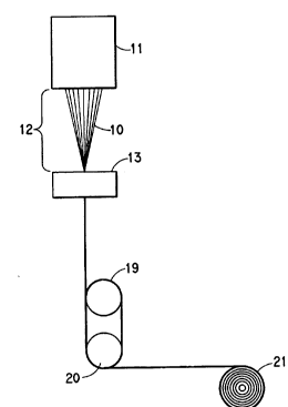
Referring to Figure 1, polyamide filaments 10 are
extruded from a spinneret 11 through a gas-filled
(preferably air) gap 12 and into a quench bath 13
containing an aqueous liquid. As shown in Figure 2, a
nozzle 14, situated below the surface of the bath, defines
a cylindrical passage 15 disposed in a generally vertical
position with entrance 16 opening into the bath and exit
17 at the other end of the passageway outside the bath.
Cylindrical passage 15 should have a cross-sectional area
sufficient to accommodate the filament bundle and
entrained bath liquid but it should not be so great as to
allow excessive loss of bath liquid. Supplementary
aqueous quench liquid, preferably water, is fed into the
quench bath through inlet means not shown to make up for
loss through the exit nozzle. Filaments 10 are converged
into a filament bundle at entrance 16 of passageway 15,
and leave at exit 17 together with entrained bath liquid.
Referring back to Figure 1, the filaments are withdrawn
from quench bath 13 and are wrapped around feed rolls 19
and 20 before being wound up on wind-up roll 21.
2t~7378
~09StO2718 3 PCT~S94/07589
Spinning conditions, as will be understood by
those skilled in the art, should be selected to minimi~e
periodic denier variations in the fibers and/or fiber
breakage. This may be caused by improperly coordinated
jet velocity, polymer temperature, relative viscosity and
size of the gas-filled gap and draw-down ratio. The draw-
down ratio as used herein is defined as the ratio of the
speed of filament bundle withdrawal from the exit of the
nozzle passageway (measured as the surface speed of the
feed rolls), to the jet velocity of the polymer through
the spinneret capillaries. Jet velocity is readily
calculated by dividing the total volume of polymer passing
through the spinneret (cc/min) as determined by the pump
speed, by the total cross-sectional area (cm2) of the
spinneret orifices.
The filament bundle is withdrawn from the exit of
the nozzle passageway at a speed preferably between about
1500 to about 3500 m/min. Withdrawal speed also referred
to herein as spinning or feed roll speed, of less than
about lS00 m/min. results in yarn that is inadequately
drawn and has undesirably high elongation. Withdrawal
speeds of greater than about 3500 m/min. result in over-
drawn yarn having undesirably low elongation and
toughness. Generally, elongations of less than about 70%
in bulked continuous filament yarns suitable for carpet
yarn and less than about 40% in textile yarns are
desirable. Either or both the jet velocity and the
withdrawal speed should be adjusted so that the draw-down
ratio falls between about 10 and 50.
The relative viscosity (RV) of the polyamide to be
spun is preferably between about 45-S0. Below about 40 RV
the operable window narrows and at much above 50 RV, pack
pressure can become a problem.
The gas-filled gap is preferably an air gap,
however, steam may also be used. The length of the gas-
filled gap should be set to give fiber of the desired
physical properties. Preferably, the gap length is
between about 5 cm to about 20 cm. Threadline tension
WO95/02718 2 1 6~ 7 3 7 ~ PCT~S94/07589
decreases with increasing gap length and this sets upper
and lower bounds on operable gap lengths. For example,
when spinning 19 dpf (21 dtex/filament) 6,6 nylon yarns at
2000 ypm (1830 m/min) from a spinneret with capillaries
placed on three concentric circles with 2.1, 1.8, and 1.5
in (5.3, 4.6, and 3.8 cm, respectively) diameter, the
longest operable gap lengths were about 20 cm. At about
25 cm, the threadline tension was too low, and the
filaments started to touch each other and stick together.
During string-up, the quench bath was raised to within
about four inches of the spinneret to break the bundle
apart. Once the bundle was opened, the filaments remained
separate as long as the gap length was kept at 20 cm or
less.
It is important that the filaments be solidified
before the threadline converges. If two filaments have
touched and are stuck together, as during string-up, they
should be separated. However, once they are separated,
only enough force to keep them from wandering about is
required to keep them separated. Experiments with
different quench bath geometries have shown that the
filaments solidify at about 2.5 cm or more beneath the
surface of the quench bath.
Although quantitative measurements of thread-line
tension in the gap were not made, the increase in tension
as the gap length is decreased is visually apparent. At
large gap lengths, tension is lost completely and the
filaments fall straight down into the quench bath. As the
gap length decreases, enough tension is developed to cause
the filaments to converge at the entrance to the nozzle in
the quench bath. The preferred situation is to have just
enough tension for this to happen. At this point, the
attenuation of the filaments above the quench bath is only
modest. Further decreases in gap length lead to further
increases in tension and to marked attenuation of the
filaments above the quench bath. Visual observation
reveals that at very small gap lengths most of the
attenuation occurs above the quench bath.
21 67378
~O95/02718 PCT~S94/07589
Generally, the largest operable gap lengths are
preferred because they yield the best physical properties.
As the gap length decreases, both tenacity and elongation
decrease. Usually, there is little loss of tenacity until
the gap length drops below about 15 cm. The preferred gap
length varies with the filament denier. In general, gap
lengths of about 5 to about 20 cm are preferred. For
continuous filament yarns (dpf of about 15-2S; 17-28
dtex/filament), gap lengths of 10-15 cm offer the best
balance of process stability and physical properties.
With textile yarns (dpf of about 1.5-6; 1.7-6.7
dtex/filament), loss of tension occurs at smaller gap
lengths, i.e., about 10 cm, and the preferred operating
range is 5-8 cm.
The aqueous quench liquid is preferably water.
Addition of a finish composition to the quench bath
obviates the need for applying a finish later in the
process, and is desirable to prevent yarn damage during
processing. In general, dilute finish compositions
improve operability considerably. Hydrophilic finish
compositions containing ethoxylated components are
suitable for use in the current process. Surfactants in
conjunction with an antifoaming agent were also found to
give excellent results. Other additives such as dyes,
reserving agents, antisoil compositions or the like may
also be added to the quench bath.
The temperature of the quench bath is an important
variable. Temperatures of from about 45C to a
temperature less than the boiling point of the aqueous
quench liquid give acceptable fiber properties. Yarns
quenched in 25C water had poor physical properties
(tenacity <1.0 gpd t0.88 dN/tex)). Increasing the
temperature of the quench bath resulted in significantly
improved physical properties. Temperatures of about 85 to
95C are preferred, especially if yarns having high dye
rates are desired. It is important that the bath
temperature be maintained approximately constant to obtain
yarns having uniform properties.
WO95/02718 2 1 6 7 3 7 8 PCT~S94/07589
The depth of the quench bath, that is, the
distance from the entrance 16 of the nozzle passageway to
the surface of the quench bath, is preferably about 2 to
about 5 cm. Reducing the depth of the quench bath
improves tenacity and elongation slightly, but reduces
filament spacing at the bath surface, thus making it more
difficult to keep the filaments from sticking together.
There is no need to increase the bath depth beyond that
which is necessary to keep the filaments from sticking to
each other. The tension on the filaments increases with
increasing bath depth, resulting in reduced filament
properties.
The vertically-mounted nozzle situated at the
bottom of the quench bath or at least beneath the surface
of the bath provides a passageway through which the
threadline exits from the quench bath. The nozzle
passageway is preferably cylindrical and smooth to develop
a favorable flow pattern. A non-round passageway causes
irregular flow patterns which leads to stuck filaments.
The entrance to the nozzle passageway is preferably
rounded off to prevent abrasion damage to the filaments.
The exit preferably is a knife edge with the nozzle wall
cut back at about a 45 degree angle so the quench fluid
traveling with the threadline separates cleanly from the
nozzle. A stripper jet may be used after the quench bath
to reduce the water content of the threadline before
winding up the yarn.
The diameter of the nozzle passageway and the
depth of the quench bath are preferably such that the
tension on the filament bundle exiting the nozzle and as
measured at the feed rolls is between about 2 and about 6
g/filament. If the diameter is too large, too much water
travels with the threadline. Since the water is
eventually accelerated to the withdrawal speed, the
threadline tension becomes excessive and the yarn is over-
drawn and may be broken. On the other hand, if the
diameter is too small, the threadline is choked off and
the device cannot be strung up. For yarns having a bundle
2t 6737~
~095/02718 PCT~S94/07589
denier of about 1440 dtex, a passageway diameter of about
5/32 inch (4.0 mm) is preferred. For textile yarns having
a bundle denier of about 40 (44 dtex), a 1/16 inch (1.6
mm) diameter is useful.
The length of the nozzle passageway is not as
important as its diameter. Lengths as short as 1/8 inch
(3 mm) and as long as 6 inches (15 cm) gave acceptable
results. Very short lengths give somewhat inferior yarns
and very long nozzles are awkward to handle.
TEST METHODS
In the examples, the stated denier values are
nominal deniers. Physical properties were measured on
relaxed yarns whose denier were a few percent higher.
Yarn uniformity was determined with the use of a
capacitance-type evenness tester. This apparatus gives a
measure of the evenness of the yarn in terms of the
percent coeffic~ent of variation, CV, which is equivalent
to 100 times the standard deviation of successive denier
determinations divided by the mean. Values reported
herein were determined on a Uster evenness tester, Model
B, equipped with a quadratic integrator, using the
manufacturer's procedure for the measurement. The higher
the value of CV, the poorer the yarn evenness. Two
measurements are made, corresponding to very short range
evenness (corresponding to 0.076 cm or 0.03 inch cut
length) and long range evenness (corresponding to S49 cm
or 216 inch cut length).
Polymer RV was measured according to the procedure
described in U.S. 3,511,815. Yarn tenacity, or normalized
breaking load, elongation and modulus were determined by
ASTM Method D-2256-80, using a tensile testing machine
meeting the standards of the method (Instron Model 1122,
Instron Engineering Corp., Canton, Mass.). Pneumatic
action snub-nosed grips were used. Tests were run at 60%
elongation/minute. Tenacity values reported herein were
determined using samples having a gage length of 10 inches
and a twist of 3 turns/inch. The yarns were conditioned
WO95/02718 2 1 6 ~& PCT~S94107589
at 65% relative humidity and 70 degrees C prior to
testing.
EXAMPLE I
43.6 RV nylon 6,6 was spun through an air gap into
a quench bath to produce 133 denier 19 dpf (21
dtex/filament) yarns using a process as illustrated in
Figure 1.
A spinneret with 7 trilobal capillaries in about a
25.4 mm circular arrangement was used. The capillaries
had a cross-sectional shape which can be described as
three slots with semi-circular ends with the width of the
slots being 102 ~m, the length of the straight section
being 152 ~m, and the total cross-sectional length was 203
~m. The capillary length was 127 ~m. A long
countersink, 40 degree included angle, 1.27 mm long, was
provided as a precaution against melt fracture. The
cross-sectional area of each capillary is 0.0588 mm2.
The nozzle associated with the quench bath defined
a passageway that was 3.2 mm in diameter and 25 mm long.
The depth of the bath above the entrance to the nozzle
passageway was 13 mm. The quench liquid was water at a
temperature 90C. The distance from the spinneret to the
surface of the water (the gap) was 152 mm. An interlace
jet operating at an air pressure of 50 psig was used to
reduce the water content of the threadline exiting the
quench bath.
Items A-D were made at the speeds described in
Table 1. The draw-down was 31.7 for all items.
'~0 95/02718 2 ~ 6~ 7 ~ PCT/US94/07589
OD U~ ~ ~
C-, 1 . . ~
o ~r ,1 ,~
-
x ~
0 ~ o o o o
S
, c a~
0 0
E~ ~ O O O o
tr
a) . . .
~5 co a~ ~ co
O
~ t~ u
t
&a ~ . . .
p ~ t~ ~ ~ o
O ~ In t~ CD O
O--
D ' ~ O
CO ~ O
0 ~
01
H¦ '¢ r~ U ~
wo gS/02718 2 1 6 ~ 10 PCT~S94/07589
Each set of physical properties of the yarns
represents the average of three measurements. The gradual
loss of tenacity, elongation, and toughness with
increasing speed is evident. The high Uster value of item
B is unexplained.
EXAMPLE II
The same spinneret was used to spin 50 RV nylon
6,6 into 133 denier, 19 dpf, at a constant 1829 m/min
spinning speed, but with varying air gaps. The quench
bath temperature was about 85C. Items A-E were made
using the air gaps indicated in Table 2.
TABLE 2
Item Air gap T E CV
mm g/den (dN/dtex) _~O
A 203 2.81 (2.48) 51 3.15
B 152 2.49 (2.20) 46 3.05
C 102 2.43 (2-14) 50 1.75
D 51 2.01 (1.77) 43 2.19
E 25 1.64 (1.45) 41 2.83
There is gradual loss of physical properties as
the air gap gets smaller. Uniformity is best at inter-
mediate air gaps where there is some, but not too much,
tension.
EXAMPLE III
Using the same spinneret and the same polymer as
in Example II, a series of yarn with varying dpf (and
corresponding denier) were spun using a spinning speed of
1829 m/min and an 152 mm air gap. Items A-D were made
with the dpf indicated in Table 3.
WO95/02718 2 t ~ 7~ ~ PCT~S94/07589
TABLE 3
Item ~E~ T E CV
q/den (dN/dtex) % %
A 19 2.49 (2.20) 46 3.05
B 34 2.19 (1.93) 53 1.85
C 55 1.75 (1.54) 61 2.11
D 80 1.18 (1-04) 57 1.99
Item A with a draw-down of 31.7 still has a trace
of draw resonance which explains the higher CV. The other
three items all have lower draw-down (by the ratio of
their dpf to 19) and show no signs of draw resonance.
EXAMPLE IV
(Comparative Example)
Item C of Example II was repeated with a different
spinneret. The width of the slots was 254 ~m. The length
of the straight portion was 371 ~m. The total length of
the slots was 498 ~m. The area of the capillary was 0.36
mm2. The computed jet velocity was 9.4 m/min. The draw-
down was 195. This item had 3.95 % CV and showed a
pronounced draw resonance with a wave length of about
10 m. The use of smaller capillaries could avoid draw
resonance.
EXAMPLE V
A textile yarn with a nominal denier of 123 was
spun using a process and apparatus as illustrated in
Figure 1.
The spinneret had 34 holes on two concentric
circles with 25 and 33 mm diameter. The capillaries had a
circular cross-section and were 89 ~m in diameter and
279 ~m long. The jet velocity was 104 m/min and the draw-
down 17.6. The quench water temperature was 85C and theair gap was 7.6 cm. The feed roll speed was 1829 m/min.
The resulting relaxed yarns were 134 denier and
had 3.53 gpd tenacity, 55% elongation, 23.4 gpd modulus,
W095/02718 2 1 6 7 3 7 8 12 PCT~S94/07589
and 1.30 gpd toughness. Re-testing gave 3.74/62/21.9/1.54
and 3.56/60/22.3/1.48. Uster CV was 5.2 %.
Feed roll speed was increased to 2286 m/min
without changing pump speed. This decreased nominal
denier to 98, and increased draw-down to 22Ø Relaxed
yarns were 108 denier and had 3.42 gpd tenacity, 40%
elongation 24.4 gpd modulus, and 0.91 gpd toughness.
Re-testing gave 3.90/47/24.2/1.22 and 3.72/44/23.4/1.07.
Uster CV was 1.5 % with no evidence of draw resonance.
Feed rvll speed was further increased to 2743
m/min without changing pump speed. This decreased nominal
denier to 82, and increased draw-down to 26.4. Relaxed
yarns were 91 denier and had 3.67 gpd tenacity, 32%
elongation 23.4 gpd modulus, and 0.77 gpd toughness.
Re-testing gave 3.86/35/25.1/0.89 and 3.83/37/26.6/0.97.
Uster CV was 1.6 %.