Note: Descriptions are shown in the official language in which they were submitted.
- zis74sz
CONTROL AND ARRANGEMENT OF A CONTINUOUS PROCESS FOR,AN
INDUSTRIAL DRYER
BACKGROUND OF THE INVENTION
The present invention relates to web supporting and drying
apparatus. In drying a moving web of material, such as paper,
film or other sheet material, it is often desirable that the web
be contactlessly supported during the drying operation, in order
to avoid damage to the web itself or to any ink or coating on the
web surface. A conventional arrangement for contactlessly
supporting and drying a moving web includes upper and lower sets
of air bars extending along a substantially horizontal stretch
of the web. Heated air issuing from the air bars floatingly
supports the web and expedites web drying. The air bar array is
typically inside a dryer housing which can be maintained at a
slightly sub-atmospheric pressure by an exhaust blower that draws
off the volatiles emanating from the web as a result of the
drying of the ink thereon, for example. The exhausted gases can
then be treated to oxidize any volatile components, and the
resulting clean gases can then be released to atmosphere.
Temperatures sufficient to fully oxidize the volatiles
(typically in the 1250°F to 1500°F (675°C - 815°C)
range) are not
reached in dryers of this type. Nor is sufficient residence time
or mixing provided to cleanly treat the volatiles, for example.
Indeed, it is desirable to avoid, or mitigate to the greatest
extent possible, the partial oxidation and cracking of the
volatiles, as partially oxidized and cracked compounds are often
more deleterious than volatile material which has undergone
little or no decomposition. The former may result from
incomplete combustion due to insufficient oxygen, arrested
1
216?462
combustion or insufficient temperature and length of time,for the
reaction to be completed, resulting in the generation of soot,
carbon black, aldehydes, organic acids and carbon monoxide. The
condensation and formation of the solids of these unwanted
compounds on the internal surfaces of the drying apparatus are
undesirable, as high accumulations may contaminate the web and
product, may eventually adversely affect the operation of the
dryer, and may present a fire hazard.
Additionally, it is desirable to provide make-up air to the
dryer in such a way that internal surfaces are not unduly cooled,
thus causing sites for the formation of condensation and solids
of incomplete combustion.
It is theref ore an object of the present invention to
mitigate condensation and sapping of solvent and solvent-based
by-products in an industrial dryer.
It is a further object of the present invention to provide
for more thorough mixing of dryer atmosphere in order to maintain
even solvent concentrations throughout the dryer enclosure.
SUMMARY OF THE INVENTION
The problems of the prior art have been overcome by the
present invention, which provides staged (indirect) heating of
solvent laden air recirculating within a drying enclosure, and
a method of optimally controlling and directing solvent laden
recirculation air such that condensation and sapping of solvent
and various solvent-based by-products may be effectively reduced
or eliminated. In addition to the reduction of condensate, a
greater and more uniform mixing of the atmosphere within the
2
CA 02167462 2005-11-15
76407-14
drying enclosure is achieved, thereby enhancing safety and
the drying process as pockets of high concentration solvent
vapors are reduced.
In one aspect of the present invention, there is
provided an apparatus for drying a travelling web of
material having a coating containing volatile substances,
comprising: a dryer enclosure having a web inlet opening and
a web exit opening spaced from said web inlet opening, said
dryer enclosure including at least a first drying zone
having a first drying zone atmosphere and a leaving drying
zone having a leaving drying zone atmosphere; a plurality of
air jet nozzles in each of said drying zones for blowing air
onto said web; a burner in said dryer enclosure, said burner
being in communication with air from outside said dryer
enclosure; and recirculation means in communication with
said burner for recirculating a mixture of leaving drying
zone atmosphere and said air from outside said dryer
enclosure to said first zone of said dryer while the web is
travelling.
In a second aspect of the present invention, there
is provided an apparatus for drying a travelling web c>f
material having a coating containing volatile substances,
comprising: a dryer enclosure having a web inlet opening and
a web exit opening spaced from said web inlet opening, said
dryer enclosure including at least a first drying zone
having a first drying zone atmosphere and a leaving drying
zone having a leaving drying zone atmosphere; a plurality of
air jet nozzles in each of said drying zones for blowing air
onto said web; a burner in said dryer enclosure for
oxidizing volatiles in said leaving drying zone atmosphere;
recirculation means in communication with said burner for
recirculating a mixture of oxidized leaving drying zone
atmosphere, unoxidized leaving zone dryer atmosphere and air
3
CA 02167462 2005-11-15
76407-14
from outside said dryer enclosure to said first zone of said
dryer while the web is travelling.
In a third aspect of the present invention, there
is provided a method of drying a coated travelling web in a
dryer enclosure having at least a first drying zone and a
leaving drying zone, comprising: floatingly passing s<~id web
through said dryer enclosure while heating said web;
introducing air from outside said dryer enclosure into said
dryer enclosure; heating said air from outside said dryer
enclosure; mixing said heated air from outside said dryer
enclosure with a portion of solvent laden air from said
leaving drying zone; and recirculating said mixture of air
into said first drying zone while the web is travelling.
BRIEF DESCRIPTION OF THE DRAWINGS
Figure 1 is a schematic representation of a dryer
having staged (indirect) heating in accordance with the
present invention;
Figure 2 is a schematic representation of a dryer
having staged (indirect) heating in accordance with an
alternative embodiment of the present invention;
Figure 3 is a schematic representation of the
dryer of Figure l, with the addition of a fully integrated
conditioning zone; and
Figure 4 is a schematic representation of a dryer
including an integrated oxidizer in accordance with a
further embodiment of the present invention.
DETAILED DESCRIPTION OF THE INVENTION
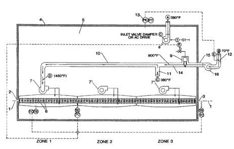
Turning now to Figure 1, an embodiment of the
drying process in accordance with the present invention has
3a
CA 02167462 2005-11-15
76407-14
an enclosure 4 of gas- tight construction, the enclosure 4
having an inlet slot 2 and an exit slot 3 spaced from said
inlet slot 2, through which a moving, continuous web of
material 1 enters and exits respectively. Said web of
material 1 is floatingly supported continuously through the
dryer by a series of upper and lower air jet nozzles 6. For
optimum heat transfer characteristics, the jet nozzles 6
preferably include Coanda-type flotation nozzles
3b
zis74sz
such as the HI-FLOAT' air bar commercially available from W.R.
Grace & Co.-Conn., as well as direct impingement nozzles such as
hole bars. Preferably each direct impingement nozzle is
positioned opposite a Coanda-type air flotation nozzle. The air
jet nozzles 6 are provided with high pressure gas through a
direct connection to supply fans 7, 7' and 7". It is important
to note that dryers of this type and duty are often considered
to be comprised of zones which are, in turn, demarcated by the
influence of one or more supply fans . And as such, the intensity
of the drying of the web of material is directly related to the
magnitude of the temperature and velocity of the gas emitted by
the jet nozzles directly connected to supply fans, and thus the
real drying rate may vary from zone to zone. In accordance with
the present invention, there may exist from one to any plurality
of zones with no need for physical walls or barriers to separate
the zones. Figure 1, as an example, has three zones: a first
zone (zone 1), a middle zone (zone 2) and a leaving zone (zone
3) .
As the web of material 1 travels through the dryer 4, the
volatile components of the coating on the web 1, such as solvents
from ink, evaporate and are absorbed into the internal dryer
atmosphere 5. To prevent dangerous concentrations of solvent
vapor from accumulating within the enclosure 4, an exhaust fan
8 is employed to extract internal gases at a rate sufficient to
maintain acceptably safe concentrations of volatile vapors. To
make up for the gases extracted, atmospheric air (at
approximately 70°F) free of all volatile material is allowed into
the dryer enclosure 4 through make-up air opening 15. The mass
4
2167462
flow rate of clean air allowed into the enclosure 4 is controlled
via a pressure sensing device 13 which monitors and controls the
static pressure within the dryer enclosure 4 to an operator
determined set point. A slight negative static gauge pressure, -
0.25 mbar to -1.25 mbar for example, is maintained within the
enclosure 4 to minimize or prevent vapors from escaping through
inlet slot opening 2 and outlet slot opening 3. The pressure
sensing device 13, through a controller, manipulates, for
example, a make-up air damper 12 which controls the amount of air
that enters the enclosure 4 through opening 15. Alternatively,
a variable speed fan could be used instead of the damper 12 to
perform this function. Figure 1 also includes, for example, a
make-up air fan 16 which draws fresh air through the make-up
damper 12 and pushes the air into the enclosure 4 and into burner
tube 14. The burner tube 14 houses the burner 9, which in this
embodiment is preferably a raw gas type burner. Sufficient air
supply (secondary air) is forced around and through flame front
to support combustion. The burner tube 14 is sealed air-tight
to make-up air damper 12 and the ambient surroundings and thus
only clean air is allowed to pass through the burner tube 14 and
have contact with burner flames; solvent laden air is not exposed
to the burner or burner flame. The resulting heated, clean make-
up air exits the burner tube 14 at a temperature of about 800°F
and is mixed with solvent laden dryer atmosphere air (having.a
temperature of about 380°F) in mixing channel 10. Dryer
atmosphere air enters the mixing channel 10 via the recirculation
duct 11.
In this way, volatiles in the form of vapors that are
2167462
present in the dryer enclosure 4 never have direct conbact with
the burner 9 or burner flame. This greatly reduces the formation
of intermediate compounds that are created by partial oxidation
and which may condense in various forms on cool surfaces within
the dryer enclosure 4. Also, because the clean make-up air,
which is at an ambient temperature of usually 68°-85°F., is
heated immediately without contact with internal surfaces or
volatiles, the incidence of condensation in the dryer enclosure
is significantly reduced. The mixing channel 10 is under
negative gauge pressure since it is ducted air-tight to the inlet
side of supply fan 7. The heated air mixture exiting the mixing
channel 10 (having a temperature of about 450°F) is then
distributed by supply fan 7 through the jet nozzles 6 of this
zone.
The air mixture mass flow rate requirement D of the supply
fan 7, connected to the mixing channel 10, must be greater than
the clean air mass flow rate B that is required as make-up air.
If the enclosure 4 is gas-tight and air infiltration thorough the
inlet and outlet slot openings 2, 3 is considered to be
negligible, then the make-up air rate B is essentially equal to
the exhaust rate A. The mass flow rate requirement D is then
equal to the combined mass flow rates of fresh make-up air B and
dryer atmosphere air C. The flow pattern within the dryer
enclosure 4 is thus established: a controlled mass flow rate of
solvent laden air A is exhausted from the leaving end or last
zone of a heating dryer. An equal amount of fresh make-up air
B enters the enclosure and is heated by a burner 9 and is
separately mixed with dryer atmosphere air C which is also
6
2167462
extracted from the leaving end or last zone of the dryer. The
heated fresh air and solvent laden dryer atmosphere is then
transported to the entering end or first zone of the heating
dryer. The air mixture is then discharged through the jet
nozzles 6 of this zone and impinges directly on the web of
material 1. This mixture of air is evenly distributed throughout
zone 1. Since there is no provision made for recirculation of
this air mixture directly back to the supply fan 7 of zone 1, all
of the air discharged from the jet nozzles of this zone must
cascade or traverse into the next zone ( zone 2 ) . The air mixture
from zone 1 then is mixed with air that is discharged from the
jet nozzles of zone 2. A portion of this mixture is recirculated
into the supply fan 7' of zone 2 while the balance is cascaded
to the next zone (zone 3). Because the exhaust fan 8 and the
recirculation duct 11 are in the last zone of the dryer, a mass
flow rate of air equal to D cascades through the entire dryer.
Additionally, all clean air that is introduced to dryer
atmosphere 5 is available immediately at the entering end (zone
1) of the dryer and then throughout the entire dryer as it
cascades toward the leaving end or last zone.
In typical operation, the web of material 1 coated with
volatile containing materials is heated to volatilization of
these materials in zone 1 with only a small amount of volatiles
being released. As the web of material 1 travels further into
the dryer, volatiles are evaporated at an increasing rate. Thus,
it can be expected that the greatest concentration of volatile
vapors may accumulate in the latter zones of a dryer or in the
zone to which the exhaust fan may draw them. Since a high
7
2167462
concentration of volatile vapors may present an unsafe cpndition
and impede the drying phenomenon due to high vapor pressures in
the convection air currents, it is advantageous to prevent areas
of high concentrations from forming. As it is expected that high
concentrations may accumulate in the leaving end of the dryer,
a portion of this air mixture is extracted via recirculation duct
11, mixed with clean air, and then distributed in the first zone
where volatile concentrations are typically the lowest.
Therefore, the combined redistribution of high concentration
air from the last zone to the first, together with the cascade
effect of all available clean air through the dryer, provides for
a more safe environment within the dryer enclosure 4. Moreover,
the staged (indirect) heating of the dryer atmosphere by heating
clean make-up air greatly reduces the likelihood of volatiles
condensation, since no volatile vapors contact the cool make-up
air or any surfaces that may be cooled by the clean make-up air
entering the dryer enclosure 4 at ambient temperatures.
Figure 2 depicts an alternative embodiment of the present
invention, wherein fan 16 of Figure 1 is eliminated. Burner 9'
is preferably a nozzle mix type burner, receiving clean, ambient
combustion air (primary air) via a combustion blower 100 at a
nearly constant rate. The combustion air mixes with burner fuel
through the burner nozzle just prior to combustion. Damper 12'
controls the mass flow rate of clean, ambient make-up air
(secondary air) flowing to burner 9'. Both the primary air from
the combustion blower and the secondary air (supplied through
damper 12') are together considered make-up air. However, the
control is separate in that the primary air supplied by the
8
2167462
combustion blower 100 is controlled according to the firing rate
of the burner, whereas the secondary air is controlled via the
make-up air damper 12', which in turn is controlled by the
pressure sensor/controller 13 which controls the pressure in the
dryer enclosure. The remainder of the flow patterns within the
dryer are the same as with the embodiment of Figure 1.
Turning now to Figure 3, there is shown a dryer similar to
the dryer of Figure 1, with the addition of a conditioning zone
50 fully integrated therewith. The web 1 enters the conditioning
zone enclosure 50 via a conditioning zone enclosure opening 51.
The web 1 is supported in the zone 50 by a series of additional
air jet nozzles 52, preferably a combination of Coanda-type air
bars and direct impingement nozzles oppositely opposed, and
finally exits the conditioning zone 50 via opening 53.
Preferably the conditioning zone enclosure 50 is contained and
fully integrated within the dryer enclosure 4, and is maintained
gas tight and thermally insulated from the dryer enclosure 4 via
an insulated wall 54. A pair of opposed gas seal nozzles can be
positioned on both sides of the entering end opening 51 in the
insulated wall 54 of the conditioning zone 50. Although any type
of air nozzle that can effectively direct air so as to prevent
unwanted gas flow through the opening 51 can be used as the gas
seal nozzles, preferably the gas seal nozzles on the dryer side
are conventional air knives capable of delivering air at a
velocity of from about 6000 to about 8500 feet per minute, and
preferably the gas seal nozzles on the conditioning zone side are
conventional air foils capable of delivering air at a velocity
of about 1000 to about 4500 feet per minute, both commercially
9
2167462
available from W. R. Grace & Co.-Conn. The dryer side gas seal
nozzles force dryer atmosphere air counter to the direction of
travel of the strip of material 1, and the conditioning zone side
gas seal nozzles force conditioning zone atmosphere air counter
to the direction of travel of the strip of material 1. The pair
of opposing gas seal, nozzles are sealed to the conditioning zone
insulated wall 54 with gasket seals, such that any differential
pressure that may exist from the dryer enclosure 4 atmosphere to
the conditioning zone 50 atmosphere will not cause an unwanted
flow of gases through the opening 51. This gas seal arrangement
is especially important in preventing solvent vapors from
entering the conditioning zone 50 from the dryer 4 through
opening 51. Specifically, the control and prevention of unwanted
gas flow through the opening 51 is achieved by the directionality
of the air jets of the gas seal nozzles. The air knives produce
a very distinct, high velocity, high mass flow discharge of gas
in a direction counter to the direction of travel of the strip
of material 1, and thus cause a bulk movement of dryer atmosphere
air away from the opening 51 and the conditioning zone enclosure
50. This constitutes a major portion of the sealing against
flows due to possible differential pressure states and/or
discharges from the adj oining j et nozzles . To further reduce the
flow of solvent vapors into the conditioning zone enclosure,
conditioning zone side gas seal nozzles produce a discharge of
relatively clean air, as is controlled within the conditioning
zone enclosure S0, and again, in a direction counter to the
direction of travel of the strip of material 1. This clean air
discharge has a low solvent vapor pressure and thus readily mixes
2167462
with the thermal boundary layer of air on the surface,of the
strip of material 1, which is of relatively high solvent vapor
pressure. The counter flow of this mixture effectively scrubs
solvent vapors from the strip of material, preventing entrance
to the conditioning enclosure 50 by way of induced flow in the
opposite direction into the dryer enclosure 4.
Since the air that is drawn into the conditioning zone 50
is relatively cool ambient air, and since this air is directly
discharged onto the strip of material 1 via the air jets in the
conditioning zone 50, the hot strip of material 1 is cooled. The
heat from the strip of material 1 is absorbed by the discharged
air and is drawn out of the conditioning zone 50 via duct 150
having damper 12' and into the burner 9.
In order to further control and prevent solvent condensation
within the conditioning zone enclosure, a heat gas seal (not
shown) may be provided just prior to the exit end opening 53.
Any suitable nozzles can be used to provide the thermal gas seal,
as long as they fulfill the requirement of providing an even, low
velocity discharge of hot air into the cold air stream flow that
enters the enclosure as infiltration air through exit end opening
53. The discharge velocity of the thermal gas seal nozzles is
from about 0 to about 6000 feet per minute, depending upon
temperature requirements. The nozzles are mechanically sealed
to the conditioning zone exit wall using suitable gaskets. Hot
air provided to this gas seal is controlled via a gas seal
damper. The hot air from this gas seal is free of solvent vapors
and provides temperature control of the atmosphere within the
conditioning zone 50. Hot air expelled from the gas seal is
11
2167462
directed into the conditioning zone enclosure 50 inter~.or and
mixes with cold ambient air that enters the exit end opening 53
as infiltration air, thus heating the infiltration air and, upon
mixing with enclosure atmosphere, raising the average air
temperature throughout the conditioning zone enclosure 50. A
higher air temperature allows for more vapor to be absorbed,
thereby reducing the likelihood of condensation. In this way,
the operator of the equipment can strike an optimal balance
between providing cooling air for cooling the web, and adding
just enough heat to prevent condensation from forming.
Alternatively, a heater such as electric heater 140 can be
provided to heat any infiltration air that may enter the
conditioning zone 50 through the web exit slot 53. The heater
140 can also control the air temperature in the conditioning zone
50.
Turning now to Figure 4, there is shown a dryer including
an integrated oxidizer and a conditioning zone 50'. Exhaust air
is drawn from the leaving end or last zone of the heating dryer
via a fan 100. This exhaust air is pre-heated by a heat
exchanger 101, and is then heated to oxidation temperature
(approximately 1400°F) by one or more burners 102. The heated
air, now at a temperature sufficient to fully oxidize the
volatiles to innocuous products and thus clean air, enters a
combustion chamber 107 for further mixing and for a sufficient
time to complete the reaction. A small portion of the resulting
hot, clean air leaves the chamber 107 through duct 103 and is
mixed with a combination of conditioning zone 50' air (at
approximately 200°F) from duct 104 and dryer atmosphere air (at
12
2167462
approximately 380°F) from duct 105. The resulting gas~mixture
having a temperature of approximately 450°F is transported to the
first, or entering zone 1 via mixing duct 108. The remaining
hot, clean air is passed through the heat exchanger 101, where
it pre-heats exhaust gases, and is vented to atmosphere through
duct 106.
The control of the make-up air through duct 104 and dryer
atmosphere air through duct 105 may be accomplished by a damper
109, which, for example, controls both flows simultaneously
either interconnectedly or by separate controls. Thus, when the
damper part of duct 104 opens to allow more flow, the damper past
of duct 105 closes to equally decrease the mass flow rate through
duct 105. Additionally, a fan may be connected directly to duct
104 which in concert with a make-up air damper on the inlet side
of the fan, or in concert with a variable speed drive, may draw
air from conditioning zone 50' and force it controllably into the
heating dryer. The flow patterns within the dryer are then
identical to those for the dryer of the first embodiment
discussed above.
13