Note: Descriptions are shown in the official language in which they were submitted.
9 1 1
W096/00034 PCT~S95/07954
ELECTRO~YTICA~LY SEVE ~3LE COI~ ASSEMB~Y WITH MOVAB~E
DETACHMENT POINT
Field of the Invention
This invention is an apparatus for creating an
endovascular occlusion by the formation of thrombi in
such vascular locations as arteries, veins, aneurysms,
vascular malformations, and arteriovenous fistulas. In
particular, the invention is an assembly for
electrolytically severing a portion of the endovascular
device such as a coil via the use of electrolysis. The
vasoocclusive device is introduced through a catheter and
is intended to remain at the desired thrombus formation
site. The invention further includes a method for the
introduction of the device and its electrolytic
separation.
Backqround of the Invention
Approximately 25,000 intracranial aneurysms
rupture each year in North America. The primary purpose
of treatment for a ruptured intracranial aneurysm is to
prevent re-bleeding. There are a variety of ways to
treat ruptured and non-ruptured aneurysms.
Possibly the most widely known of these
procedures is an extravascular approach using surgery or
microsurgery. This treatment is common with intracranial
berry aneurysms. The method comprises a step of clipping
the neck of the aneurysm, performing a suture ligation of
the neck, or wrapping the entire aneurysm. Each of these
procedures is formed by intrusive invasion into the body
_ ~ ~ ~
W096/00034 7 ~1 ~ . PCT~S95/07951
and performed from the outside of the aneurysm or target
site. General anesthesia, craniotomy, brain retraction,
and placement of a clip around the neck of the aneurysm
are typically required in these surgical procedures. The
surgical procedure is often delayed while waiting for the
patient to stabilize medically. For this reason, many
patients die from the underlying disease or defect prior
to the initiation of the procedure.
Another procedure -- the extra-intravascular
approach -- involves surgically exposing or stereotaxicly
reaching an aneurysm with a probe. The wall of the
aneurysm is then perforated from the outside and various
techniques are used to occlude the interior in order to
prevent it from re-bleeding. The techniques used to
occlude the aneurysm include electrothrombosis, adhesive
embolization, hog hair embolization, and ferromagnetic
thrombosis. These procedures are discussed in U.S.
Patent No. 5,122,136 to Guglielmi et al., the entirety of
which is incorporated by notice.
A still further approach is the least invasive
and is additionally described in Guglielmi et al. It is
the endovascular approach. In this approach, the
interior of the aneurysm is entered by use of a catheter
such as those shown in Engelson (Catheter Guidewire),
U.S. Patent No. 4,884,575 and also in Engelson (Catheter
for Guidewire Tracking), U.S. Patent No. 4,739,768.
These patents describe devices utilizing guidewires and
catheters which allow access to the aneurysm from remote
portions of the body. Specifically, by the use of
catheters having very flexible distal regions and
guidewires which are steerable to the region of the
aneurysm, embolic devices which may be delivered through
the catheter are an alternative to the extravascular and
extra-intravascular approaches.
~ Wo96/OQO34 ~ 1 6 7 9 11 PCT~Sg5/07954
The endovascular approach typically includes
two major steps. The first step involves the
introduction of the catheter to the aneurysm site using
devices such as shown in the Engelson patents. The
second step often involves filling the aneurysm in some
fashion or another. For instance, a balloon may be
introduced into the aneurysm from the distal portion of
the catheter where it is inflated, detached, and left to
occlude the aneurysm. In this way, the parent artery is
preserved. Balloons are becoming less in favor because
of the difficulty in introducing the balloon into the
aneurysm sac, the possibility of an aneurysm rupture due
to overinflation of the balloon within the aneurysm, and
the risk associated with the traction produced when
detaching the balloon.
A highly desirable embolism-forming device
which may be introduced into an aneurysm using
endovascular placement procedures, is found in U.S.
Patent No. 4,994,069, to Ritchart et al. There is
described a device -- typically a platinum/tungsten alloy
coil having a very small diameter -- which may be
introduced into an aneurysm through a catheter such as
those described in Engelson above. These coils are often
made of wire having a diameter of 2-6 mils. The coil
diameter may be 10-30 mils. These soft, flexible coils
may be of any length desirable and appropriate for the
site to be occluded. For instance, the coils may be used
to fill a berry aneurysm. Within a short period of time
after the filling of the aneurysm with the embolic
device, a thrombus forms in the aneurysm and is shortly
thereafter complemented with a collagenous material which
significantly lessens the potential for aneurysm rupture.
Coils such as seen in Ritchart et al. may be
delivered to the vasculature site in a variety of ways
including, e.g., mechanically detaching them from the
W096/00034 ~ PCT~S95/0795
delivery device as is shown in Palermo (U.S. Patent No.
5,250,071) or by electrolytic detachment as is shown in
Guglielmi et al. (U.S. Patent No. 5,122,136) as was
discussed above.
Guglielmi et al. shows an embolism-forming
device and procedure for using that device. Specifically,
Guglielmi et al. fills a vascular cavity such as an
aneurysm with an embolic device such as a platinum coil
which coil has been endovascularly delivered. The coil
is then severed from its insertion tool by the
application of a small electric current. Desirably, the
insertion device involves a guidewire which is attached
at its distal end to an embolic device by an
electrolytic, sacrificial joint. Guglielmi et al.
suggests that when the embolic device is a platinum coil,
the platinum coil may be 1-50 cm. or longer as is
necessary. Proximal of the embolic coil is a guidewire,
often stainless steel in construction. The guidewire is
used to push the platinum embolic coil, obviously with
great gentleness, into the vascular site to be occluded.
The patent shows a variety ways of linking the embolic
coil to the pusher guidewire. For instance, the
guidewire may be tapered at its distal end and the distal
tip of the guidewire is soldered into the proximal end of
the embolic coil. Additionally, a stainless steel coil
is wrapped coaxially about the distal tapered portion of
the guidewire to provide column strength to the
guidewire. This coaxial stainless steel wire is joined
both to the guidewire and to the embolic coil.
Insulation may be used to cover a portion of the
strength-providing stainless steel coil. This
arrangement provides for two regions which must be
electrolytically severed before the embolic coil is
severed from the guidewire.
~79~
~ W096/00034 PCT~S95/07954
A further variation of the Guglielmi detachable
coil is one in which the distal tip of the stainless
steel guidewire is not soldered to the proximal end of
the embolic device. A simple conical stainless steel
wire is included from the stainless steel guidewire to
the embolic coil.
A further variation found in Guglielmi et al.
includes a thin, threadlike extension between the
guidewire core and the proximal end of the embolic coil.
In this way, the guidewire does not extend to the embolic
coil, but instead relies upon a separately introduced
extension.
An improvement to the Guglielmi et al. device
is described in U.S. Patent Application No. 08/147,529
entitled "Electrolytically Severable Joint for
Endovascular Embolic Devices". This document describes a
sacrific~ial joint between the conductor core wire and the
detachable coil which, because of its electrical and
physical configuration, is able to quickly and
predictably separate so to improve the reliability and
performance of the Guglielmi et al. device.
A continuation-in-part application to Guglielmi
et al. '136 discussed above (U.S. Patent No. 5,354,295)
filed on June 16, 1992 entitled "Improvements in an
Endovascular Electrolytically Detachable Wire and Tip for
the Formation of Thrombus in Arteries, Veins, Aneurysms,
Vascular Malformations and Arteriovenous Fistulas"
describes the use of mechanically detachable embolic
devices as well as those which are electrolytically
detachable. The embolic devices may be augmented with
attached filaments.
Dr. Taki has devised a variation of the
Guglielmi detachable coil using a copper link between the
guidewire and the coil.
w096/00034 ~2 ~ ~ 7 ~ 1 PCT~S95/07954
Each of the described devices requires that the
coil be of a specific length chosen prior to its
introduction into the body. None of the prior art
descriptions permit the attending surgeon to select a
device length during the course of introducing the
endovascular device into the body.
SummarY of the Invention
This invention is a device for forming a
vascular occlusion at a selected site. Generally, the
device comprises an electrode placed either on the distal
end of a core wire placed within the vasoocclusive device
or on the interior of the delivery catheter. The
catheter has a distal tip which distal tip may be
introduced into the selected vascular site or cavity.
The electrode is joined to the core wire or catheter in
such a way that the vascular device may be
electrolytically detached by application of a current to
the core wire or lead to the electrode or the metallic
embolic device. The improvement involves the use of an
electrode which electrode is movable in relation to the
vasoocclusive coil. The electrode may be moved either by
sliding the coil with respect to the electrode found on
the core wire (the core wire may be either movable or
not) or by moving the coil with respect to an electrode
found on the interior of the catheter lumen, or the core
wire may be moved with respect to the coil itself. Other
variations will be apparent from a reading of the
specification.
Brief Description of the Drawinqs
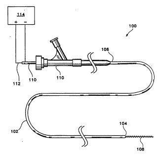
Figure 1 shows a side view of a generic
catheter assembly utilizing the invention.
~ W096/00034 ~1~ 7 9 11 PCT~S95/07954
Figures 2 through 4 show side-view, partial
cross-sectional views of various catheter tips made
according to the invention.
? Figures 5 and 6 schematically depict a method
5 for deploying the vasoocclusive device.
.,
Description of the Invention
Figure 1 shows a side view of a generic
catheter assembly (100) made using the inventions
10 described herein. In general, the assembly employs a
catheter body (102) which has a distal end (104) and a
proximal end (106). The catheter may be of the design
noted above in referring to Engelson (U.S. Patent No.
4,739,768), although it is not critical that such
15 catheter body design be used in this invention. Other
catheter bodies are also suitable in various
circumst~ances. Whatever the catheter design, however,
there must exist at least one lumen passing between
distal end (104) and proximal end (106). Passing through
20 the lumen of catheter body (102) are a collection of
components. In particular, detachable coil (108)
emanates from distal end (104) as the coil is deployed.
A pusher (110) may be used to push the detachable coil
(106) from the distal end (104) of the catheter body
(102). When used, core wire (112) extends from the
catheter body's distal end (106) through pusher (110) and
into the center of detachable coil (108). In this
configuration, the circuit for electrolytically detaching
a desired portion of detachable coil (108) passes through
a conductive path found in the pusher (110) and the core
wire (112). A small gap desirably is found between the
detachable coil (102) and the electrode found on the
distal region of the core wire (112). The power supply
(114) is found in Figure 1. In general, we have found
that tapered core wires (112) are especially suitable for
W096/00034 ~ 79 1~ PCT~S95/07954
this inventive procedure and device in that they tend to
lessen the friction of the core wire against the various
interior parts of the catheter assembly (100). The core
wire (112) will typically be covered with an insulating
material (as will be discussed in more detail below) with
an insulating material such as polyfluorocarbons (e.g.,
Teflon), polyurethane, polyethylene, polypropylene, or
other suitable polymeric material. The electrode, which
will also be discussed in more detail below, is not
covered with the electrical insulator and is of a
material that should not dissolve in the blood upon
imposition of the voltage. Indeed, the core wire (112)
should, in the region of its distal section, at least, be
of a metal which is more noble than that found in the
detachable coil (108). The core wire (112) is typically
10-50 mils. in diameter and is of stainless steel or the
like. We have found that gold plating the distal tip
provides significant resistance to electrolytic
disposition. The core wire (112) and, indeed, the entire
catheter assembly (100), is typically between 50 and 300
cm. in length. Obviously, the length of the catheter
assembly (100) is chosen based upon the use to which the
device is to be placed.
Figure 2 shows one variation of the invention
in which the core wire (116) is immobile with respect to
the distal end (104) of the catheter body. As was noted
above, core wire (116) is coated with an insulator up to
the region of the distal electrode (118). Distal
electrode (118) is, of course, left uncoated so to allow
an electrical path to form through the liquid surrounding
it to the detachable coil (108). The pusher (110) is
also depicted in Figure 1. This variation of the device
operates in the following fashion. The pusher (110)
pushes the detachable coil (108) through the catheter
body (104) until the desired length of detachable coil
~67~1~
_ W096/00034 PCT~S95/0795~
(104) has emanated through the distal end of the catheter
lumen. The immobile core wire (116) does not move with
respect to catheter body (104). This variation permits
the attending physician to understand that the length of
the detachable coil (108) which extends beyond the tip of
the catheter is the length of detachable coil (108) which
will be left at the selected vasoocclusive site.
It should be apparent that the electrode (118)
found at the tip of immobile core wire (116) should, at
once, be both open to the fluid in the vasculature so to
allow the electrolysis to take place but also not be
allowed to contact the interior of coil (108) lest a
direct short take place. A shroud or protector is
desirably placed over the electrode (118). The core wire
(116) itself is insulated proximally of the electrode
(118). Preferably such inherently slippery polymers as
polyfluorocarbons (such as PTFE, FEP), polysulfones or
the like are desirable as such coatings.
Figure 3 shows another variation of the
invention. As was the case with Figure 2, the distal end
(104) of the catheter body is shown as is pusher (110).
In this instance, the detachable coil (108) may be
electrolytically severed outside of the catheter body
distal tip (104). This is accomplished by use of a
movable core wire (120). By "movable", we mean that it
may be axially moved within the inner lumen of coil (108)
and with respect to the distal tip of (104) of catheter
body. This variation clearly allows the attending
physician to trim the length of detachable coil (108) at
some determinable point outside of the catheter. This
may be desirable, for instance, when occluding an
aneurysm. In this way, the distal tip of (104) of the
- catheter body is positioned near the opening of the
aneurysm, the proper length of detachable coil (108) is
then placed through the mouth of the aneurysm into the
~ ~79~ 1
W096/00034 j~ PCT~S95/0795
sac, and the electrode (122) on core wire (120? is then
inserted just into the aneurysm so that during
electrolytic dissolution of a small section of the coil,
the dissolution takes place within the aneurysm sac
beyond the aneurysm neck. This prevents any small
sections of coil remaining out in the artery to form
other non-desired emboli.
Figure 4 shows another variation of the
inventive device in which no core wire is used. As was
the case with the variations shown in Figures 2 and 3,
the device employs a pusher (110) and a detachable coil
(108). However, in lieu of the electrode found interior
to the detachable coil (108) found in Figures 2 and 3,
the electrode (124) in this variation is found on the
interior of catheter distal section (126). This
configuration has many of the same benefits as does the
variation shown in Figure 2 in that the attending
physician is cognizant of the amount of coil to be left
at the desired occluded site because that amount of coil
equals that amount seen emanating from the distal tip
(126) of the catheter body.
The catheter body in this variation has
included within its wall (or otherwise provided for), a
conductor which extends from the proximal end of the
catheter (106) (in Figure 1) to the electrode (124). It
should be apparent that pusher (110) completes the
circuit through the detachable coil (108) either by
inclusion of a conductive wire in the wall of the pusher
(110) or by a discrete wire passing through the lumen of
the pusher. In the variations shown in Figures 2 and 3,
it is more desirable to place the conductor in the wall
of the pusher since in that way, the movement of core
wire (116) (in Figure 2) and core wire (120) (in Figure
3) is not impeded. In the variation shown in Figure 4,
the conductor associated with the proximal end of
;
~ 679~1
~ W096/00034 PCT~S95107954
,~
detachable coil (108) may either be placed within the
wall of pusher (110) or through the lumen found in the
midsection. Indeed, in certain short catheter assemblies
(100) (in Figure 1) may be completely metallic. It is
within purview of this invention that other means of
conducting electricity to the proximal end of the
detachable coil (108) are reasonable, but such does not
form the core idea of this invention.
As was the case in the variation found in
Figure 3, the electrode (122) should be provided with a
protector or shroud to allow the contact of the metallic
electrode (122) with blood but not to allow the electrode
to contact the interior of coil (108). Also as was the
case with immobile core wire (116), the core wire (120)
is insulated proximally of the metallic tip (122)
preferably with a lubricious polymer.
The detachable coil (108) shown in each of the
drawings above is shown to be a coil. Indeed, it may be
a coil or it may be some other vasoocclusive form such as
a braid or a combination of braids and coils. A coil is
desired because it more readily severs electrolytically
at a single point. Electrolytic dissolution of multi-
fibered braid is complicated by the presence of multiple
electrolysis points. The diameter of the wire used in
such braid is typically much smaller than would be used
in a coil but, again, the dissolution process is
inherently more complicated. Additionally, it is within
the purview of this invention to cover the vasoocclusive
device or connect the vasoocclusive device with fibrous
materials. The fibrous materials may be materials which
cause the vasoocclusive better to form a thrombus.
Fibrous materials such as Dacron and the like are
acceptable. Fibrous adjuvants such as found in U.S.
Patent Application No. 07/965,973, to Phelps et al., or
in U.S. Patent No. 5,226,911 to Chee et al. entitled
W096/00034 ~ g ~ PCT~S95/0795
~Vasoocclusion Coil with Attached Fibrous Elements", the
entirety of which are incorporated by reference, are
acceptable.
Figures 5 and 6 show a typical layout involving
the inventive device as was generally described in the
Figures above but particularly with regard to Figure 3.
In Figure 5, a core wire (120) having an electrode (118)
at its distal section is coated with an insulation
material such as Teflon throughout its length except at
the electrode (118) . This core wire (120) is placed
within pusher (110). As was noted above, the core wire
(120) is typically of a diameter of approximately 10-30
mils., although such size is not critical. In the
embodiment shown in Figure 5, the core wire (120) is
tapered to its distal end. The vasoocclusive coil (104)
is pushed from the catheter into the aneurysm sac (130)
through aneurysm neck (132). Preferably, detachable
vasoocclusive device (108) when a coil, forms a secondary
loop after it leaves the end of the catheter. The most
distal end (134) of detachable coil (108) may also have
an end plug or tip of some type simply to prevent
punctures of the aneurysm as it is introduced into the
aneurysm sac. As noted, the detachable coil (108) may be
prebiased to form a cylinder or a conical envelope. The
coil may be heat treated or crimped or otherwise
physically treated to form a random shape after it is
ejected from the catheter. It is desirable that a
significant volume of the aneurysm be filled with the
vasoocclusive device. Consequently, it is desirable that
the device be quite flexible so to allow its conformance
to the inner wall of the aneurysm without puncture. In
any event, once the coil is properly placed within the
aneurysm and the attending physician positions the
electrode ( 118 ) so to trim a proper amount of the
detachable coil (108) into the aneurysm, a modest voltage
~6~
~ W096/0~034 PCT~S95/07954
1 3
is then applied to the device. In particular, a positive
electric current of approximately 0.1 to 2 milliamps at
0.1 to 5.0 volts is applied to core wire (120) so to form
a thrombus within aneurysm sac (130). The negative pole
of power supply (114) is attached to the conductor
passing through or along the pusher (110).
After the thrombus (140) has been formed (as
shown in Figure 6) and the aneurysm occluded, the core
wire (120) with its electrode (118) is withdrawn as is
the distal portion of the catheter (104). This removal
typically takes place within three to ten minutes,
leaving aneurysm sac (132) occluded as is shown in
Figure 6.
The process is typically practiced under
fluoroscopic control with local anesthesia. A
transfemoral catheter (of which (104) is the distal
sec~ion) is utilized to treat a cerebral aneurysm. In
much heavier patients, the catheter may be introduced
into the carotid artery.
Many alterations and modifications may be made
by those having ordinary skill in the art without
departing from the spirit and scope of this invention.
Therefore it must be understood that the concept of
electrolytically determining the length of a
vasoocclusive device such as described herein is the
concept of this invention and may be provided for in a
variety of shapes.
The illustrated embodiments have been used only
for the purposes of clarity and should not be taken as
limiting the invention as defined by the following
claims.