Note: Descriptions are shown in the official language in which they were submitted.
~1~8141
E-345
DIFFERENTIAL FELTING OF A FOAM FOR IMPROVED METERING OF
INKS AND OTHER LIQUIDS
Field Of The Invention
The invention relates generally to the field of ink metering systems and
more particularly to ink metering materials and printing elements.
Background of the Invention
In the printing operation of the impact type, a drum / plate is provided
with ink, by an ink roller or ink pad, immediately before making contact with
a
medium such as paper. The inking member can be one of two types, one
io wherein ink is supplied continually to the inking member and the other
where
the inking member stores a quantity of ink and is replaced when that quantity
of ink has been consumed. In a system where ink is continually supplied, a
method of replenishing the ink must be provided. The method, for example
may be a pump attached to a reservoir for a flat bed ink pad printing system.
is With regard to a self containing inking member, the advantages reside in
not
requiring a mechanism for supplying ink to the inking member, but the
disadvantage is that the inking member must be replaced from time to time on
a much more frequent basis. There is also a tendency for the print intensity
to
vary from dark to light as the ink in the roller or pad is slowly depleting.
The
2o instant invention is directed to an inking member that is capable of
storing a
relatively large quantity of ink, yet is able to meter the ink efficiently.
Although
the ink member has primary advantages as a self contained inking layer, the
ink member can be used either as the print plate (element) for transferring
print
characters (fonts or patterns) or as an ink transferring medium to supply ink
to
2s a dedicated (separate) print plate.
One of the methods used by the prior art to manufacture printing
elements and ink transfer members or metering materials is to manufacture the
foregoing from porous polymeric materials prepared specifically for a given
application. One such method is to mix a filler (also known as a pore forming
3o material) with a polymer, and to remove the filler by a leaching process
after
2168141
__ 2 __
completing a series of steps to make the product. If the filler is a water
soluble
salt, the filler is leached away with water, othenivise the filler is leached
with a
suitable organic solvent. The foregoing allows pores to be formed in the
metering material. The size and shape of the pores are controlled by the
s screened size (mesh size) and shape of the filler. The polymer and the
filler
are intimately mixed first with or without external heating, and then
subjected to
compression molding or extrusion, to get to the near net shape of form before
the filler is leached to remove the filler and create the pores. During the
molding or extrusion step or in a separate step the porous material thus
formed
io is further processed to form ink metering pads, rollers or actual printing
elements. The foregoing porous material provides void volumes for holding
inks.
One of the disadvantages of the foregoing is that the filler must be
carefully controlled to maintain the pore size distribution.
is Another disadvantage of the foregoing is that the ratio of polymer to
filler must be carefully controlled. If the ratio of polymer to filler is
high, the
filler may become encapsulated and can not be washed out. Also, if the ratio
of polymer to filler is high, even if the filler is leached out, the resulting
material
will have closed cell pores in which fluids can not flow through. If the ratio
of
2o polymer to filler is low, then the metering material may not be moldable or
extrudable. Also the final dimensions and mechanical properties are critically
dependent on the initial polymer - filler ratios. Certain fillers like sodium
nitrate
may also be a fire hazard, either during sizing or incorporation during
fabrication that generate or involve high temperatures. Also special
2s precautions are needed in such mixing, since the fillers consist of very
fine
particles (static charge build up).
An additional disadvantage of the foregoing is that the prior art leaching
process generates waste fluids which must be properly disposed resulting in
an increase in the cost of the process.
3o Another method used by the prior art to manufacture printing elements
and ink members or metering materials is a process that involves the mixing of
liquid plasticzers, polyvinyl chloride and ink disclosed in U.S. Patent No.
3,971,315 entitles "Macroporous Micoporous Marking Structure" by Frederick
21681~I
-3--
C. Hansen. The process alleges to assist pore size distribution of wider
ranges, but still has all the disadvantages associated with the generic
polymer
- filler processes. In addition the material has multiple layers and each
layer
has to be processed separately before combining the layers and hence the
s entire fabrication tends to be labor intensive.
A further disadvantage of the above process is that a skin is likely to
form on the surface of the material during the processing. The skin prevents
the controlled flow of ink from the interior of the material to the outer
surface of
the material. Thus, an additional grinding step may be required to open the
io pores on the skin surface.
Another method used by the prior art to manufacture printing elements
and ink members or metering materials is a process that utilizes physical or
chemical blowing agents. Physical blowing, for example involves the supplying
of air or a gas into liquid monomers before polymerization and curing. One of
is the problems encountered with physical blowing is controlling the size,
shape
and interconnection of pores. Hence, control of the optimum physical
properties is difficult.
A disadvantage of the foregoing is that there is a large variation in
properties of the material within a batch and from batch to batch.
zo Chemical blowing agents like 2, 2' - Azobis (isobutyronitrile) or ADN
would achieve the same result as physical blowing. The disadvantages of
chemical blowing agents (CBA) are their high cost and in some cases their
toxicity. CBA may also decrease the thermal stability of the polymer by
leaving
embedded thermal decomposition products.
2s Another commonly used practice is to make composite materials
consisting of different layers of the same or different polymeric materials of
different pore size distributions together by joining them with adhesives or
other means. The disadvantages of such procedures is that selection of
mutually compatible materials is difficult. The use of an adhesive adds
3o problems of proper bonding without blocking the pores, thus reducing the
flow
properties. The adhesives may have a tendency to separate during use due to
the ink solvents.
4
21s8~41
Summary of the Invention
This invention overcomes the disadvantages of the
prior art by providing a secondary process that forms a
differentially felted foam from off-the-shelf open cell
thermoset or thermoplastic polymers. A material or print
element, thus formed distributes inks and other fluids
uniformly, while acting as an effective reservoir with a
capacity to deliver ink only on demand. The above
felting process produces a density gradient of pore size
in the thickness direction within the material to aid in
such improved metering of inks and other fluids. In
other words, the top surface of the metering material may
have pores that are generally small in size, the middle
layer of the metering material may have pores that are
generally of medium size, and the lower layer of the
metering material may have pores that are generally large
in size. The process also does not close the pores on
the top surface. Thus, a skin is not formed which
subsequently has to be removed. The material may also be
used as printing elements, with the characters or
patterns molded on the top surface (finer pore surface)
that can be accomplished during the felting process. The
print patterns can also be generated in a subsequent
etching or molding step.
The process that forms the differentially felted
foam involves the directionally controlled application of
pressure and heat to the off-the-shelf open cell foam
polymers. The above process causes a permanent graded
compression set in the foam material. Examples of such
thermoset or thermoplastic foraminous or porous open cell
foams are polyurethanes, polyolefins, polyethylene,
neoprene (chloroprene) and melamine - formaldehyde.
In accordance with an aspect of the present
invention is a composition of matter that serves as a
fluid dispensing member after fluid is added thereto,
which comprises of:
a one piece body composed of an open cell porous
thermoset or thermoplastic material having a density
A
4a 2 1 6 8 1 4 1
gradient of pore sizes, the porous material having a
first layer with a thickness between 0.4 mm and 1.4 mm
and having generally small pore sizes from l0u to 80u; a
second layer confluent with the first layer with a
thickness between 1 mm and 1.3 mm and having generally
medium pore sizes between 40u to 150u; and a third layer
confluent with the second layer with a thickness between
2.5 mm and 3.0 mm and having generally large size pores
between 100u to 300u to aid in the retention and metering
of fluids.
In accordance with yet another aspect of the present
invention is a method of making an ink pad from a
urethane foam having a density gradient of pore sizes to
aid ink flow, the steps comprising:
placing a sheet of an open cell urethane foam in a
press between two platens,
heating one of the platens of the press to a
temperature between 380 to 450°F,
placing a shim having a thickness smaller than the
thickness of the sheet of foam between the platens,
positioning the quantity of foam within the shim
with a layer of the foam extending between the shim and
the heated platen before pressure is applied, and
applying pressure to the heated platen until the
heated pad engages the shim.
Brief Description of the Drawin s
Fig. 1 is a drawing of a cross sectional view of the
foraminous material before differential felting;
Fig. 2 is a drawing of a cross section view of the
material of Fig. 1 after differential felting; and
218141
--5-
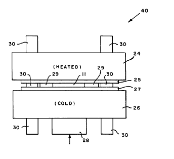
Fig 3 is a schematic drawing of the press used for differential felting.
Detailed Descriation of the Preferred Embodiment
Referring now to the drawings in detail, and more particularly to Fig. 1,
the reference character 11 represents a open cell thermoset or thermoplastic
s foraminous material. Examples of thermoset or thermoplastic foraminous
materials are polyurethanes, polyolefins, polyethylene, neoprene (chloroprene)
and melamine - formaldehyde. The pores 10 of material 11 have a size of
approximately 10 p, to 300 p,. Pores 10 are randomly distributed throughout
material 11. Although there is a wide range of pore 10 sizes, material
consists
io mostly of the larger pores, close to the top of the range mentioned here.
Pores
of size 150p,. and above are, therefore, more prevalent in the off-the-shelf
material.
Fig. 2 is a drawing of a cross section view of material 11 of Fig. 1 after
differential felting. The process in which differential felting is performed
will be
is hereinafter described in the description of Fig. 3. After material 11 is
differentially felted it will be shown as material 12. Material 12 may be used
as
an ink transfer member or in an ink cartridge in an impact printer or made
into
a print plate. The inking member is shown generally at 12 in the form of a pad
and has a top layer 13 that serves as a metering layer having generally small
ao pores 14 therein. The pores 14 of the top layer 13 can have a size of
approximately 10 p, to 80 p,. Confluent with the top layer 13 is a middle
layer
that generally has medium pores 17. Pores 17 may serve as an ink
reservoir and have a size of 40 ~, to 150 ~. Confluent with the middle layer
15
is a bottom layer 19 that generally has large pores 20. Pores 20 may serve as
zs an ink reservoir and have a size of 100 p, to 300 p.
It is to be understood that the change in pore size effected by the
process described herein is rather gradual and there is no sharp demarcation
between the top layer 13, the middle layer 15 and the bottom layer 19. In
other
words the pore sizes will overlap and between any two layers mentioned
3o above, there may be zones with pore sizes that fall in-between. The
21G814t
__6_
identification of the top layer 13, the middle layer 15 and the bottom layer
19
are only to illustrate the phenomenon.
The top layer 13 is contacted by the print elements of a printhead for the
purpose of having the pad 12 supply ink to such fonts. After contact with the
s print pad 12, the fonts would contact a medium such as paper to transfer ink
thereto and complete the printing operation, as is well known in the art. The
top layer 13 acts as metering layer and will release ink slowly on demand upon
the application of pressure to control the amount of ink supplied to the fonts
of
a printhead. As ink is transferred from the top (metering) layer 13 to the
fonts,
io replacement ink is supplied from the middle layer 15 to the top layer 13,
because of their confluence. The middle layer 15 acts as an ink reservoir and
has generally medium pores 17 that are capable of holding quantities of ink.
As ink is transferred from the middle layer 15 to the top layer 13 ink is also
transferred from the bottom layer 19 to the middle layer 15. The bottom layer
is 19 acts as the main ink reservoir and has generally larger pores 20 that
are
capable of holding large quantities of ink. Needless to say, after the ink has
been sufficiently depleted in the course of the printing operations, the pad
12
would be replaced with a pad having a full supply of ink if it were not
supplied
with ink continually.
Zo The monotonic change in pore sizes from bottom layer 19 to middle
layer 15 to top layer 13, thus determine the formation of a distinct main
storage
layer for ink at the bottom layer 19, a transfer layer in the middle layer 15
and a
metering layer in the top layer 13.
Fig 3 is a schematic drawing of the press 40 (under a closed state) used
2s for differential felting. Press 40 comprises: a top platen 24 that is
coated with a
layer of Teflon~ 25; a bottom platen 26 that is coated with a layer of Teflon~
27; a ram 28; and shims or molded cavity 29. Top platen 24 and bottom platen
26 may be moved up and down slides 30 so that material 11 may be placed
between shims or molded cavity 29 between platens 24 and 26. The
3o differential felting process is accomplished by heating the top material 11
thereto. Fig. 1 is a drawing of a cross section of the foraminous material 11
before the differential felting process and Fig. 2 is a drawing of the
foraminous
~16814~.
__ 7 __
material 11 after the differential felting process, when material 11 becomes
material 12.
Material 11 can be any suitable foraminous material such as
polyurethane, polyethylene, other polyolefines, polychloroprene, melamine -
s formaldehyde and the like. The important consideration is that the
foraminous
material be an open cell foam and that it be compatible with the ink that is
to
be dispensed. It should also have all the other mechanical properties (like
tensile and flex moduli, compressibility, hardness, density, curl, indentation
force, etc.) Fluid flow properties are also very essential. One preferred
io material is polyurethane, for the class of inks that are described in U.S.
Patent
Nos 5,114,478 and 5,091,006 incorporated herein by reference.
The following example describes the differential felting process for the
material 11, when the material 11 is a polyurethane foam.
The method of controlling the density of the top layer 13 (Fig. 2) is by
is creating a compression set of a fixed thickness of material 11, while
maintaining interconnectively of the pores. A material 11 having a length of
130 mm and a width of 38.6 mm and a thickness of approximately 6.2 mm was
placed on top of the bottom platen 26 of a press 40 and between two shims or
molded cavity 29. The top platen 24 of the press 40 was heated to a
ao temperature of 380 to 450°F and a load of approximately 8,000 to
9,000 kg of
force on 165 mm ram press 28 was applied to the bottom platen 26 for 2.5 to
3.5 minutes. It should be noted that the load is not critical as it is only
necessary that the top platen 24 engage the shims or molded cavity 29. The
height of the shim or the molded cavity 29 determines the final thickness of
as material 11. Typically the molded cavity or shim 29 will have a thickness
between 4.4 to 4.8 mm which is less than the original thickness of material
11.
This yielded a top layer 13 (Fig. 2) with a thickness in the range of 0.4 mm
to
1.4 mm. Preferably, the top layer 13 thickness will close to 0.762 mm. The
middle layer 15 is also formed during the above process and it has a thickness
30 of 1 mm to 1.3 mm and the thickness of the bottom layer 19 will be 2.5 mm
to
3.0 mm. The variables like pressure, temperature and time of the "felting"
process are optimized for each end use that takes into consideration the ink
solvents, solid contents, viscosity, surface tension and amount of ink
2~ss~4~
__8_
transferred during each print cycle etc. The selection of the polymeric
material
is critically important since polymeric swell is strongly dependent on the
nature
of the solvent.
In a preferred embodiment, any suitable mold release agent can be
s used, i.e. a polytetrafluoroethylene coated plate having a thickness of
approximately 6.0 mm was placed between the top platen 24 and the material
11. Clearly, in place of layers 25 and 27, the contacting surtace of platens
24
and 26 could be coated with polytetrafluoroethylene, or any suitable mold
release agent.
to The foraminous material described herein is a special class of
polyurethane because of its versatility and compatibility with the ink for the
intended application. The physical properties like compression strength,
firmness, conformance, compliance, tear, elongation, tensile and flexural
moduli, etc. of this class of urethanes are ideally suited for the said
application.
Is The material has good wear strength and the required swell characteristics
for
the class of inks in question. These factors control the ink hold out, flow
and
pay out and is also a critical requirement, for the long term mechanical and
chemical stability of the material.
More important is the fact that the excess ink left behind after the print
Zo cycle is re-absorbed rapidly into the lower layers of pad, and hence there
is no
pooling of ink on the top surface. In addition, minimum gaseous products are
generated during the felting process. Ink does not tend to run out of the pad
during shipping, handling and storing. At ambient temperatures the inked pads
have good dimensional stability and do not undergo chemical decomposition
Zs over a period of time after impregnation with said inks.
The properties of the urethane selected for the above example are as
follows.
Foam material SIF (Standard Industrial Foam) Felt (8-900Z) is the raw
material for this ink pad application. The foam is polyurethane-polyester
3o reticulated (open pore) prefelted (permanently compressed) foam from Foamex
inc. of 3005 Commercial Road, Fort Wayne, IN 46809. The number 900
indicates that the foam has 90 pores per linear inch before felting. The
number 8 signifies that the prefelted foam is compressed 8:1 of the original
~~.fi8141
__ g __
thickness. This is also called firmness of the material. The "Z" represents a
zapping process to insure reticulation, or obtain confluent pores.
Physical Properties of Foamex SIF felt (8-900Z) foam
Grade: 900
s Firmness: g
Color: Natural (Beige), no artificial coloring.
Density: 14 to 18 Ib./cu. ft ASTM D 3574
Elongation: 425% ASTM D3574
Air Permeability: 70 to 120 ml/min
to (Digital Air Flow Meter)
The properties of the differentially felted product in the above example
are as follows:
Pro a Saecification
Pad curl 0.5 inch max.
is Indentation Force 3 to 4 Ib.
Deflection (25%)
Air Permeability Top Surface
(Digital Air Flow Meter) 13 to 30 ml/min.
Bottom Surtace
20 (Digital Air Flow Meter) 70 to 120 ml/min
Weight of The Dry Pad 6.3 to 7.6 grams
The following example describes the differential felting process for the
material 11, when the material 11 is Willtec~.
The method of controlling the density of the top layer 13 (Fig. 2) is by
2s creating a compression set of a fixed thickness of material 11, while
maintaining interconnectively of the pores. A material 11 having a length of
130 mm and a width of 38.6 mm and a thickness of approximately 5.1 mm was
placed on bottom platen 26 of a press 40 and between two shims or molded
cavity 29. The top platen 24 of the press 40 was heated to a temperature of
30 550 to 600°F and a load of approximately 600 to 1000 kg of force on
165 mm
ram press 28 was applied to the bottom platen 26 for 7.0 to 10.0 minutes. It
should be noted that the load is not critical as it is only necessary that the
top
X168141
-- 10 --
platen 24 engage the shims or molded cavity 29. The height of the shim or
molded cavity 29 determines the final thickness of material 11. Typical shim
29 will have a thickness between 4.4 to 4.8 mm less than the original
thickness
of material 11. This yielded a top layer 13 (Fig. 2) with a thickness in the
s range of 0.4 mm to 1.4 mm. Preferably the thickness is close to 0.762 mm.
The middle layer 15 is also formed during the above process and it has a
thickness of 1 mm to 1.3 mm and the thickness of the bottom layer 19 will be
2.5 mm to 3.0 mm. The variables like pressure, temperature and time of the
"felting" process are optimized for each end use that takes into consideration
io the ink solvents, solid contents, viscosity, surface tension and amount of
ink
transferred during each print cycle etc. The selection of the polymeric
material
is critically important since polymeric swell is strongly dependent on the
nature
of the solvent.
In a preferred embodiment, any suitable mold release agent can be
is used, i.e. a polytetrafluoroethylene coated plate having a thickness of
approximately 6.0 mm was placed between the top platen 24 and the material
11. Clearly, in place of layers 25 and 27, the contacting surtace of platens
24
and 26 could be coated with polytetrafluoroethylene, or any suitable mold
release agent.
ao The foraminous material described herein is a special class of
melamine-formaldehyde because of its versatility and compatibility with the
ink
for the intended application. The physical properties like compression
strength, firmness, conformance, compliance, tear, elongation, tensile and
flexural moduli, etc. of this class of melamine-formaldehyde is ideally suited
for
2s the said application. The material has good wear strength and the required
swell characteristics for the class of inks in question. This factor controls
the
ink hold out, flow and pay off and is also a critical requirement, or the long
term
mechanical and chemical stability of the material.
More important is the fact that the excess ink left behind after the print
3o cycle is reabsorbed rapidly into the lower layers of pad, and hence there
is no
pooling of ink on the top surface. In addition, minimum gaseous products are
generated during the felting process. Ink does not tend to run out of the pad
during shipping, handling and storing. At ambient temperatures the inked pads
218141
__ 11 __
have good dimensional stability and do not undergo chemical decomposition
over a period of time after impregnation with said inks.
Willtec~ is a melamine based polymer, extremely low density, flexible
open cell foam. It has very good chemical resistance properties. The table
s below provides some of the physical properties.
Grade: Off the Shelf
Firmness: Non Felted
Color: White
Density: 0.5 to 0.7 Ib./cu. ft.
io Elongation: 8%
Air Permeability 600 to 700 ml/min. (digital Air Flow Meter)
Pore size: 175 to 300 microns
This low density Willtec is taken through a prefelting step to compress
the material. The properties of the prefelted material are as follows:
is Proaerty Specification
Grade: Differentially Felted Pad
Firmness 2.5
The prefelted 2.5 firmness material is then taken through the differential
felting process. The properties of the differentially felted material in the
above
2o example are as follows.
Pad Curl: 0.5 inch Max.
Weight of Density Dry Pad 0.7 to 0.8 grams
Air Permeability: Top 500 to 550 ml/min.
Bottom 550 to 600 mllmin.
2s Property Specifications
Pore Size:
Top 40 to 80 microns
Transition 80 to 150 microns
Bottom 150 to 200 microns
3o If other open cell foams are chosen, felting temperature, pressure and
dwell time will be selected to give the optimum properties for the final
product.
2168141
__ 12 __
If for e.g., Neoprene (chloroprene) is used as the starting material 11, then
the
temperature of the top plate 24 is maintained between 480-500° F., and
a
pressure of 10,000 to 12,000 kg. used. A dwell time of 3 to 4 minutes is
necessary.
s Although the invention is described as applied to an inking pad, it could
be utilized equally well with other forms of inking members such as inking
rollers, ink cartridge as well as print plates. It could also be used to wick
ink
more rapidly in an ink cartridge.
The advantages of the instant printing pad and method of making is that
io of simplicity in manufacture and versatility of the material that results
in
improved quality in an inking member at a much lower cost. No special
occupational safety procedures other than standard safe manufacturing
practices are required. Furthermore, no effluent streams of ligands or gases
are involved. When used as a self contained inking member it had a life of
is 10,000 printing cycles. The fact that only one elastomeric foam material is
used to form the graded density pad is advantageous since quality control can
be more easily achieved. Furthermore, one need not be concerned with
adhesive losing its properties with the passage of time as could occur with
prior dual or multiple density inking members joined mechanically or by
2o adhesives.
The above embodiments have been given by way of illustration only,
and other embodiments of the instant invention will be apparent to those
skilled in the art from consideration of the detailed description.
Accordingly,
limitations on the instant invention are to be found only in the claims.