Note: Descriptions are shown in the official language in which they were submitted.
.- _ 2168175
769-178
Method for Stabilizing a Plastic Zipper
Durinq Attachment to a Film
Back~round of the Invention
1. Field of The Invention
This invention pertains to the art of reclosable
plastic bags having extruded zippers, and more
particularly to a reclosable bag having fastener
profiles including wedge-shaped stops, which
facilitate the joining attachment of the fastener
profiles and which determine the amount of pull force
~required to open the bags. The fastener profiles are
further of a design which makes inadvertent opening of
the bags less likely.
The present invention also relates to reclosable
plastic bags requiring a greater pull force to be
opened from within than from without, and to a method
for substantially reducing the variance in the forces
required to open such bags from within and from
without, as well as the consequent variability in the
ratio between those forces.
The present invention further relates to a method
for stabilizing and aligning the profiles of a plastic
zipper during its attachment to a sheet of polymeric
film, such as that used to make reclosable bags.
2. DescriPtion of the Prior Art
Reclosable bags used, for example, for storing
household foodstuffs are typically made of
2 1 68 1 75
polyethylene. As shown in U.S. Patent No. 3,416,199
to Imamura c~o.,u..o~ly assigned with the present
invention, a reclosable bag may be formed of two
opposed walls equipped at the mouth with fastener
-5 profiles. These profiles include a male profile
attached to one wall and a female profile on the other
wall. The profiles are shaped so that, when they are
aligned and pressed together into an engaging
relationship, they form a continuous closure for the
bag. The bag may be opened by pulling the walls apart
thereby separating the profiles. Various geometric
shapes and arrangements for such profiles are shown in
U.S. Patents Nos. Re. 28,969; 3,323,707; 4,212,337;
4,363,345; 4,561,108; and 4,812,056. In addition,
U.S. Patents Nos. 4,736,496 and 5,012,561 disclose
reclosable bags with profiles and internal ribs
adjacent to the profiles. U.S. Patent No. 4,822,539
discloses a~reclosable bag with interlocking profiles,
internal guiding ribs disposed adjacent to the
profiles, and stabilizing beams disposed on the
outside surface of the bag wall. U.S. Patent No.
3,338,285 discloses a reclosable bag having several
parallel interlocking male and female profiles. In
general, the profiles must be such as to provide
relatively high resistance to opening from inside the
bag while rendering the bag relatively easy to open
from the outside.
For the zipper to function properly, it is
important that the zipper components (i.e. the
profiles and any wedges, beams, ribs or the like
provided to enhance the operation of the profiles)
maintain their alignment. The problem of maintaining
the alignment of the components of the zipper is
exacerbated where the zipper is in string or strip
form to be heat sealed to a film material from which
^ - 21 681 75
the body of the bag is to be formed, since the heat
necessary to fuse the zipper strip to the film could
distort the profiles or a zipper component.
Heretofore, the problem has been avoided by adding
webs to the zipper strip to separate the profiles (and
components) from the point of attachment-to the film.
In U.S. Patent No. 4,673,383 a zipper strip is
disclosed having fusible ribs on its undersurface to
minimize the heat to which the zipper is subjected.
In U.S. Patents Nos. 4,691,372; 4,731,911; and
- 4,817,188, an adhesive layer is provided on the base
of the profile portion of the strip.
Another aspect of the problem of maintaining the
alignment of the components during heat-sealing to a
film material is reflected in the ability of the
profiles to rock relative to one another about a
longitudinal axis because a male interlocking member
~may pivot within a female interlocking member about
such an axis. This ability to rock or pivot presents
an instability of the two profiles relative to one
another which may have an adverse effect on the
quality of the heat-seal between the profiles and the
film material.
Summarv of the Invention
In view of the above, an objective of the present
invention is to provide~a reclosable bag with improved
closure means resistant to inadvertent opening.
Another object is to provide such closure means
in the form of a zipper strip which may be heat-sealed
to an associated film without distorting the zipper
profiles or any of the components of the zipper.
Yet another object of the present invention is to
provide a method for stabilizing and aligning
interlocked male and female profiles of a plastic
zipper strip during attachment of the strip to a
2 1 68 1 75
polymeric film to eliminate or substantially reduce
the freedom of the profiles to rock relative to one
another about a longitl~;n~l axis and the consequent
loss of uniformity and consistency in the heat-seal
between the profiles and the polymeric film.
Other objectives and advantages of the invention
will become apparent from the following description.
A reclosable bag constructed in accordance with this
invention includes a front wall and a rear wall joined
to form an enclosure with a mouth defined by wall
edges at the top of the bag and male and female
profile means having male and female members for
selectively opening and closing said mouth.
Stabilizer wedges are provided on each of the male and
female profile means. Specifically, a stabilizer
wedge is provided on each side of the male and female
members on the male and female profile means. The
wedges keep the zipper parallel during the application
of the zipper to the film from which the bag is made
and have a stabilizing effect during the attachment
process. Further, the wedge action controls the force
required to open the bag, and substantially increases
the inside resistance to opening pressure from the
product within the bag. Finally, the stabilizer
provides the zipper as a whole with a wide-track feel
for the benefit of the consumer.
The profiles are provided on zipper strips heat-
sealed to the front and rear walls of the bag. To
facilitate the heat-sealing, a layer of a material
having a lower melting temperature than the zipper
strips and the bag material is provided underlying at
least a portion of the zipper strip width so that the
zipper may be heat-sealed to the bag walls at a
temperature sufficiently low to prevent distortion of
the profiles or wedges, or of the bag material. The
2168175
lower-melting-point material may underlie only a
portion of the zipper width, so that a hinged
connection is provided between the zipper strip and
bag wall. The lower-melting-point material may, for
-5 example, be a high ethylene-vinyl acetate (EVA)
material, a high melt index (M.I.) material, a
thermoplastic olefin (TPO) copolymer or polypropylene-
ethylene copolymer, or an ethylene methyl acrylate
(EMA) copolymer.
The use of a lower-melting-point material under
only a portion of the zipper may enable the
manufacturer to fix the position of the seal of the
zipper strip to the bag wall in spite of any lateral
shifting, or "float", thereof permitted by the
equipment used to manufacture the bags. Such is
accomplished by making the lower-melting-point
material in a strip wider than the "float" which may
occur in the equipment. In that situation, the lower-
melting-point material will be melted by the sealing
head, regardless of any shift laterally relative
thereto, and will ensure a seal at a constant position
on the profile.
The present method for stabilizing and aligning
interlocked male and female profiles of a plastic
zipper strip during attachment of the strip to a
polymeric film includes the step of providing a first
profile having a first base with first and second
surfaces. A male interlocking member and a pair of
first stabilizers, one on each side of the male
interlocking member, are provided on the first surface
of the first base.
Also provided is a second profile having a second
base with first and second surfaces. A female
interlocking member and a pair of second stabilizers,
2 1 68 1 75
one on each side of the female interlocking member,
are provided on the first surface of the second base.
When the first and second profiles are joined
together by interlocking their respective male and
female interlocking members, each one of the pair of
-first stabilizers on the first profile is brought
into a position substantially adjacent to one of the
pair of second stabilizers on the second profile. The
adjacent ones of the first and second stabilizers on
each side of the interlocked male and female
interlocking profiles cooperate to maintain the second
surface of the first base substantially parallel to
the second surface of the second base and to prevent
the profiles from rocking relative to one another
about a longitudinal axis. The first stabilizers may
be inward of, outward of, or at the same distance from
the interlocked male and female interlocking profiles
compared to their respective second stabilizers.
Each one of the pair of first stabilizers is
contacted with its respective one of the pair of
second stabilizers while the second surfaces of the
first and second bases of their respective profiles
are attached to polymeric sheet material, so that the
sheet material will be attached to the second surfaces
in a consistent and uniform manner as a result of the
substantial parallelis~ of the second surfaces of the
profiles brought about by the mechanical cooperation
between the stabilizers.
The present invention will now be described more
completely with frequent reference being made to the
drawings identified hereinbelow.
Brief Descri~tion of the Drawinas
Figure 1 shows a plan view of a reclosable bag
constructed in accordance with the present invention;
- `~ 2168175
Figure 2 shows an enlarged side sectional view of
the bag opening;
Figure 3 shows an enlarged side sectional view,
analogous to that presented in Figure 2, of the bag
being opened from the outside; and
Figure 4 shows another enlarged side sectional
view, analogous to that presented in Figure 2, of the
bag being opened from the inside;
Figure 5 shows an enlarged side sectional view of
an alternative embodiment of the bag of the present
invention wherein an interlayer is utilized between
the bag walls and profile strips;
Figure 6 shows an enlarged side sectional view of
a further embodiment of the bag of the present
invention;
Figure 7 is a cross-sectional view of an
apparatus used to seal zipper profiles to plastic
sheet material;
Figures 8A, 8B and 8C show pull test conditions
for measuring the force required to open plastic bags
from without; ..
Figures 9A, 9B and 9C show pull test conditions
for measuring the force required to open plastic bags
from within;
Figure 10 is a cross-sectional view of a pair of
interlocked zipper profiles of the prior art;
Figure 11 is a cross-sectional view of a pair of
interlocked zipper profiles which may be used in the
practice of the present invention;
Figure 12 is a cross-sectional view of an
-alternate embodiment pair of interlocked zipper
profiles which may be used in the practice of the
present invention; and
- ~ 21 681 75
Figure 13 is a cross-sectional view of a third
embodiment pair of interlocked zipper profiles which
may be used in the practice of the present invention.
Detailed Description of the Preferred Embodiment
-5 Referring now to the drawings, and specifically
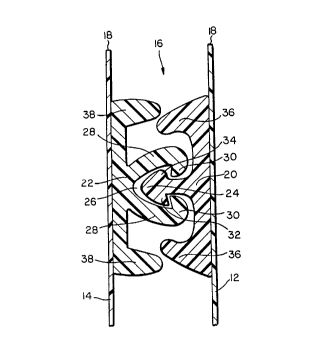
to Figures 1 and 2, a reclosable bag 10 constructed in
accordance with this invention includes front and rear
walls 12,14 seamed along three edges thereby forming
an enclosure with an opening or mouth 16 along thé top
or fourth edge 18. The bag 10 is preferably made of
a thermoplastic material such as polyethylene by
extrusion. Attached to internal faces, walls 12 and
14 are male and female profiles 20,22 respectively,
which extend continuously from side to side of the
bag. The profile serves to close the bag opening 16
when they are interlocked as shown in Figure 2.
The male profile 20 includes an asymmetric
arrowhead 24 which locks into a channel 26 formed by
two inwardly curved members 28 having inwardly
20 pointing stubs 30. The asymmetric arrowhead 24 is so
called because its two barbs are not mirror images of
one another. Barb 32 has an acute edge, while barb 34
has a rounded edge. Barb 34 is closer to the mouth 16
of the bag 10 than barb 32.
The male profile 20 has two stabilizer wedges 36,
which are on each side~of the asymmetric arrowhead 24
and are parallel thereto across the width of the bag
10. The stabilizer wedges 36 are inclined toward one
another and toward asymmetric arrowhead 24.
In like manner, the female profile 22 has two
stabilizer wedges 38, which are on each side of the
inwardly curved members 28 and are parallel thereto
across the width of the bag 10. The stabilizer wedges
38 are inclined away from one another, or, at least,
2168175
have surfaces facing the inwardly curved members 28
which are inclined away from one another.
When the male and female profiles 20,22 are
interengaged as shown in Figure 2, stabilizer wedges
36 protrude to some preselected degree into the spaces
between -the ~tabilizer wedges 38 and the inwardly
curved members 28 on the female profile 22.
Bag 10 is normally opened by gripping edges 18 on
the outside of the bag 10 and pulling them apart. In
response to such action the lower stabilizer wedges
36,38, which are toward the inside of the bag 10, as
shown in Figure 3, abut against one another. This
braces the male profile 20 against the female profile
22, and allows the rounded barb 34 of the asymmetric
arrowhead 24 to glide past its adjacent stub 30 to
open the bag 10. The force required to open the bag
10 may be preselected by appropriately choosing the
angles at which the surfaces of stabilizer wedges
36,38 contact one another.
The situation that would arise from an opening
force from within the bag 10 is shown in Figure 4. In
response to such action, the upper stabilizer wedges
36,38, which are toward the outside of the bag lO, as
shown in Figure 4, abut against one another. This
again braces the male profile 20 against the female
profile 22, and hooks the acute barb 32 of the
asymmetric arrowhead 24 behind its adjacent stub 30
inhibiting the opening of the bag 10. The force
required to open the bag 10 from within may be
preselected by appropriately choosing the angles at
which the surfaces of stabilizer wedges 36,38 contact
one another.
Bag 10 may be generated unitarily, for example,
by extruding the walls 12,14, and the profiles 20,22
integrally. Alternatively, the closures may be
- 21 681 75
extruded separately, and then may be bonded to sheets
of bag forming material at some stage in the bag
forming operation.
The construction of the zippers shown in Figures
5 and 6 is the same as that described above except
that in each case an intermediate layer 42 is provided
between the base 40 of the profile strips and the bag
walls 12,14. The intermediate layer 42 comprises, at
least in part, a material having a lower melt
temperature than the base of the profile strip and the
bag material. For example, the material of the
intermediate layer 42 may have a higher EVA content or
a higher melt index. Thus, in Figure 5, the zipper
and bag material may be formed of a relatively low
melt index material, such as a conventional
polyethylene, whereas the intermediate layer 42 may be
formed of a high EVA content polyethylene, or may be
- provided of a relatively high melt index polyethylene
material such as sold` by Quantum Chemical Co. under
the tradename NATR 201, the melt index of the latter
being 6 as compared with a melt index of 2 for the
conventional polyethylene resin from which the zipper
is formed. Those of ordinary skill in the art
understand the melt index (M.I.) of a thermoplastic
material to be the amount, in grams, which can be
forced through an orifice of 0.0825 inch diameter when
subjected to a force of 2160 grams in ten minutes at
a temperature of 190C under the procedure set forth
in ASTM Standard D-1238.
Those of ordinary skill in the art will also
recognize that the inclusion of intermediate layer 42
having a lower melting point than the base 40 of the
profile strips and the bag walls 12,14 may permit the
profile strips to be bonded to the bag walls 12,14 at
a lower temperature than that which would be required
21 6al 75
to bond them directly to one another. As a
consequence, distortion of the profile strips, caused
by exposure to temperatures near the melting point of
the polyethylene from which they may be extruded, as
well as a thinn;ng of the bags walls 12,14 in the
areas where the bonding is being carried out, may be
avoided through the use of a lower-melting-point
intermediate layer of this type.
In the embodiment of Figure 6, on the male
profile side of the zipper the lower-melting-point
material 44 of the interlayer is provided behind only
a portion of the zipper carrying the male profile.
The lower-melting-point material 44 extends downwardly
(i.e. toward the bag bottom) from the top edge of the
zipper substantially behind the top wedge 36. The
lower portion 46 of the interlayer (i.e. behind the
male profile and bottom wedge) is formed of a non-seal
material (i.e. a material that will not fuse to the
bag wall at the temperature at which the top portion
44 of the interlayer is fused to the bag wall). As a
result the male profile strip will be hinged to the
bag wall to enhance the resistance to opening of the
bag from within the bag in the manner described in
U.S. Patent No. 4,430,070. The lower-melting-point
~S material 48 of the female profile strip is disposed
behind the female profile and strips 50 formed of non-
seal material are provided above and below the female
profile as shown. As above, the lower-melting-point
material 44,48 may be a high EVA material or a high
melt index material.
In general, interlayers of the variety shown in
Figure 6 may be used to overcome the variability in
the forces required to open reclosable plastic bags
caused by the floating of the zipper profiles
laterally with respect to the sealing heads in the
2 l 68l 75
apparatus co~mo~ly used to bond the zipper profiles to
plastic sheet material.
Reference is made to Figure 7, which shows, in
part, a pair of interlocked zipper profiles like those
shown in Figure 6, although it should be understood
that the discussion to follow is applicable to zipper
profiles of any configuration.
When being bonded to bag walls 12,14, the
interlocked male profile 20 and female profile 22
shown in Figure 6 are passed along a channel 60
between two sealing heads 62,64. It will be
recognized that Figure 7 is a cross-sectional view of
the apparatus used to effect the bonding, and that the
profiles 20,22 and bag walls 12,14 are moving either
toward or away from the observer between the sealing
heads 62,64. Slippery, heat-resistant belts 66, of a
material such as TEFLON~, are disposed and run between
sealing head 62- and bag wall 12, and between sealing
head 64 and bag wall 14 to ensure that the bag walls
12,14 will slip freely by the sealing heads 62,64 at
the high speeds at which the sealing apparatus
operates, and that any material of the bag walls 12,14
that may melt will not accumulate on the sealing heads
62,64.
Because channel 60 must be wide enough to
accommodate the female~profile 22, bag wall 14 and a
TEFLON~ belt 66, as shown in Figure 7, there will
inevitably be some lateral shifting, or "float", of
the profiles 20,22 within the channel 60, as the
profiles 20,22 mo~e longitudinally therein between the
sealing heads 62,64. As a consequence, the sealing
positions of bag wall 12 to male profile 20, and of
bag wall 14 to female profile 22 in the prior art tend
to wander laterally across the male and female
profiles 20,22. As a consequence of this wandering,
2168175
-
the forces required to open the bags from within and
from without tend to be nonuniform. This is
particularly true where only a portion of the width of
the profiles 20,22 is to be bonded to their respective
bag walls 12,14, as was the case in Figure 6.
However, the present in~ention provides a-method
for overcoming this variability, which is often
unacceptable to the end users of the bags being
produced. The key is to provide lower-melting-point
material 44,48 in the regions where a bond is desired
in a width such that, despite any lateral shifting, or
"float", of the profiles 20,22 within the channel 60,
a portion of the lower-melting-point material 44,48 is
always adjacent to its respective sealing head 62,64.
In other words, lower-melting-point material 44,48 is
provided in greater widths than any "float n in either
lateral direction, so that the sealing heads 62,64 are
always adjacent to lower-melting-point material 44,48,
melt it, and produce a bond which does not wander
20 longitudinally in a given bag, or from one bag to
another. .
Stated somewhat differently, the lower-melting
point material 44,48 provides selectively placed
preferential seal areas. When float or lateral
25 shifting of the profiles occurs, the bond is confined
to the preferential seal area. The non-seal areas,
defined by portions 46,50, ensure that bonding does
not occur in those areas which will adversely effect
the pull test requirements for the pouch or package.
For purposes of illustration, reference will now
be made to Figures 8A, 8B and 8C, which show pull test
conditions for measuring the force required to open
plastic bags from without, that is, from outside,
corresponding to an intentional opening by a consumer.
Figures 8A, 8B and 8C represent the conditions where
2 1 68 1 75
the interlocked male and female profiles 20,22 have
been attached to the bag walls 12,14, respectively, by
passing between sealing heads 62,64 on the left side,
center and right side of ch~nnel 60 in Figure 7. In
S each case, the dashed lines above and below the
interlocked male and female zipper profiles 20,22
represent the positions of sealing heads 62,64. As
such, Figures 8A, 8B and 8C represent the effect of
the float of the interlocked male and female zipper
profiles 20,22 to the left and to the right within
channel 60.
Recalling that sealing head 62 only seals lower-
melting-point material 44 to bag wall 12, and that
sealing head 64 only seals lower-melting-point
material 48 to bag wall 14, it will be readily
understood that, when point 72 of bag wall 12 and
point 74 of bag wall 14 are pulled apart to conduct
the pull test from without, the results are
substantially the same for Figures 8A, 8B and 8C.
That is because, in each case, point 72 pulls the male
profile 20 outwardly of its interlocking with female
profile 22, while point 74 pulls from behind the
interlocking point between the male and female
profiles 20,22. In each case, the rounded portion of
the arrowhead of male profile 20 simply slips out of
the channel in the female profile 22.
In contrast, Figures 9A, 9B and 9C show pull test
conditions for measuring the force required to open
plastic bags from within, that is, from inside the
bag, corresponding to an unintentional opening of the
bag from inside. Again, the dashed lines above and
below the interlocked male and female profiles 20,22
represent the positions of sealing heads 62,64. As
such, Figures 9A, 9B and 9C represent the effect of
the float of the interlocked male and female zipper
21 681 75
profiles 20,22 to the left and to the right within
ch~nnel 60.
Recalling again that sealing head 62 only seals
lower-melting-point material 44 to bag wall 12, and
-5 that sealing head 64 only seals lower-melting-point
material 48 to bag wall 14, it will be readily
understood that, when point 82 of bag wall 12 and
point 84 of bag wall 14 are pulled apart to conduct
the pull test from within a bag, the results are
substantially the same for Figures 9A, 9B and 9C.
That is because, in each case, point 82 pulls the male
profile 20 outwardly of its interlocking with female
profile 22, while point 84 pulls from behind the
- interlocking point between the male and female
profiles 20,22. In each case, the acute portion of
the arrowhead of male profile 20 ensures that it
remains locked within the channel in the female
profile 22.
Now, turning to Figure 10, a cross-sectional view
of a pair of interlocked zipper profiles of the prior
art is shown to illustrate the problems which may
arise from the ability of the profiles to rock
relative to one another about a longitudinal axis. A
male profile 102 comprises a male interlocking member
104 on a first base 106, while a female profile 108
comprises a female interlocking member 110 on a second
base 112. The first base 106 and second base 112
are unstabilized and can rock about a longitudinal
axis perpendicular to the figure. This potential for
rocking has been observed to cause problems during the
attachment of polymeric film to the bases 106, 112,
because they are not physically maintained parallel to
one another.
Figure 11 shows one embodiment of a pair of
interlocked zipper profiles which may be used in the
21 681 75
16
practice of the present invention A first profile 120
has a first base 122 with a first surface 124 and a
second surface 126. A male interlocking member 128
and a pair of first stabilizers 130, one on each of
the two sides of the male interlocking member 128, on
the first surface 124 of the first base 122.
A surface profile 140 has a second base 142 with
a first surface 144 and a second surface 146 A
female interlocking member 148 and a pair of second
stabilizers lS0, one on each of the two sides of the
female interlocking member 148, on the first surface
144 of the second base 142.
When the first profile 120 and the second profile
140 are joined to one another as shown in Figure 11 by
interlocking male interlocking member 128 with female
interlocking member 148, the second surface 126 of
first base 122 and the second surface 146 of second
base 142 are maintained in a substantialiy parallel
condition by first stabilizers 130 and second
stabilizers 150.
In Figure 11, the first stabilizers 130 are
inward of their respective second stabilizers 150 with
respect to the male interlocking member 128 and female
interlocking member 148. In Figure 12, which shows an
alternate embodiment pair of interlocked zipper
profiles which may be`used in the practice of the
present invention, second stabilizers 160 are inward
of their respective first stabilizers 170 with respect
to the male interlocking member 172 and female
interlocking member 174. And further, in Figure 13,
which shows a third embodiment pair of interlocked
zipper profiles which may be used in the practice of
the present invention, first stabilizers 180 and
second stabilizers 190 are equidistant from male
21 681 15
interlocking member 192 and female interlocking member
194.
In the first embodiment, that shown in Figure 11,
each of the first stabilizers 130 has a surface 152
inclined inwardly with respect to the interlocked male
- interlocking member 128 and female interlocking member
148. In like m~n~er~ each of the second stabilizers
150 has a surface 154 inclined outwardly with respect
to the interlocked male and female members 128,148.
The surfaces 152,154 are adjacent to one another and
provide a wedging action therebetween to maintain
second surfaces 126,146 parallel to one another.
In the second embodiment, which is shown in
Figure 12, each of the first stabilizers 170 has a
15 surface 176 inclined outwardly with respect to the
interlocked male interlocking member 172 and female
interlocking member 174. In like manner, each of the
second stabilizers 160 has a surface 162 inclined
inwardly with respect to the interlocked male and
female members 172,174. The surfaces 162,176 are
adjacent to one another and provide a wedging action
therebetween to maintain second surfaces 164,178
parallel to one another.
Finally, in the third embodiment, shown in Figure
13, each of the first stabilizers 180 has an abutting
surface 182 and each of-the second stabilizers 190 has
an abutting surface 196. The surfaces 182,196 are
adjacent to one another when male interlocking member
192 is interlocked with female interlocking member 194
30 to provide an abutting action therebetween to maintain
second surfaces 184,198 parallel to one another.
Obviously, numerous modifications may be made to
this invention without departing from its scope as
defined in the appended claims.