Note: Descriptions are shown in the official language in which they were submitted.
~168Sl~
DEVICE FOR RAPIDLY FEEDING SHEET INSERTS TO A PUSHER CONVEYOR OF A
PACKAGING MACHINE
This invention relates to a device for rapidly feeding sheet
inserts to a pusher conveyor of a packaging machine.
~~ In machines for packaging flat products of graphic or editorial
type, such as sheets, signatures, magazines, brochures etc., these
products, known hereinafter for convenience as "sheet inserts",
have to be fed for example individually onto a conveyor. This
latter for example conveys them to a unit for their packaging
within a plastics film or a suitable paper sheet. Such inserts
~ostly require to be fed in a certain additional number to a base
product, a high operating rate being essential.
Up to the present time so-called drum feeders have been used
positioned to the side of the pusher conveyor of the collection
line, to feed the individual inserts onto the editorial base
product. By using a certain number of drum feeders for single
inserts or sheet elements positioned one after another, the
required product containing a number of such inserts is gradually
formed. Such an arrangement has certain technical drawbacks.
In this respect, the fact of laterally positioning drum feeders or
other types of feeders means that the single insert or similar fed
2168S15
product reaches the collection conveyor in a perpendicular
direction at 90~ to the direction of movement of the pushers which
advance with the conveyor. In such a case there is a sudden
direction change of the fed product, resulting in a reduction in
production rate proportional to the type of product collected by
the conveyor. This reduction is due both to problems of possible
product damage and to problems of correct feed to each individual
pusher, because for example the product has to be added to and
superposed on another which has already been moved forward by the
advancing pushers.
If the inserts are light in weight or of little rigidity, this
problem becomes even more serious because of the danger of damage
and the poor stability of the insert if fed to the conveyor at
high speed.
In general, feeding the various inserts at 90, whether they are
to be added to others or not, requires a pitch between one pusher
and the next which is sufficiently large to prevent interference
arising on lateral insertion which would prevent the sheet inserts
assuming their correct position. This also influences the maximum
advancement speed, resulting in a potential production loss and an
increase in production costs.
An object of the present invention is to achieve the fastest
possible feed of sheet inserts to a pusher conveyor of a packaging
machine.
A further object is to correctly achieve this feed both for rigid,
heavy inserts or the like, and for lightweight or flexible
inserts.
-- 2168515
These objects are attained according to the present invention by a
device for rapidly feeding sheet inserts to a pusher conveyor of a
packaging machine comprising upstream of said device a feeder for
feeding sheet inserts one after another in a direction essentially
perpendicular to said pusher conveyor, characterised by comprising
at least one rotary disc provided with at least one element for
gripping said sheet insert, said at least one gripping element
being operable selectively to lock said sheet insert onto said
disc and drag said sheet insert from a position aligned with said
insert feeder to an advanced position on said pusher conveyor by
causing the sheet insert to undergo a rototranslational movement,
the relative drive means for said disc, for said sheet insert
feeder and for said pusher conveyor being correlated in their
movement.
The characteristics and advantages of a device for rapidly feeding
sheet inserts to a pusher conveyor of a packaging machine
according to the present invention will be more apparent from the
following description given by way of non-limiting embodiment with
reference to the accompanying schematic drawings, in which:
Figure 1 is a partly sectional schematic side view of a drum
feeder provided with a device according to the present invention
and associated with a pusher conveyor;
Figure 2 is a plan view from above of the device and conveyor, and
showing a belt which collaborates with the drum feeder;
Figure 3 is a partly sectional enlarged plan view from above of a deta,l Ot
Figure 2, in which the device of the present invention can be
seen;
216851~
Figure 4 is a cross-section through a disc shown in Figure 3;
Figure S is a partly sectional enlarged view of the disc drive
region, which comprises a disc phasing unit.
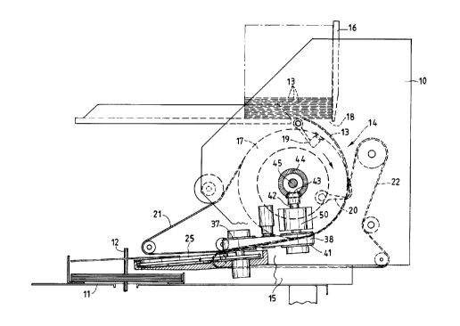
Figures 1 and 2 show part of a packaging apparatus comprising a
conveyor composed of a channel 11 within which a plurality of pushers
slide 12, for example driven by an underlying chain, not
shown. The channel 11 receives a series of sheet inserts 13, for
example from a plurality of lateral drum feeders 14, of which only
one is shown, and this only partially.
Between the pusher conveyor 11, 12 and the drum feeder 14 there is
provided a device for rapidly feeding sheet inserts 13 formed in
accordance with the invention.
A device according to the invention is positioned within the main
frame 15 of the conveyor 11, 12 or packaging apparatus, to the
side of the conveyor channel 11 along which the graphic and/or
editorial products advance. In the illustrated example this rapid
feed device is located below the drum feeder 14. The drum feeder
14 is bounded by two walls 10 and comprises, for stacked inserts
13, a container 16 positioned above one or more drums 17 for
withdrawing the individual inserts 13 and transporting them
towards the conveyor.
At a base aperture 18 in the container 16 there is positioned at
least one withdrawal element in the form of suckers 19 which
engage the lower surface of the insert 13 and, by rotating,
withdraw it from the container and place it against the rotating
outer surface of the one or more drums 17. These carry gripping
elements 20 of gripper type, which receive the insert from the
`~_ 2168515
-- 5 --
suckers 19 and retain it on the drum during rotation.
The insert 13 is then received between pairs of upper guide belts
21 and lower guide belts 22, which are mutually superposed to
contain the inserts 13. The guide belts 21 and 22 rotate together
with the drums 17, and drag the inserts towards a device according
to the invention.
The device for rapidly feeding the inserts 13, located within the
frame 15, comprises a base plate 23 positioned nearly at the base
of the two walls 10 and provided, in the illustrated example, with
two seats 24 for accommodating a pair of discs 25. The two discs
25 rotate and are provided with a sucker 26 housed in the upwardly
facing surface of the disc and connectable to a vacuum source. In
the seat 24 in the base plate 23 there is located a fixed backing
disc 28, for example of an antifriction and/or self-lubricating
material, which is maintained in contact with the rotary disc 25
by elastic elements 39. In that surface facing the respective
disc 25, the backing disc 28 is provided with a recess 27
extending through a certain arc, for example up to 90~. The
recess 27 is connected at one end to an internal channel 29 which
extends as far as a fixed connector 30 for connection to a tube 31
from the vacuum source.
Each disc 25, rotatably supported on central bearings 40,
comprises, in a region below the surface of the base plate 23,
peripheral toothingjfor its rotation. For this purpose two idle
gearwheels 33 and 34 are located in the base plate 23, the first
gearwheel 33 being interposed between the toothings 32 of the two
discs so as to cause them to rotate in the same direction. The
` 2168515 -
-- 6 --
second idle gearwheel 34 engages the toothing 32 of one of the
discs 25 and is rotated by a further gearwheel 35. The gearwheel
35 is located on a shaft 36 carrying coaxially a toothed pulley 37
rotated by a toothed belt 38 arranged mechanically to rotate in
synchronism with the possible drum feeders 14, guide belts 21 and
22 or similar units which feed the inserts one after another in a
direction perpendicular to the pusher conveyor.
The suckers 26 are snap-fitted into their seats and are free to
rotate so as not to create problems of damage to the insert on
which they engage. To achieve a better grip the suckers 26, of
plastics construction, can for example comprise cross-recessed
suction surfaces.
Consequently the insert 13 which, contained between the two guide
belts 21 and 22, arrives on the base plate 23 is engaged by the
two suckers 26 of the two discs 25 in the position shown by full
lines in Figure 2. As the discs 25 are rotated by the relative
gearwheels as stated, the insert 13, now positioned and locked, is
moved with rototranslational movement into its final position,
shown by dashed and dotted lines in Figure 2. In this manner,
besides being directed into the channel 11, the insert 13 is made
to advance in the same advancement direction as the conveyor
pushers 12.
When the insert 13 reaches its aligned position within the channel
11, the suckers 26 disengage the insert or sheet element 13. In
this respect the suckers 26, rotating with the discs 25, firstly
reach the initial end of the recess 27, ie the initial position
indicated by full lines in Figure 2. They then lie over the
- 2168515
-- 7 --
initial end of the recess 27, to become connected to vacuum and
suck the insert to lock it on the disc. As rotation continues,
after about 90 the suckers 26 reach the final end of the recess
27 and are consequently disconnected from the vacuum source, so
releasing the insert 13.
Alternatively, the suckers 26 could be located fixed relative to
the disc 25. In this case a single disc can be used and the
insert be rotated through 90, such positioning for example being
required relative to the pusher conveyor. With a single disc and
a single sucker it is hence also possible to maintain the arrival
position of the insert 13 for example by providing a cam mechanism
which, on rotating the disc through 90, rotates the sucker in the
same direction to maintain the direction of the insert.
A device according to the present invention hence enables the time
involved in moving the insert to be also used for advancing it in
the direction of advancement of the collection conveyor. Besides
enabling the entire apparatus to operate at an increased rate,
this particular arrangement enables the individual pushers 12 to
be positioned one after another at a smaller distance apart than
in known conveyors used up to the present time.
Figure 5 is an enlarged partly sectional view of the disc drive
region which also advantageously comprises a phasing unit for the
discs. In this manner the positions of the suckers relative to
the inserts being fed can be coordinated to further improve the
feed.
In this respect, the toothed belt 38 is rotated by a toothed
pulley 41 positioned on a shaft 42 contained within a support 50
` 2168515
rigid with a wall lO of the drum feeder or with the frame 15.
Rigid with the shaft 42 there is a bevel gear 43 driven by a
second bevel gear 44 rotating on a shaft 45. An extension or bush
46 fixed to the second bevel gear 44 also supports a further gear
47 engagable with a gear 48 comprising complementary internal
toothing. This latter can be made to securely engage the shaft 45
by a locking pin arrangement indicated schematically by 49. By
disengaging the locking pin 49 from the shaft 45 the internal gear
48 can be withdrawn from the gear 47 to enable it to rotate
freely. This also determines the rotation of the bevel gear pair
44, 43, the shaft 42, the toothed belt 38, the various gearwheels
35, 34, 33 and consequently the discs 25 by means of their
toothings 32. Having achieved the angular phasing of the discs 25
and consequently of the relative suckers 26, to the extent
necessary to delay or to anticipate the sucker suction on the
insert 13, the internal gear 48 is re-engaged with the
complementary externally toothed gear 47. The locking pin 49 is
then re-engaged with the drive shaft 45 to consequently achieve
mechanically synchronized movement of the various elements.
As already stated, the transfer of the insert or a similar sheet
element from the drum feeders or from any other feeder, for
example consisting simply of pairs of superposed belts, hence
occurs without any stressing and moreover with the same direction
of advancement as the collection conveyor. This continuous
transfer motion achieved by the collaboration between the discs
and the suckers means that light, flexible, delicate or other such
products can be fed to the conveyor, which can advantageously have
- 2168515
a smaller pitch between one pusher and the next.
All these arrangements of the present invention result in an
increased production rate with conse~uent lowering of packaging
costs, while always achieving correct packaging.
S It must be emphasized that a device according to the present
invention can be advantageously used for rapidly feeding the said
sheet inserts 13 comprising graphic and/or editorial products,
such as single sheets, signatures, magazines, brochures and the
like, sewn or not sewn, in any prechosen number.