Note: Descriptions are shown in the official language in which they were submitted.
21 68548
PHARYNGEAL AIRWAY
TECHNICAL FIELD
The present invention relates to an airway device for securing a
respiratory air-route necessary for the respiration of an unconscious
patient. More specifically, the present invention relates to a medical
airway implement for securing the respiratory route for a patient, that
is for securing an adequate airway from the mouth through the pharynx to
enable the unconsious patient to inspire or expire air, or oxygen and
anesthetic gases easily so that the patient can be ventilated from the
pharynx to the trachea and then finally to the lungs, and especially for
facilitating intermittent positive pressure artificial ventilation as
needed,without using any tracheal tube during general anesthesia or
while the patient is in a comatose condition.
BACKGROUND ART
Currently available medical implements to secure an airway for
anesthesia, emergency resuscitation or the management of seriously ill
patients include tracheal tubes, oropharyngeal airways, nasopharyngeal
airways, esophageal obstructor airways (EOAs), laryngeal masks (LMs) and
the like.
Tracheal tubes have been most prevalently used because tracheal
tubes surely secure a respiratory route, facilitate the evacuation of
endotracheal secretion, isolate the airway from gastric contents
regurgitated through the esophagus and enables positive pressure
artificial ventilation without any troubles as needed when tracheal
tubes are inserted orally or nasally in patients' tracheae and connected
to anesthetic machines, lung ventilators or resuscitators etc.
~ hen surely inserting a tracheal tube in the patient's trachea for
,
2 ~ ~5~
- 2 -
emergency resuscitation, the intubation of the tracheal tube in a
routine manner requiring direct vision of the larynx with a laryngoscope
is liable to entail serious adverse effects due to neural reflex
actions, such as arrhythmia and the regurgitation of gastric contents.
Thus, the intubation of the tracheal tube is a highly risky, invasive
medical practice which can be safely performed only by a physician
skilled in the endotracheal intubation procedures.
Furthermore, stimulation of the very sensitive pharynx and
oppression of the delicate ciliary epithelium in the trachea with the
tracheal tube and its inflated cuff cause foreign sensation in the
throat, hoarse voice and difficulty in expectoration and, in the worst
case, entails serious complications, such as glottic edema and/or
tracheitis. Accordingly, it is a recent medical trend to avoid, if
possible, inserting any foreign matters in the larynx and the trachea
for the purpose of securing adequate airway. Oropharyngeal and
nasopharyngeal airways have been prevalently used for many years.
However, such an airway is not satisfactorily effective
because such a short airway device is inserted simply in the throat
to hold the root of the tongue mechanically with its tip so as
to prevent airway obstruction by depression. Since the airway
is unable to fully support the total structure of the tongue root,
the use of the airway, in most cases, is not satisfactorily effective.
Furthermore, the airway cannot prevent regurgitation from the
esophagus into the trachea and also requires hermetically holding a
face mask and the patient's jaw by hands during artificial
respiration.
Therefore, the airway can be applied effectively to limited cases
and can be safely used only for a limited time. However, it is a
significant advantage of the airway that the airway, unlike the tracheal
`" ` 21 ~854g
- 3 -
tube, can be used by nurses and ambulance paramedics as well as
physicians skilled in airway manipulation.
Esophageal obstructor airways (EOAs) have been manufactured in U.S.
and have been prevalently used worldwide by ambulance personnel. An
EOA, unlike tracheal tubes, does not require direct laryngoscopy. When
using the EOA, the tube of the EOA is inserted blindly and quickly in
the esophagus, a balloon attached to a part of the tube near the distal
end of the same is inflated in the lower esophagus so that the balloon
comes into close contact with the esophageal wall, thus the lower part
of the esophagus is obstructed with the blind distal end of the tube and
the inflated balloon to prevent the regurgitation of gastrlc contents
and to secure a hermetic condition, and then air is introduced through
the side holes of the tube into the esophagus to force air into the
larynx and the trachea for artificial respiration.
When using an EOA provided with a face mask, the facè mask must be
held in close contact with the patient's face in a hermetic state by
both hands, otherwise, the face mask cannot be held in a hermetic state
on the patient's face. Therefore, it is difficult to perform positive
pressure artificial respiration satisfactorily in a travelling
ambulance. Furthermore, since the EOA must be used in combination with
a face mask, the EOA is unsuitable for use in many surgical operations,
anesthesia and intensive care, and is used mainly by ambulance
personnel for the short-period emergency resuscitation of moribund
patients.
The laryngeal mask (LM) invented by Archibald 1. J. Brain, a
medical doctor of London, U.K. (UK Patent No. 2,111,394) has been
introduced into U.S. and Japan, and has been used in anesthesia and
emergency resuscitation. The LM is formed by attaching a rubber mask
to the open end of a thick, arched tube. When using the LM, the
" 2 1 6~}8/
- 4 -
laryngeal opening (aditus laryngis) is covered with the inflated
silicone rubber mask. The LM has been gradually diffused in the clinical
field since the LM was introduced and its clinical applications have
been published by Brain in a paper on "The Laryngeal Mask" in Br.J.
Aneasth, 1983 by Amaha, et al. "MASUI(Jap. J. of Anesthesia)" and so on
in many medical journals. An improved LM invented by incorporating a
moderate bore tube for removing the liquid collected in the mask region
by suction or siphonage is disclosed in Japanese Patent Laid-open No. 2-
283378 (November, 20, 1990), which, however, has not yet been
commercialized.
The LM has attracted worldwide attention in the clinical field
because the LM does not need the insertion of any foreign matters in the
trachea, can be conveniently used in general anesthesia under
spontaneous respiration only if the LM is set correctly except when the
patient is in a prone position in which the management of respiration
is difficult, and the LM is safe to use and does not entail
postoperative complications. However, it is not necessarily easy to set
the LM at a correct working position in the absence of spontaneous
respiration, and also it is difficult to perform effective positive
pressure artificial ventilation because of gas leakage through the
periphery of the rubber mask when airway pressure exceeds a certain
level (about 30 cmH2O) during intermittent positive pressure artificial
ventilation because the rubber mask cannot be pressed against the
laryngeal opening in the pharyngeal cavity by a pressure high enough to
withstand such a high airway peak pressure, and the regurgitation of the
gastric contents and the flow of the gastric contents into the trachea
~aspiration) cannot be perfectly avoided. Although nurses and first-aid
paramedics, as well as medical doctors, are licensed or allowed to
use the LM in Japan, a sufficient pressure for intermittent positive
`" ` 2168~8
- 5 -
pressure artificial ventilation for emergency resuscitation can be
hardly applied to the patient when the LM is used and it is difficult to
determine a correct depth of the insertion and thus a correct
application position for the LM.
The present invention has been made in view of the foregoing
circumstances and it is therefore an object of the present invention to
provide a pharyngeal airway, without inserting any foreign matters in
the trachea, which can be easily inserted through the mouth to the lower
pharynx to obstruct a transitory part between the lower pharynx and the
esophagus, and it is capable of hermetically sealing the laryngeal
opening to secure an airway for positive pressure intermittent
artificial ventilation.
DI$CLOSURE OF THE INVENTION
A pharyngeal airway in accordance with the present invention
comprises: an arched airway tube having a bevelled opening formed by
diagonally cutting the distal end thereof; and a balloon formed of a
soft, elastic thin film, connected to the circumference of the open end
and a portion near the distal end of the airway tube and capable of
being inflated so as to surround a portion of the airway tube near the
distal end, or in the shape of a double-wall balloon formed of an inner
balloon within the balloon, or two balloons, i.e., a first balloon
capable of being inflated in a ring shape so as to surround a portion
near the distal end of the airway tube and a second balloon capable of
being inflated in a hemispherical shape around a portion of the distal
end of the airway tube defining the bevelled opening. Each of these
balloons is formed so as to maintain a naturally bulged shape of a size
greater than that of the laryngeal opening when the atmospheric
pressure prevails therein. When inserting the airway tube in the mouth,
21 6~54~
.
- 6 -
the balloon is inserted through the lower pharynx toward the esophagus
after shrinking the balloon by evacuating the same with negative
pressure. ~hen the interior of the balloon is opened to the atmosphere
after setting the balloon almost in place, the distal portion of the
balloon inflates naturally. The balloon is fully inflated in the
hemispherical shape after the balloon has been set in contact with the
upper esophageal sphincter to prevent the regurgitation of gastric
contents through the esophagus, so as to be in close contact with the
periphery of the laryngeal opening and with the pharyngeal mucosa in an
airtight state with the bevelled opening of the airway tube held toward
the laryngeal opening.
When the airway tube of the pharyngeal airway of the present
invention is inserted through the mouth into the lower pharynx, the
arched distal end of the tube is made straight and the round distal end
in an anteriorly bevelled shape extends along the backside of pharynx so
as not to enter the laryngeal opening located in front of the distal end
or not to catch uneven portions at the periphery thereof and thereby
being inserted into the esophagus securely. Then a naturally inflated
balloon disposed near the rounded distal end of the airway tube can be
hardly passed through the upper esophageal sphincter so as to limit the
further insertion of the airway tube and a ventilating part formed in
a concave or anterior surface near the distal end of the airway tube
easily coincide with the laryngeal opening. In this state, air is
supplied through a gas supply passage formed in the airway tube to the
balloon connected to a portion of the airway tube around the bevelled
opening and around the edge of the opening to inflate the balloon so
that a transitional region from the lower pharynx to the esophagus and
a region around the laryngeal opening are sealed. Thus, the pharyngeal
airway of the present invention is safe, reliable and easy to use, and
` 21 68~48 - 7 -
can be effectively used as an implement for emergency artificial
ventilation.
Since the balloon of the pharyngeal airway of the present invention
has a distal part capable of maint~ining a naturally bulged shape on
the distal side of the ventilating part, and a proximal part capable of
maint~ining a naturally shrunk shape on the proximal side of the
ventilating part, the airway tube can be easily inserted in the
pharyngeal cavity in co-operation with the shape of the distal end and
can be surely positioned at a correct position since the distal end of
the slightly bulged balloon with the atmospheric pressure catches the
sphincter of the upper esophagus.
Since the airway tube-of the pharyngeal airway of the present
invention is provided with a plurality of elongate ventilating holes
formed and arranged in an even array so that the ventilating holes may
not reduce much the anti-bending strength of the airway tube, the airway
tube can be smoothly inserted in the lower pharynx and has a sufficient
anti-bending strength.
When the airway tube of the pharyngeal airway of the present
invention is internally provided along its longitudinal axis with a
suction tube having a distal end opening in the distal end of the airway
tube and a proximal end connected to a suction connector, gases and
gastric juices regurgitated through the esophagus can be removed by
suction, or drainage whereby the flow of the regurgitated matters into
the respiratory tract can be surely avoided.
BRIEF DESCRIPTION OF THE DRA~INGS
Fig. 1 is a longitudinal sectional view of a pharyngeal airway in
a first embodiment according to the present invention;
Fig. 2 is a longitu~in~l sectional view of a pharyngeal airway in
21 68548
~`
- 8 -
a second embodiment according to the present invention;
Fig. 3 is a longitudinal sectional view of a pharyngeal airway in
a third embodiment according to the present invention;
Fig. 4 is a longitudinal sectional view of assistance in
explAining a mode of using a pharyngeal airway according to a first
embodiment of the present invention;
Fig. 5 is a diagram showing the relation between the internal
pressure of the respiratory tract and the internal pressure of the
balloon during intermittent positive pressure ventilation by using a
pharyngeal airway in accordance with the present invention;
Fig. 6 is a lateral view of a pharyngeal airway in a
fourth embodiment according to the present invention;
Fig. 7 is a lateral view of the pharyngeal airway of Fig. 6 in a
state where the balloon is being slightly inflated;
Fig. 8 is a lateral view of the pharyngeal airway of Fig. 6 in a
state where the balloon has been fully inflated;
Fig. 9 is a lateral view of a pharyngeal airway when the balloon
is inflated in a fifth embodiment according to the present invention;
and
Fig. 10 is an enlarged cross-sectional view taken on the line A-A
in Fig. 9.
BEST MODE FOR CARRYING OUT THE INVENTION
The present invention will be described in detail hereinafter with
reference to the accompanying drawings.
Figs. 1 to 3 show pharyngeal airways in a first, second and
third embodiments, respectively, according to the present invention, and
Fig. 4 shows one of the pharyngeal airways shown in Figs. 1 to 3 in use
of the first embodiment.
" 21 68548
~_ g
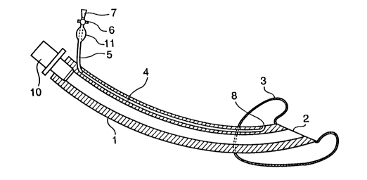
Referring to Fig. 1 showing the pharyngeal airway in the first
embodiment in a longitu~inA~ sectional view, a wide bore airway tube 1
has a distal end diagonally cut to form a bevelled opening 2, and a
proximal end fitted with a connector 10 communicating with the interior
of the airway tube 1. The connector 10 is connected to a resuscitator
or the like. A balloon 3 is capable of being inflated in a
substantially hemispherical shape so as to surround a distal part of the
airway tube 1 and to extend behind the distal end of the airway tube 1,
being connected to the edge of the opening 2 and the outer surface of
the airway tube 1.
A longit~ldin~l small bore gas passage 4 for passing a gas to
inflate or shrink the balloon 3 is formed in the wall of the airway tube
1 so as to open in a pore 8 within the balloon 3. A tube 5 of a small
diameter is connected to the proximal end of the gas passage 4, and a
cock 6 provided with an adaptor 7 and a pilot balloon is fitted in the
free end of the tube 5.
Referring to Fig. 4, when inserting the airway tube 1 of the
pharyngeal airway through the oral cavity O into the lower pharynx P,
the balloon 3 attached to the distal end of the airway tube 1 is
flattened by evacuation and is coated with a lubricant to facilitate
the passage of the airway tube 1 through the oropharyngeal cavity OP
because the oropharyngeal cavity OP is curved approximately at a right
angle, and is pressed and narrowed by the root Z of the tongue.
After the distal end of the airway tube 1 has reached the lower
pharynx P, the cock 6 fitted in the tube 5 is opened. Consequently,
the atmospheric pressure prevails in the balloon 3 and the balloon
3 is allowed to inflate naturally, so that a part of the balloon
3 around the opening 2 of the airway tube 1 bulges slightly. Therefore,
the airway tube 1 can be easily and surely advanced through the lower
~_ ~ 21 68548
- 10-
pharynx P behind the laryngeal opening AL(Aditus laryngis) as far as the
distal end of the airway tube 1 comes into contact with esophageal
sphincter ~ in the upper part of the esophagus E. Then, a gas is
supplied through the tube 5 and the gas passage 4 into the balloon 3 to
inflate the balloon 3 at a moderate pressure so that a region from the
esophagus E to the lower pharynx P is sealed by the balloon 3. Since
the balloon 3 is flexible and is capable of inflating in all directions,
i.e., longitudinally, transversely and backwardly, without covering the
opening 2 of the airway tube 1, the entire surface of the lower pharynx
P through the oropharyngeal cavity OP is sealed gently, and the wide
opening 2 is pressed against the laryngeal opening AL to secure an
airway from the oral cavity 0 through the lower pharynx P to the larynx
L.
When the connector 10 meeting the international standards for
COM ecting to positive pressure artificial respiration devices is
coMected to a resuscitator, and a gas, i.e., air or oxygen, is forced
intermittently into the airway tube 1, the gas flows through the airway
tube 1 and is forced to flow through the bevelled opening 2 and the
larynx L into the trachea T for inspiration. ~hen the pressure is
removed, a gas flows in the reverse direction for expiration into the
atmosphere.
The balloon 3 is formed of a soft, stretchable thin film so that
the balloon 3 conforms closely to the undulated mucosa forming the
surface of the lower pharynx for airtight sealing under the atmospheric
pressure when the pressure of the gas in the balloon 3 is about 30 cm
H20 or below and is capable of achieving perfect sealing without
injuring the mucosa in contact therewith. When conducting intermittent
positive pressure artificial ventilation by intermittently applying a
gas pressure above that pressure through the airway tube 1, the gas
21 68548
pressure, i.e., a positive pressure in the respiratory tract, acts
through the opening 2 of the airway tube in contact with the periphery
of the laryngeal opening AL on the outer surface of the balloon 3, so
that the flexible balloon 3 is locally deformed and compressed and the
internal pressure of the balloon 3 is raised intermittently to a
pressure equal to the pressure prevailing in the respiratory route as
shown in Fig. 5, whereby the airtightness can be naturally secured.
Fig. 2 shows a pharyngeal airway in a second embodiment according
to the present invention intended to change the internal pressure of a
balloon 3 intermittently by ch~nging the internal pressure of the
balloon 13. The pharyngeal airway shown in Fig. 2 is basically the same
in construction as the pharyngeal airway shown in Fig. 1, except that
the former is provided within the balloon 3 with an inner balloon 13
formed of a stretchable thin film, and one or a plurality of side holes
9 formed in a portion of an airway tube 1 enclosed in the inner balloon
13 to interconnect the interior of the inner balloon 13 and that of the
airway tube l.
When a connector 10 attached to the proximal end of the airway
tube 1 is connected to a resuscitator and a gas, i.e., air or oxygen, is
supplied intermittently into the airway tube 1 for positive pressure
artificial ventilation, the gas flows through the holes 9 into the
inner balloon 13, and the pressure of the gas acts directly on the inner
surface of the inner balloon 13 to inflate the inner balloon 13.
Consequently, the internal pressure of the balloon 3 increases
accordingly and the balloon 3 ex~nds uniformly in all directions
without being locally deformed. Therefore, the balloon 3 does not move
relative to the mucosa in contact with the balloon 3 and injures the
mucosa scarcely, whereby the pharyngeal airway can be securely held in
the lower pharynx.
" ` ` 21 68548
- 12 -
Referring to Fig. 3 showing a pharyngeal airway in a third
embodiment according to the present invention, a wide bore, arched
airway tube 21 has, similarly to the airway tube 1 shown in Fig. 1, a
bevelled distal end diagonally cut to form a bevelled opening 28, and a
proximal end fitted with a connector 30 communicating with the interior
of the airway tube 1. The connector 30 is connected to a resuscitator
or the like. A first balloon 22 capable of being inflated in a ring
shape so as to surround the bevelled opening 28 and a part of the
airway tube 21 extending behind the bevelled opening 28 is connected to
the distal end of the airway tube 21, and a second balloon 23 capable of
being inflated in a hemispherical shape is attached to the surface
of the airway tube 21 opposite the bevelled opening 28.
Small bore longitudinal gas passages 24 and 25 for passing a gas
to inflate or shrink the balloons 22 and 23 are formed in the wall of
the airway tube 21 so as to open into the balloons 22 and 23,
respectively. Tubes 26 and 27 of a small diameter are connected to the
proximal ends of the gas passages 24 and 25, respectively, and cocks
each provided with an adaptor and a pilot balloon are fitted in the
free end of the tubes 26 and 27, respectively. As shown in Fig. 3, a
suction passage 31 for sucking out gastric and esophageal discharges
may be formed from position near the proximal end of the airway tube 21
fitted with the connector 30 through the wall of the airway tube 21 so
as to open in a suction opening 32 at the distal end of the airway tube
21. Preferably, the suction passage 31 has a diameter in the range of
about 3 to about 5 mm and a circular or an elliptic cross section.
The pharyngeal airway shown in Fig. 3 is provided with two balloons
22 and 23 capable of being individually inflated and shrunk, instead
of the single balloon 3 of the pharyngeal airway shown in Fig. 1.
Referring to Fig. 4, when the airway tube 21 is inserted through the
` ` 21 68548
- 13 -
oral cavity O in the lower pharynx P, the first balloon 22 is capable
of being inflated in a ring shape so as to surround the laryngeal
opening AL hermetically, and the second balloon 23 is capable of being
inflated in a hemispherical shape at a position on the airway tube 21
opposite the bevelled opening 28 toward the rear side of the lower
pharynx P. When using the pharyngeal airway, the airway tube 21 is
inserted in the pharynx with both the balloons 22 and 23 evacuated to
shrink the balloons 22 and 23 to the least possible size, the insertion
of the airway tube 21 is stopped when the distal end of the airway tube
21 reaches the lower pharynx P and the naturally inflated balloons 22
and 23 come into light contact with the esophageal sphincter M in the
upper part of the esophagus E narrowing from the lower portion of the
larynx. After confirming that air is flowing through the respiratory
tract, the first balloon 22 is inflated and positive pressure artificial
respiration is started. If the gas leaks at a high rate, then a gas is
supplied to the second balloon 23 to press the first balloon 22 against
laryngeal opening AL at the proximal level of the esophagus to enhance
the airtightness between the laryngeal opening AL and the first balloon
22 so that the sealing effort of the first balloon 22 is able to
withstand the maximum inspiratory pressure for pressure respiration.
Even if the gas staying in the stomach and the gastric juice
regurgitate, the leakage of the gas and the gastric iuice into the
respiratory tract can be prevented. The gas and the gastric juice can
automatically escape to the atomospher or be positively removed by
suction through the suction passage 31.
There is no particular restriction on the materials forming the
airway tubes and the balloons of the pharyngeal airways in accordance
with the present invention, and the airway tubes and the balloons may
be formed of any suitable materials generally used for manufacturing
` ~ 2~68548
- 14 -
medical implements, provided that those materials are highly safe, soft
and flexible; soft vinyl resins and silicon rubbers are suitable
materials. The balloon 3 of the first embodiment shown in Fig. 1
having a part naturally maintaining a bulged shape and other part
maint~ining shrunk shape under the atmospheric pressure, and the
balloons 22 and 23 of the third embodiment shown in Fig. 3 naturally
maint~ining bulged shapes or shrunk shapes, respectively, can be easily
formed by selectively determining the thickness and the hardness of the
material forming the balloons 3, 22 and 23.
Fig.6 is a lateral view of a pharyngeal airway in a fourth
embodiment according to the present invention, Fig. 7 is a lateral view
of the pharyngeal airway of Fig. 6 in a state where the balloon is being
slightly inflated, and Fig. 8 is a lateral view of the pharyngeal airway
of Fig. 6 in a state where the balloon has been fully inflated.
Referring to Figs. 6 to 8, a wide bore arched airway tube 41 has a
closed, round distal end in a bevelled shape extending toward the
proximal end and is provided with a ventilating part 42 near the distal
end on the concave or anterior surface thereof. A plurality of
longitudinally elongate ventilating pores 42a (for example, nine
ventilating pores) are formed in the ventilating part 42 in an even
arrangement so as not to reduce the anti-bending strength of the airway
tube 41. A balloon 43 is attached to the airway tube 41 at a portion
around the ventilating part 42 so as to enclose the distal part of the
airway tube 41 and surround the ventilating part 42 when inflated to
seal hermetically a transitional part from the lower pharynx to the
esophagus, and the laryngeal opening AL.
A small bore gas supply passage 44 is formed longitudinally in the
wall of the airway tube 41 so as to open in a pore 48 opening into the
interior of the balloon 43. A tube 45 fitted at its proximal end with
21 68548
~- - 15 -
a cock 46 with a pilot balloon 49 connected to an adaptor 47 is
connected to the proximal end of the gas supply passage 44. The adaptor
47 is connected to an implement for supplying a gas into and removing a
gas from the balloon 43 to inflate and shrink the balloon 43, such as an
injection syringe.
There is no particular restriction on the materials forming the
airway tube 41 and the balloon 43 of the pharyngeal airway, and the
airway tube 41 and the balloon 43 may be formed of any suitable
materials generally used for manufacturing medical implements, provided
that those materials are highly safe, soft and flexible; soft vinyl
resins and silicone rubbers are suitable materials. The balloon 43
having a part capable of naturally maint~ining a bulged shape and the
rest part capable of naturally maintAining a shrunk shape can be easily
formed by selectively determining the thickness and the hardness of the
material forming the balloon 43.
The operation of the pharyngeal airway in the fourth embodiment
will be described hereinafter. Referring to Fig. 7, when inserting the
airway tube 41 of the pharyngeal airway through the oral cavity O in
the lower pharynx P, the balloon 43 is evacuated and held in a flat
shape with negative pressure as shown in Fig. 6 and is coated with a
lubricant, because the oropharyngeal cavity OP is curved and is pressed
narrow by the root Z of the tongue when the distal end of the airway
tube 41 passes the oropharyngeal cavity OP. After the round distal end
of the airway tube 41 along the backside has passed the oropharyngeal
cavity OP and has reached the lower pharynx P without catching the
laryngeal opening AL, the cock 46 fitted in the proximal end of the tube
45 is opened to apply the atmospheric pressure to the interior of the
balloon 43. Then, the distal part 43a of the balloon 43 on the distal
side of the ventilating part 42 inflates naturally in a shape as shown
" ~_ 2168548
- 16 -
in Fig. 7, and the airway tube 41 can be easily advanced as far as the
balloon 43 is obstructed by the lower pharynx P behind the laryngeal
opening AL and the esophageal sphincter M narrowing the transitional
portion to the upper part of the esophagus E.
In this state, where the balloon 43 is obstructed by the esophageal
sphincter M, a gas is supplied through the tube 45 and the gas supply
passage 44 into the balloon 43. Then, the soft and flexible balloon 43
is inflated in all directions, i.e., longitudinally, transeversely
and backwardly the distal part 43a of the balloon 43 comes into light
sealing contact with the entire surface of the lower pharynx P, the
proximal part 43b of the balloon 43 comes into light sealing contact
with the periphery of the laryngeal opening AL and the inner surface of
the lower pharynx, and the ventilating part 42 are disposed opposite to
the laryngeal opening AL to secure an airway communicating with the
larynx L.
When a connector 50 meeting the international standards for
positive pressure artificial respiration is connected to a resuscitator,
not shown, and a gas, i.e., air or oxygen, is forced intermittently into
the airway tube 1, the gas flows through the airway tube 41 and is
forced to flow through the ventilating part 42 of the airway tube 41 and
the larynx L into the trachea T for inspiration. When the pressure is
removed, a gas flows in the reverse direction for expiration.
The balloon 43 is formed of a soft, stretchable thin film so that
the balloon 43 conforms closely to the undulated mucosa forming the
surface of the lower pharynx for airtight sealing under the atmospheric
pressure when the pressure of the gas in the balloon 43 is about 30 cm
H20 or below and is capable of achieving perfect sealing without
injuring the mucosa in contact therewith. When conducting intermittent
positive pressure artificial ventilation by intermittently applying a
21 6854~
- 17 -
gas pressure above that pressure through the airway tube 41, the gas
pressure, i.e., a positive pressure in the respiratory tract, acts
through the ventilating part 42 disposed opposite to the laryngeal
opening AL on the outer surface of the balloon 43 sealing the
periphery thereof, so that the flexible balloon 43 is locally deformed
and compressed and the internal pressure of the balloon 43 is raised
intermittently to a pressure equal to the internal pressure of the
airway as shown in Fig. 5, whereby the airtightness can be naturally
secured.
Fig. 9 is a side view of a pharyngeal airway in a fifth embodiment
according to the present invention, and Fig. 10 is an enlarged cross-
sectional view taken on the line A-A in Fig. 9. An arched airway tube
51 has, similarly to the arched airway tube 41 of the fourth embodiment
shown in Fig. 6, a closed, round distal end and a ventilating part 52 in
a recessed surface near the distal end. The airway tube 51 is provided
with the ventilating part 52 of a plurality of ventilating holes 52a on
the recessed surface.
A balloon 53 is attached to the airway tube 51 so as to enclose
the distal part of the airway tube 51 and surround the ventilating part
52 when inflated. Figs. 9 and 10 show such states in which the balloon
23 is inflated.
A small bore gas supply passage 54 is formed longitudinally in the
wall of the airway tube 51 so as to open in a pore 58 opening into the
interior of the balloon 53. A tube 55 fitted at its proximal end with
a cock 56 provided with a pilot balloon 59 connected to an adaptor 57 is
connected to the proximal end of the gas supply passage 54. A suction
passage 61 for sucking out gastric and esophageal discharges is formed
from a position near the proximal end of the airway tube 51 fitted with
a connector 60 through the wall of the airway tube 51 so as to open in
` 2168548
,
- 18 -
a suction opening 62 at the distal end of the airway tube 51.
Preferably,the suction passage 31 has a diameter in the range of
about 3 to about 5mm and a circular or an elliptic cross section. When
using the pharyngeal airway of Fig. 9, the airway tube 51 is inserted in
the pharynx with the balloon 53 evacuated to shrink the balloon 53, the
insertion of the airway tube 51 is stopped when the distal end of the
airway tube 51 reaches the lower pharynx P and the distal end is
obstructed by the esophageal sphincter M in the upper part of the
esophagus E. After confirming that air is flowing through the
respiratory tract, the balloon 53 is inflated and pressure artificial
respiration is started. Then, there is formed a support of the proximal
part of the balloon 53 to press the airway opening 52 against the
periphery of the laryngeal opening AL to hold the airway tube 51 in
place, and the distal part of the balloon 53 is pressed against the
lower pharynx P and the inner surface of the esophagus E to enhance the
sealing effort between the balloon 53 and the laryngeal opening AL so
that the sealing effort of the balloon 53 is able to withstand the
maximum inhalation pressure for possitive pressure respiration.
Even if the gas staying in the stomach and the gastric juice
regurgitate, the leakage of the gas and the gastric juice into the
respiratory tract can be prevented by positively removing the gas and
the gastric juice by suction through the suction passage 61.
CAPABILITY OF EXPLOITATION IN INDUSTRY
The pharyngeal airway of the present invention, not to be inserted
in the trachea, can be easily inserted through the oral cavity in the
lower pharynx, obstructs a transitional region from the lower pharynx
to the esophagus, and seals the periphery of the laryngeal opening in an
airtight state to secure an airway for positive pressure artificial
` 21 68548
- 19-
ventilation. The pharyngeal airway of the present invention is safe,
reliable, easy to use and very effective for use as an implement for
emergency artificial ventilation.