Note: Descriptions are shown in the official language in which they were submitted.
.1 . ................................................ .
2 1 68603 O9HL18722
BACKGROUND OF THE INVENTION
Numerous arrangements have been proposed for
mounting electric components, such as switches, in
S various pieces of equipment. U.S. Patent Number
5,256,841, assigned to General Electric Company the
assignee of the present invention, shows and
describes an arrangement for mounting components
like switches in equipment such as large electric
appliances.
Some electric controls are fairly bulky and
exert significant forces on their mountings. For
example electric controls, like motor driven
timers, are used in appliances such as clothes
washers and dryers for example. They are
relatively large and heavy and timers and other
controls which incorporate motors exert torque on
their mounting arrangements. Prior arrangements
for quickly mounting such electric controls have
not been totally satisfactory.
One object of the present invention is to
provide an improved mounting for electric controls.
SUMMARY OF THE INVENTION
In accordance with one form of the present
invention an electric control mounting comprises an
electric control housing with a front, a lateral
periphery and a control shaft extending forward of
the front. A planar base covers the front and
includes an opening through which the shaft
extends. A pair of mounting ears extend from the
base outward of the housing periphery on
2 1 6 8 6 0 3 09HL18722
substantially opposite sides of the shaft and lie
in a plane parallel to the base. a resilient
finger is positioned outward of the housing
periphery and a tang formed at the end of the
finger extends forward of the base. A mounting
plate has an opening formed to receive the control
shaft, a pair of mounts on substantially opposite
sides of the shaft receiving opening and adapted to
mate with corresponding ones of the ears, and an
additional opening adapted to receive the tang as
the ears become fully mated with the mounts.
BRIEF DESCRIPTION OF THE DRAWINGS
Fig. l is a simplified perspective view of a
clothes dryer incorporating a control mounting
embodying the present invention.
Fig. 2 is a fragmentary rear perspective view
of the control panel assembly of Fig. l, with the
timer removed for purposes of illustration.
Fig. 3 is a view similar to Fig. 2, but
showing the timer in its mounted position.
Fig. 4 is a simplified cross section view
generally as seen along line 4-4 in Fig. l.
Fig. 5 is a cross section view generally as
seen along line 5-5 in Fig. 4.
DETAILED DESCRIPTION OF PREFERRED EMBODIMENT
Referring now to Fig. l, there is shown a
clothes dryer 10 incorporating one form the present
invention. The dryer l0 includes a cabinet 11 and
a control housing 12, generally referred to as a
_ 2 1 68603 09HL18722
backsplash. A door 13 provides access to the
interior of the dryer for loading and unloading
fabrics to be dried.
Part of the control housing is a control panel
assembly 14, which includes various electric
controls for setting and regulating the operation
of the dryer. It will be understood that the
expression "electric control" is used in a broad
sense and includes such items as motor driven
timers and end of cycle buzzers or other signal
devices, as well as switches that control operation
of the dryer motor and heating unit. Other
appliances incorporate other electric controls and
it will be understood that a clothes dryer, a timer
and a buzzer are used herein merely as examples of
appliances and electric controls.
Referring particularly to Fig.'s 2 and 3, the
panel assembly 14 includes a control mounting plate
15 and a cover member 16. The plate is generally
planar, is formed of relatively heavy metal, such
as sheet steel, and serves as a mounting for
various electric controls, such as timer 17. A
plurality of tabs 19 project from the lower edge of
plate 15 and each tab includes a slot 20.
The cover member 16 conveniently may be formed
of a thin sheet of decorative metal and
conveniently includes graphic elements as an aid to
the user in operating the various controls. The
member 16 is generally planar and includes a
peripheral rim 22. A plurality of tabs 23 project
form the lower edge of rim 22 and correspond to the
slots 20. The plate 15 is placed within the rim 22
with the tabs 23 in the slots 20 and the tabs 23
I 2 1 6 8 6 0 3 09HL18722
are bent over to secure the plate and cover
together. Additional details of the assembly of the
plate 15 and cover 16, as well as the mounting of
that assembly on the appliance may be had by
reference to co-pending application (9D-HL-18723),
by Jon Katz et al, entitled Improved Appliance
Backsplash Assembly, and assigned to General
Electric Company and incorporated herein by
reference.
Each of the electric controls, such as the
timer 17 for example, conveniently is mounted to
the mounting plate 15. Referring particularly to
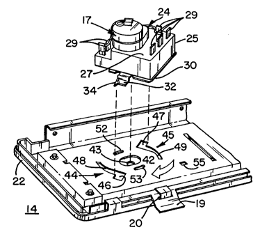
Fig.'s 2,3,4 and 5, the timer 17 includes a housing
24 with a peripheral wall 25 and having a front 26
and a back 27. It will be understood that electric
controls are not necessarily rectangular and the
peripheral wall 25 may have a number of different
cross section shapes. A control shaft 28 projects
forward from the front 25 of the control housing 24
for the operator to set the timer. Electric power
is provided to the timer through terminals 29
projecting through the back 27 of the housing 24.
It will be understood that the particular timing
mechanism contained in the housing 24 is not part
of the present invention and has not been disclosed
for the sake of simplicity.
The housing includes a planar base 30 which
covers the front 25 of the housing and includes an
opening 31 through which the shaft extends. A pair
of mounting ears 32,33 project from the base
outward of the peripheral wall 25 on substantially
opposite sides of the shaft 28 and opening 30.
Each ear 32,33 is generally planar in form but may
09HL18722
- 2 1 68603
include a bent over corner 34,35 respectively.
Each ear is offset forward of the base 30 and the
ears lie in a common plane parallel to the plane of
the base 30. A resilient finger 36 extends from
the base 30 outward of the peripheral wall 25 and
lies in the plane of the base. A tang 37 projects
from the distal end the finger 36 to a point
forward of the base 30. A pair of pins 38,39
project forward of the base 30 on substantially
opposite sides of the shaft 28. The pins are
spaced outward from the shaft only a small distance
and, in any event, less than the distance to the
peripheral wall 25.
The mounting plate 15 is configured to
cooperate with the housing 24 for quickly mounting
the housing on the plate while, at the same time,
providing a stable mount for a relatively large and
heavy control such as a timer. To this end the
plate 15 is provided with an opening 42 through
which the shaft 28 passes when the housing is
mounted on the plate. A complimentary opening 43
is formed in the cover member 16, through which the
shaft also passes. A pair of mounts in the form of
arcuate key hole openings 44,45 are formed on
substantially opposite sides of the opening 42.
The openings 44,45 are adapted to mate with the
ears 32,33 respectively. To that end the openings
44,45 include large first portions 46,47 that are
sized and positioned to enable the ears 32,33 to
pass through the plate 15. The openings 44,45 also
include arcuate slot portions 48,49 respectively
which receive the offsets in the ears 32,33 so
that, when the housing 25 and base 28 are rotated
2 1 6~603 09HL18722
about the axis of shaft 28, the ears 32,33 will be
brought into overlapping relationship with the
plate 15 adjacent the slot portions 48,49.
A second pair of arcuate openings 52,53 are
formed in the plate on substantially opposite sides
of opening 42 and are adapted to receive pins 38,39
respectively. The openings 52,53 are sufficiently
long to accommodate rotation of the housing 25 and
base 30 to move the ears 32,33 well into the slot
portions 48,49. On the other hand the slots 52,53
are just sufficiently wide to closely accommodate
the pins 38,39. In this manner the slot and pin
pairs add to the stability of the mounted control.
An additional opening 55 is formed in plate 15 and
is adapted to receive tang 37 as the ears 32,33
become fully mated in the slot portions 48,49. This
engagement of the tang 37 in the opening 55
prevents subsequent movement of the timer 17 until
some tool, such as a screw driver, is used to
remove the tang from the opening 55.
The timer 17 is mounted on the plate 15 by
inserting the shaft 28 through the openings 42,43
until the ears 32,33 pass through the large
portions 46,47 of key hole openings 44,45 and the
pins 38,39 are received in openings 52,53. The
housing 17 and base 30 are then rotated until the
tang 37 is received in opening 55. In that
position the ears completely overlap the portions
of plate 15 adjacent the slot portions 48,49 and
preferably the pins 38,39 are at the ends of slots
52,53. It will be noted that the rotation of the
ears 32,33 is such that the leading part of the
ears are the bent over 34,35. This assures that
09HL18722
- 2 1 68 603
the ears and plate 15 will not snag. The wide
spacing between the engagement of ear 32 in slot 48
and the engagement of ear 33 in slot 49 provide
significant strength and stability to the mounting,
which is enhanced by the engagement of pins 38,39
in slots 52,53.
While a specific embodiment of the invention
has been illustrated and described herein, it is
realized that modifications and changes will occur
to those skilled in the art to which the invention
pertains. It is therefore to be understood that
the appended claims are intended to cover all such
modifications and changes as fall within the true
spirit and scope of the invention.